Transcription
OLYMPUS STEREO MICROSCOPESMODELSVMF, VMT & VMZREPAIR MANUALOLYMPUS
TO OLYMPUS MICROSCOPE SERVICING PERSONNELBefore repair of microscopes of VM series:Although this repair manual refers only to the methods of repair and adjustment of VMT-4, VMT-2 andVMZ of the VM series, it also enables you to understand those of VMF.Listed in this repair manual are a variety of tools and jigs, without which the required optical adjustmentsare not possible. lt is, therefore, requested that the optical system not be disassembled unless the necessaryjigs are available.Requisites for repairs:1. First of all, ascertain what parts of the microscope the user or owner of which wishes you to repair.2. Never fail to check the entire function of the microscope before you commence its repair.a) Find out what parts are defective and how much they are damaged.b) Prior to repair, think of the best possible order of disassembling the defective parts in a mostefficient way.·3. After completing the repair, check the functions of not only the re-assembled parts but also the entiremicroscope to make sure no defect should be left unremedied.4. Be careful not to deform repair parts during the assembly; make it practice to use tools and jigs specified for purpose.5. Make repairs promptly and accurately.
CONTENTS1. REPAIR TOOLS AND GREASES . .2.EXPLODED PARTS DIAGRAMS . 23.DISASSEMBLY OF VMT-4 OR VMT-2 . 64. ASSEMBLY OF BINOCULAR TUBE V-BI 55 . 115. ASSEMBLY OF BODY V-BT . 196. OVERALL ADJUSTMENT . 217.DISASSEMBLY OF VMZ . 288. ASSEMBLY AND ADJUSTMENT OF VMZ . 309.DISASSEMBLY OF STAND V-STA . 3610. ASSEMBLY OF STAND V-STA . 4111. TENS.ION ADJUSTMENT OF FOCUSING KNOBS . 4412. ADJUSTMENT OF PINION AND RACK . 4513. STICKING OF SLIDING SURFACE OF FOCUSING MECHANISM . 4614. PLAY IN SLIDING OF FOCUSING MECHANISM . 4715. OPTICAL ALIGNMENT FOR ZOOM LENSES OF VMZ (V-BZ-2) . 48
1. REPAIR TOOLS AND GREASES1-1Regular 800210022002300270035020502161021102710281131Set of screwdrivers (6 pes.)Phillips screwdriver (medium size)Phillips screwdriver (large size)Screwdriver (large size)Adjustable spanner (round tip)Adjustable spanner (flat tip)Handle of small size Phillips screwdrivers, using OT 0027Tip of small size Phillips screwdriver, using OT 0023Tweezer (special· made)Alien wrench (2 mm) (In case of VMZ 3 pes. are needed.)Set of Alien wrenches (8 pes.)Hi-Super Bond (adhesive).Alon-Aipha (adhesive)Araldite (adhesive)Shellac (20 g)1-2 Special Tools and Jigs*C-2C-15KKAA 0008KN 0003KN 10G 1OX Eyepiece with cross-hairFocusing magnifier (PM-FT)Pin face wrench tor coarse adjustment nut (AA 000800, AA000900)Test plate for Stereo Microscope Alignment (5/100 concentric)Standard eyepiece for optical tube length alignmentJig for interpupillary distanceSupport standJig for observation tube alignmentStandard objective lens for optical tube lengthPositioning jig for objective lens tubeJig ·for zoom lens alignment1-3 Greases5 g} Same kind of grease5 g} Same kind of grease5 g} Same kind of greaseOTOTOTOTOTOT200720082011201220232024*In case of repairing a small number of the microscopes, expensive KN0027 can be substituted byregular GWlOX or GWH10X eyepiece which is attached to the microscope. Although accuracysomewhat deteriorates as a result, it is not to such an extent as to adversely affect observationthrough·the microscope.-1-
2. EXPLODED PARTS DIAGRAMSVM SERIESVMF-1 (lX)VMF-2(2X)VMF-4(4X)VMT-2( 1X·2X)VMT-4(1X·4X)V-8155FigU8V-BFFigUV-lX Fig.%V-2X Fig.%V-4X Fig.%V-AN Fig V-AL0.75XV-AL0.5XV-AL 1.5XV-AL2XV-STI Fig%Fig.%Fig.%Fig.%Fig%V-ET Fig YsV-ILAM Fig%V-STA Fig%V-IHAFig]iB-LHMV-PO Fig.%c1llmrofCLGV-ILAB Fig FigMV-LS 15 r -. V-IHBFig]iTL Fig%-2-
3. DISASS EMBLY OF VMT·4 OR VMT-2In this repair mar'luol. the left or tight sido o f themi croscop e is, as showr'l in Fig. 1. the side o n the leftor right as viewed from the J)osi tion ot the operatoror the observer. unless otherwise specified.A lso, ul'lless o therwise specifie d, tho screws and nutsarc threaded right·handcdly. To loose'' thom fo rd isassembly, therefore, turn them countcrclockwisearwJ to tighten for assembty, tu m them clockwise.Fig. 13- 1 Loosen Scr ew AA92 1800 and pull up llo iyVMT-4 for romovo l l rom Stand V·STA .lSoc Figs. I and 2.)Fig. 23·2Re novc Obj c tivoCover AA9l 6200 by wl·scrcwi l9 3 pieces of CUK 3x 10SA alter turningthe Body upside down.ISee Fig. 3.)Fio. 3- 6-
3·3RemovE) M ag., i tication Changer AA91 750 0 (orA A9 17400 in case of VMT·2).·· .:ll(See F i . 4.) [AA9 17500(AA9 174001Fi1), 43·4Remove Tufret V ·BT by unscrewing 3 piocos o fCUK3x8SA.(Sco Figs. 4 and 5.)3·5 Remove Click Spring AA917900 by unscrewing(See Fig. 5.)2 pieces o f 3PUK2x4SA.Fig. 53·6 Remove Objeclive Mount Assem bly AA9'16300by unscmvo if\9 2 piccos of AB3x 12SA from eachcomponent3 ·7 Remove Shaft AA917700.3·8 Remove Screw AA9 17800.Fig. 6- 7-(S oFig. 6.)(See Fig. 6.)(Soo Fig. 6.)
3·9 Unscrew the left and right eyepiece 1eeveosscml l ios.(Sec Fig. 7.)ea.Fiy, 7J . 10 Reonovo Mirror Covers AA930800 and AA·930900 by UJ'I CrCwing 2 pieces each o f CUK3x6SA.(See Fig. 8.)Mirror COVC AA930900 is on the loll andMirror Cover AA930800. on the right.Fit. 83· 11Remove Base of Mirror Assembly AA281400in caso of VMT·4, or AA9 17 100 111 case ofVMT·2, by unSCU.l'wing Nt.1lS AA071300 withAdjustohlo Spanner OT0021 .(Sec Fig. 9.)The jollowillg components arc for VMT ·4ZJ850900:Base o f Mirror As.sembly AA281400Conoocting Ptate, r tAA930600Conncctio.g Ptate, leftAA930700The touow;ng components are for VMT 2ZJ85 1100:AA917100Bosc of Mirror AssemblyAA930GOOConr.actino Plate, rightAA930700Cou 'ICCtirlOPlate, leftFlo. 9- 8-
3· 12 Aernovc Connecting Plates AA930600 ill'\dAA930700 by unscrewing 3 J)ieces of CUKJx6Sl\ from each plate.Fig. 103· 13 Unscrew the objective assembly fmm ObjectiveMount Assembly AA91 6300.ZJ5l-1900The obj ective assembly is co1nposed o f thefollowing lenses:V- 1XZJ534900V -2X2J535000V - 4XZJ535 100AA916300(Sec F ig. 1 1.)2J5350002J535 100Fig, 1 1- 9 -
AA9360003-14 Disassemble the right eyepiece sleeve.3-14-1 Unscrew 2 pieces of NU3x3SA.a) Separate Outer Tube AA936000 fromInner Tube AA936100.b) Do not try to separate Glass LP032500from Inner Tube AA936100 since they(See Fig. 12.)are glued to each other.NU3x3SA(2 pes.)Fig. 12ACU2x3SA (3 pes.)AA935800ZJ850600LP032500Fig. 133-15 Disassemble the left eyepiece helicoid assembly.(See Fig. 13.)a) Remove Diopter Ring AA935900 by unscrewing 3 pieces of ACU2x3SA.b) Remove Tube AA935800 by unscrewing3 pieces of NU2x2SA.c) Do not try to separate Glass LP032500from Tube AA935800 since they are gluedto each other.d) Brush contaminated grease off HelicoidZJ850600, using xylol or gasoline.After removing the grease, wipe off thexylol or gasoline with dry cloth and applyGrease OT2008.After wiping Glass LP032500 with lenspaper, clean it with the lens paper to whicha solution prepared by mixing 7 parts ofether with 3 parts of alcohol, is applied insmall quantities.The booklet on "How to Clean the Microscope Lens" is available for your lenscleaning.-10-
4. ASSEMBLY OF BINOCULAR TUBE V-BI 554-1AA936000AA936100Temporary assembly of the right eyepiece sleeveFix Outer Tube AA936000 temporarily onInner Tube AA936100 with 2 pieces of NU3x3SA, which must fit into the slot in Inner Tube(See Fig. 14.)AA936100.NU3x3SA(2 pes.)Fig. 14ACU2x3SA (3 pes.)AA935800ZJ850600 NU2x2SA(3 pes.)4-2 Temporary assembly of the left eyepiece helicoida) Fix Tube AA935800 temporarily on HelicalTube ZJ850600 with 3 pieces of NU2x2SAin such a manner that the index line on TubeAA935800 will be located on the left.b) Fix Diopter Ring AA935900 temporarily onHelical Tube ZJ850600 with 3 pieces of(See Fig. 15.)ACU2x3SA.4-3 Fix Connecting Plate AA930600 temporarily onRight Mirror Assembly ZJ535200 with 3 pieces(See Fig. 10.)of CUK3x6SA.4-4 Fix Connecting Plate AA930700 temporarily onLeft Mirror Assembly ZJ536500 with 3 pieces of(See Fig. 10.)CUK3x6SA.Fig. 15- 11 -
4·5 Fix the temporarily assembled right OYCI ieccsleeve tCmllOrarily on Right Mirror Asscmbl\'ZJ535200.ISco Fig. 16.14 ·6 Fix the lomporadly asscmbl(.'d lett oyopicccsleeve tCJYlporari ly on Left Mirror A sson"'blyZJ 536500.(See Fig. 16.)Flu. t64·7 Adjustment o f the eyepiece slcovca Jig and tools rcquirOO,VM·KC005: Jig for ll,.etvation tube align·mentVM·KC006: Standard objective for Of ticaltube lengthG 1OX eyepiece with cross hoirC- 2:Foc sin g magnifier (PM· FT)C- 15:Standard cycpinco tor Ol)tir.nlKN0027:f alignment1 bl Screw S tandard Objective VM·KC006 inlol'the boltom si .le o f Right M irror A sse1'11bly(See Fig. 16.1 and insert Standard ObjectiveVM·KC006 in1o an opening at the ccntcr ofthe top panel o1 Jig VM·KC005 so as toFig. 17mount the Right Mirror Assembly on JtgVM·KCOOS.(See Fig. 17. )Use LSE or al\ electric bulb to illuminoccStandnrd Objective VM·I C006 I rom I hebouom.- 12 -
c)Use of FOCI.lSing (\ lagnifier (PM· FT) C-1 5(1 ) Olympus eyepieces are cormcted for two differe ) t diol)ters, rogclfdlcss o f magnificatiOflS.One type is corrected for - I diopter. the other for - 4 d iop ter. They cM be i fe ,t ified byex ternal appearances as i llustrated below:\\- I d iopter eyepieet.(currentl 1 used)- 4 (tiop ter e') upi ce(old type & KN002'7)These illustr ations above represent the eyepiece GW 10X for stereo m icroscopes.T he - 1 d iomer eyepiece has a plain front surface. while the - 11 diopter eyepiece has a recess0 1\ the front sudace.(2) Focusing with Focusing Magnifier IPM·FT) C- 151} In case of - 1 diopter eyepieces (GW 1OX or GWH 10X):Looking t1u ough the mag.,itier. move the eyepiece portion i n or out I.HHil an object 1,000mm away from the magnifier is brought into focus.-i'f-------------------i[f / -c- ::9 pFnL1.000 mmEvcp i11oe pon io n2) In case or - 4 diopter eyepieces { I N 0027) :Place an object 250 mm away from the C- 15 (PM-FT) and focx s it in the same m anner aswith the - 1 diopter eyepiece.- 13 -
dl ,,.,., KN0027 into Outer Tube AA93GOOOof the right eyepiece sleeve.l' lacc over KN0027 C· l 5 that has been nd·jlrstOO to tocus at a diStallt.'C of 250 I'TIIYI nndfocus the scale oo Standard Objective VM·KCOOG tl\rough C· 15 by moving Ou ter TulleJ\J\936000 up and down after loosoning2 pieces o f NU3x3SA on it.(Sec Fig. 18.1e) Dismount the of the Right Mirror 1\s·scmbly and Standard Objective VM·KCOOGfrorn Jig VM·KC005 and separate them fromeach other.Attach Standard Objective VM·KC006 torig. 10the Left M irror A ssembly in the samemanner as described for the Right M irrorA ss(nnbly in b) above a nd mount thorn onJig VM·KC005. Inser t KN 0027 in to HelicalTube ZJ850600 and focus the scale 011Stondnrd Objective VM·KC006 asil was indl above. by turning the helicoid.f) Aher the focusing. align "0. marking onOiopt.,. Ring AA935900 with the ondcx loneon Tube AA935800 and lix Dioptor· RingAA935900 in p lace with 3 pieces of IICU2x3SII.4·8 Adjustmen t of optical axis with the aid of G tOXeyepiece wl1h cross hair.al Screwing Standard Objective VM KC006into the bouom side of Right Mirror Assem·bly, and inserting Standard Objective VMKC006 lino illl opening ilt the ccmcr oC thetOP l)ltnOI of Jig VM·KC005 so as to mounttho Right Mirror Assembly on Jig VM·KCOOG,pu 1 C·2 G1OX eve piecewi th crosshai r into the righ t eyepiece sleeve. LoosenF .3 pieces o l CUK3x6SA wh ich holcl RightMirror Assembly ZJ535200 in place.(See Fig. 19.110- 14 -
Ad jus1 the POSiuonal relati on between theeon ter o f the crOS hair of C-2 and that ofthe concen tric circles o f Standard O bjectiveVM-K COOO by movi ng Right M irror Asoom ·bly ZJ 53520 0.!Sec Fig. 20.)b) 6 r ing tho r.em er of the cross hair into theshade d squar e at the center of the conc coutccircles that is show n in Fig. 2 1 Olld try 10put both centors as close eo P.ach o ther aspossible.(S.o Fig. 20.1c l Screw 3 piccos of CUK 3x6SA as tightly I)OSsi blc.d ) By the V5C o f Standard ObJective VM KC006and Jig VM·K C005 in the same fnann cr ns in4·7·eL pu1 C·2 G IOX eyepiece w ith crossFig, 20F lg, 21hair into the Loll Eyepiece Sleeve ZJ850600.;.;:. i\'1.; . ;:;.:·· -· ··I'''- 1 :'t:·.W''tll''ld makn the St)llle adjus tmen t os fo r thoAioht 1\tlirro r Assornbly.The dOlled linersindiea te the spou1hat ere ou1 o rfocu 4-9 Check on re 01v ing povA:r with the aid ofGWH I OX or GWI OX eyepieceI f the follow ing phenomena devel op, rcplacoZJ535200 nd the pair o f Mirro r AHem bliesZJ536500 and make the ad;ustmon t all overogaln .(Seo Fig. 22.1a} When conce ntrtc circle s ore focus ed aSongo line. e.g., x-axis, they ore out of focusolong o w thcr lillfJ, e.g., Y·Oxis.b) When the cenacr of conce ntric circles isfocusod, one sec to r of the concc mric c irclosgoos out o f fO .'US.flg. 22- IS-
4· 10Dismount the Mirror Assembly ZJ536!.)()() fromJig VM·KCOOS and "ll arate Standard ObjectiveVM·KCOOO.4-11 Apply Grease OT 2008 to llasc of MirrorAssomiJiy AA28 1400 or AA917100.!Sec Fig. 23.)Fig, 234· 12 Mount Mirror Assembly ZJ850900 or ZJ·85 11 00 on Oaso o f Mirror Assemuly AA281400 or AA917 100 and check if the Inter·P Jpiflary distance adjustment device litsproperty.!Sec Fig. 24.14·13 Remove the left and right eyepiece sleeves.Fit 244-14 Fix Mirror Covers AA930800 and AA930900over the pairor M ir'rorA ssemblies with 11pieces of CUK3x6SA, 2 each on Cove1.!Sec Fig. 25. 1Fig. 2G- t6 -
4· 15 fix Mirror AsS onbly ZJ850900 or ZJ85 1100to Ba o of Mirror Assembly AA28 1400 or(Sec Figs. 25 ond 20.)AA917 100.a) f ix Mirroo· Assembly ZJ050900 or ZJ·851100 in 8Dsc o f M irror Asscrnbly AA·281400 or AA917100. (Apply Grease Or(Sec Fig, 2G.)2008 to the interfaces. )b) AI PIY Grease OT 2008 to the spots indicat·(Sec Fig. 25.)ed by arrows.c) T igh ten Nuts AA071300 with Adjustobln(Seo Fig. 27.)OT 0021.d) In case they Jre loose in the dlfection ofthrusl or the imctpupillarv dislai"W:C adjust·ment dovk:e move w ith too liu tc frict onSt"""""'resistonce. widen the slot in N1.1 t /\A·071300 wi th the tip of a screwdriver, tomake odju stn)(HH.Adjust the slot.Fi9. 27AA011:JOO. ''·-·l. .:. . lFig, 28- 17-
4· 16 Screw Eyepiece Tubes AA936000 ond ZJ850600 into Mirror Assemblies AA535200and AA536500 r.pectively.(See Figs. 28 a d 29.1Fig. 20CAUTION :When assembling the mirror unit. care shouldbo exetctscd 10 keep it free from dust or anyo ther contaminants since the removal is d ffk:ult after the assemblage.- 18 -
5. ASSEMBL V OF BODY V·BTr5· 1 Fix Scmw AA917800 i nto Objective Tur retAA917300, using Hi·Supcr Bond OT 102'1.(Soe Fig. 30.).). F i l . 305·2 Fix Objecti11e T\ rret AA917300 to Stopper BaseAA917200 with Shaft Al\917700. See Figs. 31 ar1d 32.1o Apply Grease OT 2008 to that smface ofStopper Base AA917200 which wi ll be incontact wilh Objccti 1JC Turret AA917300.(Sec Fig. 31.)F ig. 31''Apply G(ease OT 2000 to the o 1) ''in g i ntohich Shah AA9l7700 will be screwed.\"1(See Fig. :!2.)Fig. 32- 19 -
"(' .5·3 Attach Click Spring AA917900 to St OJ por BaseAl\9 17200 with 2 pieces of 3PUK2x4SA.o Pu1 Click Spring AA9 17900 in place so ostosett le l)all B 1/8 securely in lhc V· 5hDJ C groovo In Olllcctive Turret AA917300 ondtighten 2 pieces of 3PUK2x4SA.(See Fig. 33.)Fig, 335·4 Fix lho objective uniu temporarily on ObjectiveTurret 1\1\9 17300.(Sec Figs. 34 and 35.)a) Screw the objectives onto Objective MountAl\916300.Objoctives 1XZJ5349002X ZJ5350004X ZJ535100b) Mount the objective units on Objoclivcl'u1·rot Al\917300. using 2 poirs of A03x 12SI\ oncl KNW 3SA I or each unit.Fig. 34CUK3x8SAFlg. 355-5 Fix 6T unit on Si unit with 3 pieoes of CUK3xSSA.(See Fig. 35.)
G. OVERALL ADJUSTMENT6· 1 A rrange Suppoct Stand VM ·KC004 os seen inF ig. 36.VM·KC003 : Jig lor intcrpupiiiJry disti'JI'\Cevt.1·1(C00 1: Support Sl(ll) dK N0003:Test plate for stereo m icroscopeali!Jfunent (5/ 100 mm concentric}G 1OX eyepiece w ith cmss hnir forC- 2:s tereo microscopesC- 15:KN0027 :Focusing n agf'lifier tpM .FT IStandard eyepiece for optical tubelength alignmen t (See the asterisk·ed n ow orl p age 1.)(Sec F ig. 36.)Fig. 36f ()r J)\lffoc;,lhv ttdiustment, be Sl1re to llPPiv VM·KC003 tO lhC ICh lO(I the d!'J"'It e t CJ iec;c WI)C .VM·KC003Fig, 376 ·2 Adj\.rst the left and the tight 1X objec tivos fNJ arfocali ty.a) Apply shellac to the th readed sec tion o f lheright IX Objective .ZJ534900 and fix it onObjective Moun t AA9 16300.b) 1nsor 1 Ki'J0027 into the right Evel)ieceSleeve AA936000 n d pl ce C- 15 o n theeyepiece. Focus the concentric c ircles onTest Plate KN0003 vJith coatSc adjust nen tk i)ObS.c) Take KN0027 out o f the righ t EyepieceSleeve AA936000 a 'd insert it i ,to the lefteyepiece sleeve. Align "0" on the OiopterRin g with the i 'dcx line.d) Put C- 15 on KN0027 and whi le lookingtiU0\ 9h C- 15, focus lhe concentric c ircleson Test Plate KN0003 by turning the leftObiecti ' e ZJ534900. (The objec tive movesup and down by turningJe) After making sure that they are focused.unscrew the left Objec tive ZJ534900 froonthe objective mount. Apply shellac to thethreaded section o f the left ObjectiveZJS:J4900 aocl put it back on the objectivemount. Repeat step d) above.- 21-
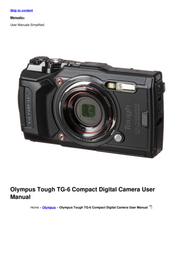
4X OB (ZJ5351 00)AA918000AA918100AA918200AA918300Fig. 38tttt 0.05 0.1 0.02 0.56-3 Parfocalize 4X (2X) objective with 1X objective.a) Turn Objective Turret AA917300 to the 1Xside and focus Test Plate KN0003 throughthe right objective, using C-15.b) Turn Objective Turret AA917300 to the 4Xside and insert one of the 4 washers AA918000 to AA918300 between the rightobjective and the objective mount to makeso much adjustment as to enable the rightobjective to focus Test Plate KN0003 withthe aid of C-15.(See Fig. 38.)c) Adjust the left objective to make it parfocalwith the right objective. [Follow step b)above.]d) Unscrew the objectives from the objectivemount and after applying a small amount ofshellac to each of their threaded sections,restore them to the objective mount.e) Make sure of the parfocality.6-4 Make sure with the aid of C-15 of parfocal itybetween the 1X objective and the 4X (2X) oneand also between the left and the right objectives.* Standard valueLeft and right-1 diopter( 1 graduation)Magnification change -1 diopter( 1 graduation)-22-
6-5KN0003Fig. 39(1) Distanc e of movem ent-- I-to the rightI.-,--. ,Distance ofupward move·mentAdjust ment for centra tion of the left and theright 4X (2X) objectivesa) Loosen 2 Screws AB3x 12SA on the rightObject ive Mount AA916 300 and move theobjecti ve mount . Fix with the screws theobjecti ve mount as near at the center of therange of the movem ent as possible.b) Keep 2 Screws AB3x 12SA half tightened inthe left Object ive Mount AA916 300.c) Insert C-2 into the right Eyepiece SleeveAA936 000 and focus Test Plate KN000 3.Shift the Test Plate so as to make the centerof its conce ntric circles coincide with that of(See Fig. 39.)the cross hair of C-2.d) Shift C-2 to the left Eyepiece Sleeve andsee how far the center of the cross hair isfrom that of the conce ntric circles of the(See Fig. 40.)Test Plate.e) Make the center of the concen tric circles ofthe Test Plate coincid e with that of the crosshair of C-2 by moving the integrated left(See Fig. 40.)objecti ve mount .f) After compl etion of the centra tion, tighteng)Screws AB3x 12SA.Make sure of centra tion of the cross hair andthe conce ntric circles by lookin g throug hC-2 inserted firstly into the right EyepieceSleeve and secondly into the left EyepieceSleeve. When they are found eccentric witheach other, repeat steps c) throug h e) untilthey are concen tric.Fig. 40-23-
Fig. 41Distance ofupward movementLDistance of movemen tto the left6-6 Correction of parfoca lity at the change ofmagnification from 1X to 4X (2X) and viceversa, and centratio n of the left and the right1X objectives.a) Set the magnific ation at 4X and insert C-2into the right Eyepiece Sleeve. Move theTest Plate so as to make the center of itsconcentric circles coincide with that of thecross hair of C-2.(See Fig. 41.)b) Change the magnific ation to 1X and seehow far the centers are apart from eachother.(See Fig. 42.)c) Slightly loosen Screws AB3x 12SA in the 1XObjective Mount and bring the center of theconcentric circles of the Test Plate to that ofthe cross hair of C-2 by moving the objective mount.(See Fig. 42.)d) Tighten Screws AB3x12 SA securely.e) Check to see if they are concentric and, ifnot, repeat steps a), b) and c).f) Insert C-2 into the left Eyepiece Sleeve andmake the left and the right 1X objectivesconcentric with each other by followin gsteps d) through g) in 6-5. above.Fig. 42-24-
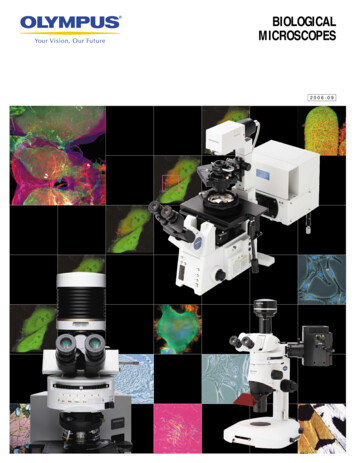
Standards L.I.F.O.1.For centration of tolerance between the left and the right objectives of each magnification L.l. F .0.(Length of I m age Formation Plane of Objective): 0.22.For parcentration tolerance of one objective with the otherL.I.F .0.: 0.2Since the size of the image of an object (specimen) varies with the objective magnification, theterm "Length of Image Formation Plane of Objective" (L.I.F.O.) is used to indicate these standardtolerances in this repair manual.Fig. 43 gives these standards for each magnification. The following formula explains the relationship of the actual length with L.l. F .0.L.I.F.O.Objective powerActual lengthIn case of the 4X objective, for example, the calculation is as follows:Actual length 024 0.05 mmTherefore, the actual length of the 4X objective is within the radius of the smallest of the concentric circles of the Test Plate.The value (standard value) of one graduation for each magnification isschematically shown below:EyepieceAB 0.05 mm (actual length)A'B' 0.2 (L.I.F.O.)0.05 mmC'!0N00.20.2(One graduation for 1X0.2 0.05 mm)0.2(One graduation for 2X 0.1 mm)Fig. 43-25-0.20.2(One graduation for 4X 0.2 mm)
6·7 Perform the f inal checks on the followi ng:a} Padocal ity of the left and the right 1X ob·jectivcs and decenuations ot the left and therigh t 1X objectives.bl Parfocali ty o f the left mt l the r ight 4X {2Xlobj ectives and decentrations of the left andthe right 4X {2Xl objectives.c) Parfocali ty maintained between the 1X al''ldthe 4X objectives after magnification changefro n 1X to -1X and v ice \ erS i Md d ecentra·tions of the same objectives aftor mag11ifica.tion change.d) Ex istence of dust or any other contarnin\HllSOil the lens surfaces (Oust and contamil'lantscan r ad i ly b detected by looki 119 throughthe lenses from the eyepiece side, with alight sourCP. J Iaccd on the ob jective side.el Resolving power (Use GW1 OX or GWH I OXeyepiece for this check.)g) Contrast and d istortiollAny abnormality detected in the final c heckmust be remedied by re1 lacing the relatedparts or by making necessary adjustments.6 ·8 Ois1nount the m icroscope from SuP! Ort StandVM·KC004.6 ·9 Apply shellac to Screws AB3x 12SA to prove 'tObjective MotuH AA9 Hi300 from loosening.{See Fig. 44.1Fig. 44- 2G -
6· 10 P1oce Mognifieotion ChangcrAA9 175 00 orAA9 1740 0 in posi tion.al App ly GreaS l OT 200 8 to whereStopperBaso AA91 ?20 0 .' OmC!i in contactwithMagnificatiOI Cha ngcr AA9 175 00.b) Place Magnific atio " Chnogar AA91750 0in post tion and make sure thot itrotatessmoothl y.(Sec Fig. 45.)VMT-4VMT·21Fig. 456· 11 F lx Objective Cover AA9 16200 in p lace with3 piece. of CUK3x 10SA.Fig, 40AA2 814: VMT·4AA9171: VMT ·26· 12 Check if Magnific atio n Cha ngerAA9 175 00operates prop ctly .a) 11 it does not tu m smoothly, 1oplaco eitherObj ocl ivc Cover AA9 1 620 0 or Magnifica·tion Changer AA9 175 00.b) If it ranles Jongi wdi nally or doesnot H. mlightly. adjust the width of aho slot inBaseof Mirr or Assembl y AA2 814 00 (OI'AA·917 1001.Fig. 47- 27 -(SceFig. 47.1
Flo. 487. DISASSEM BLY OF VMZFig. 49 shows VMZ.Fi9. 407-1 Remove Objective Cover AA916200 oh or urlscrewing 3 pieces o l CUK3x IOSA. (Sec Fig. 50.)Fig. GO- 26 -
1·2 AQmove F ixing Ring AA93 5100 after \lllSCrev.ing 3 pieces of 31'UK2x6S/ \. Also, remcwe anadiustinu wnsher, if any, ne the sorno time.(Sec Fig. 5 1.)Pit), 517·3 Remove P1n AA935300 and detac h CircularCover AA9l17200 aflor unscrewing 2 pieces of3PUK2x3SA.Remove the lct t and the righ t Pins AA93 4900 orAA93SOOO and then Zoom Guide AA935400.!Sec Fig. 52.)Fig. 527·4 Detach the lelt and the light V·BiZ alter un·setcwing 2 piece. ol ACU4xBSA and 1 piece olACU4x6SA borh ol wllich 010 locato i on lhcleft and the right in the top sidu.Detach the left and the right Zoom TubesZJ853400 oftcr unscrewing 3 pieces or ACU4x8SA on the left and the righ L irl the bouo ,Hside.- 29 -(Sec Fig. 53.)
':i ": .7·5 Read page 48, Section 15 prior to dissasemblyof Zoom T ubes 853400.(Sec Fig. 54.1F ig. 548 . ASSEMBLY AND ADJUSTMENT OF VMZFi{1. 558 ·1 Mouflt Base of M irror Assembly ZJ853300 onSupport Stand VM·K C004 and clamp it w ithknob on the side of Suppon Stand VM ·K C004.Insert Zoom Tube AJ853400 (which has beenadjusted independently) into the r ight openi ng(on the side o f Screw AA074200) in Oasc ofM irror Assembly ZJ853300 from above.(See F i9. 55.)Push Zoom Tt.11 e ZJ853400 in the opening withPositioning Jig VM·KC007 md also inson thelatter into tho sa1ne Ol ening w ith its l inearm :Hking being Ofl the r ight.(Sec Fig. 55.)Tigh ten 3 pieces of ACU4x8SA sccuroly, each ofw hich is locatod ot a d iHerem spot on the lowersido of the periphery o f B 1se of t-.11irro r AssemblyZJ853300.(Sec Figs. 53 and 55.)8·2 Insert Zoom Tube ZJ853400 (which has beenadjusted indeperl dontly) into tho lef t openingof Base of Mirror A ssembly ZJ853300 fro rnabove alld fix Zoom Tubo ZJ8 53400 tcmpora·ri ly at any dt.osired position with 3 pieces orACU4x8SA on the lower side o 1 the periphery.(In this case, V M·KC007 is not used .)(See Fig. 56.)Fig. 56- 30 -
8·3 Apply G Oosc OT 2012 to where Pin AA934900or AA935000 comes in con1oct with Sow o fMifl'or 1\stOn"'bly ZJ853300 and incoroonueZoom Cu idc AA935400 itlto Oase of Mirro ·Mscmbly ZJ853300. Screw Pin AA935300 into{Sec Fin. 57.1the Zoon'l Gui fo.- AA93!3 100'- - - - AA035JOOFi{l. G78 ·4 A ttoch F ixir1g Rill9 AA935100 to Zoom GuideAA935 00and apply Grease OT 2012 10 whorethey come in contact with each other. Scf'e\-vtJ em together Ylith 3 pieces of 3PUK2x6SA.(Sec Fig. 58.)Fig, G88·5 Fix MngnrricatiOol Changer AA9 17600 In placeafter iJpplying a thin coat of Cfeasc OT 2008(Sec Fig. 59.)to its inside surface.Fit), SU- 3 1-
8-6 Fix Ob}cccive Cover AA916200 in ! lace w1th3 pieces o l CUK3xlOSA.Fix coch of the left and the right eyCJ iccc tubestcrnpororily in place wi th 2 pieces o f ACU4x8SA oncl I piece of ACU4x6SA, boch o f which( oc Fig. 60.)aro loctnod on tho upper side.Fig. GO8·7Adjustment of optical ax isJigs and tools requiredTest Ploco KN0003G IOX eyepiece with cross l air C-2Alien wrench OT 0205, 3 piecesa)Mount the left and the (jght mirror units OflBase of Mirror Assembly ZJ853300 and fixthcnl together temporarily with 2 pieces 0 rACU x8SA and I piece of ACU x6SA onthe upper sido o f the periphery of the 13oscof Milror Assembly.-n-(Sec Fig.6 1.1
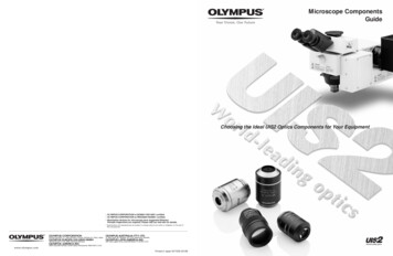
b)The concentriccircles move.Concentric circles of 1 Xmagnificati on being con·centric with those of 4Xmagnifications.(By moving Test Plate KN0003,the center of the concentriccircles positioned with thezoom magnificati on set at 1X· is made to coincide with thatpositioned with the zoommagnificati on set at 4X.)Fig. 62Concentric circles of 1Xmagnificati on being concentric with those of 4Xmagnifications.Insert C-2 into the right mirror unit and setthe zoom magnification at 1X. Move TestPlate KN0003 to make the center of its concentric circles coincide with that of the crosshair of C-2. Change the zoom magnifica tionto 4X and the center of the concentriccircles will move. Then, move the Test Plateagain to the 1X position. Put the zoom magnification back to 1X and the center of theconcentric circles will move again. With theposition of the center of the concentriccircles kept in mind, change the zoommagnifica tion again' to 4X and the centerwill shift once again. Then, move the TestPlate to shift the center of the concentri ccircles to the spot that is memorized aswhere the center was when the zoom magnification was set at 1X. Repeat the abovesteps of moving the Test Plate and changingthe zoom magnifications and the centerpositioned with the zoom magnifica tion setat 1X will finally coincide with that positioned with the zoom magnifica tion being at4X. In this case, the center of the concentriccircles does not have to always coincide withthat of the cross hair.(See Fig. 62.)oStandardL.I.F .0. 0CAUTION :Under no circumstances must the Test Platebe manipulated once the two centers of theconcentri c circles have coincided with eachother.c) Make the center of the cross hair of C-2coincide with that of the concentri c circlesof 1X and 4X magnifications.Apply Alien wrenches OT 0205 to the3 screws, two ACU4x8S A and one ACU4x6SA, both of which are referred to in a)above and make the center of the concentri ccircles of 1X and 4X magnifications coincidewith that of the cross hair by moving thescrews back and forth.(See Fig. 63.)(The center of the concentriccircles of 1X and 4X magnifications is made to coincide withthat of the cross hair by moving the mirror assembly.)Fig. 63o-33-StandardL.I.F .0. 0.2 max.
The two concentriccircles are apart fromeach other.Concentric circles of 1 Xmagnification being concentric with those of 4Xmagnification .(The centers of the concentriccircles of 1 X and 4X magnifications are made to coincide witheach other by moving the ZoomTube.)d) With the left
OLYMPUS STEREO MICROSCOPES MODELS VMF, VMT & VMZ REPAIR MANUAL OLYMPUS . TO OLYMPUS MICROSCOPE SERVICING PERSONNEL Before repair of microscopes VM series: Although this repair manual refers only to the methods of repair and adjustment of VMT-4, VMT-2 and VMZ of the VM series, it also enables you to understand those of VMF. .