Transcription
PDP TV Training Manual2009 Samsung Plasma TVTechnical TrainingThis information is published for experienced repair technicians only and is not intended foruse by the public. It does not contain warnings to advise non-technical individuals of possibledangers in attempting to service a product. Only experienced professional technicians shouldrepair products powered by electricity. Any attempt to service or repair the product orproducts dealt with in this information by anyone else could result in serious injury or death.Information provided in this bulletin is subject to change or update without notice.This training will cover the new 2009 Plasma televisions showing the new features,specifications and changes in design for this model year.1
Recommended Troubleshooting & Repairing Guide:V1.0- Collection of LCDTV Repair TipsLCD/LED & 3D TVRepair Membership SiteProjection TV &DLP/LCD ProjectorRepair Membership SiteV2.0- LCD TV RepairTips & Case HistoriesPlasma & 3D TVRepair MembershipSiteTroubleshooting &Repairing LCD TVGuidePlasma TV Repair GuideDisplay FaultTroubleshooting BasicLCD TV RepairSecrets RevealedLCD Monitor RepairGuideVol .1- 10 Trus RepairCase Histories of LCDMonitorSMPS-Switch ModePower Supply RepairGuideTesting ElectronicComponents like a ProFor BeginnerLaptop MotherboardRepair CourseLaptop RepairVideo Collection
Table of Contents New Features, Specifications and Introduction to 2009 PDP Model ComparisonPower Supply– Power Supply TroubleshootingLogic Board– Logic Board Troubleshooting“Y” Board– “Y” Board Troubleshooting“X” Board– “X” Board TroubleshootingData (Address) Board– Data/Address TroubleshootingVideo Circuit– Video Circuit TroubleshootingAudio Circuit– Audio Circuit TroubleshootingPanel Explanation– Panel Failure ModesAlignment Procedures– Option Bytes22
Introduction to 2009 PDPThis presentation will introduce the 2009Plasma televisions showing the newspecifications, features and the newEnergy Starrated panels.3This presentation will introduce the 2009 Plasma televisions showing the newspecifications, features and the new Energy Star rated panels. Design, PCBchanges and any special servicing requirements.3
Slim & LightSlim Design2009200869%Slimmer1.2”55 Lbs3.8”50" B85086.4 Lbs28%Slimmer2.9”73.6 Lbs50" B55044/42Like the new 2009 LCD models the Plasma models have gotten lighter, thinner andmore energy efficient.4
600Hz Subfield MotionRemoves the blur from fast sceneswith a lot of movement to providea clearer picture.5The 2009 Plasma system has increased the number of steps in sustain from 8 to10. This increases the smoothness of the transitions in picture brightness levelsand offers more color combinations.5
AC Drive System10 Sub FieldsY ElectrodeX ElectrodeAddress (Data) Electrodeeinsidlleve8 sub fieldbright anglebright angleThe sustain period duration determinesthe pixel brightness. A total of 1024levels of pixel brightness are available.Half Brightness is sustain step 9 (Binary5 1 2 ) o n a n d s u s t a i n s t e p 1 0 off.ele le vinsid10 sub field6Other sustain cycles operate using similar methods as the previously describedcycles, alternating the charge polarity at the X and Y electrodes. Each cycle will lasttwice as long as the one before it. A maximum of 10 sustain cycles can beproduced. Maximum luminance will occur when charges are applied to the pixel ateach of the 10 sustain periods.6
10 Subfield Drive Process Changing from 8 subfields to 10 subfields increases thenumber of color choices from 28 (256) to 210 (1024)7Another advantage of the 10 sub field system is smoother video linearity, brighterpicture and more color choices.7
New )Color Gamut82% (89%)82% (89%)79% (94%)79% (94%)Temperature9500K 0.285/0.290 Back brightnessContrast ratio(Bright room)Color63"Coordinates(F/W)8A major change in the 2009 Plasma TV this year is the introduction of an energyefficient panel which allows the TV to be Energy Star rated. This new panel will beexplained in another part of this training.8
E-manual(electronic owners manual)E-manualConnect the USB memory device to the side of the TVto view the electronic owner's manual.Press the TOOLS button to display the Tools menu.You can also read the E-manual by selecting Tools E-manual.To exit the E-manual, press the RETURN button whilethe chapter menu is displayed.9New for 2009 is the addition of the “E-Manual” or electronic owners manual in theform of a flash drive.9
Specifications (50”) ComparisonModelSAMSUNG(B450 50”)PN50B450B1DXZASAMSUNG(B650 50”)PN50B650S1FXZASAMSUNG(B550 50”)PN50B550T2FXZADesignSetSize (Inches)SizePanelResolution48.0 (W) x 12.4 (H) x 31.88 (D) 48.8 (W) X 11.4 (H) X 33.3 (D)Diagonal 50”1365 x 76848.7 (W) X11.4 (H) X32.1(D)Diagonal 50”Diagonal 50”1920 x 10801920 x 1080ATSC / NTSCATSC / NTSCATSC / :1DNIe (SEMS13)DNIe (SEMS13)Additional FunctionHDMI1.3a (3-port)Anynet (HDMI-CEC)3DDNIe (SEMS13)Wise Link (USB2.0)HDMI1.3a (4-port)Anynet (HDMI-CEC)Power Consumption380W450W450WColor SystemTunerContrast (cd/m2)FunctionCR (Dynamic )EnhancerWise Link (USB2.0)HDMI1.3a (4-port)Anynet (HDMI-CEC)10The comparison shown is of the most common 50” models. Smaller screen sizeshave similar specifications and features. The biggest change is the increasedcontrast ratio due to a change in panel design and the advancement from an 8 subfield to a 10 sub field system.10
Circuit Information Power Supply Circuit ExplanationLogic Board Circuit Explanation“Y” Board Circuit Explanation“X” Board Circuit ExplanationData (Address) Board ExplanationBoard LayoutVideo Circuit ExplanationAudio Circuit Explanation1111
SMPS Power Supply50” Models12The SMPS power supply will vary slightly depending on the screen size. Bothhowever will function identically.12
SMPS Power Supply56” & 58” Models13Power supply removal requires the tech to remove either 6 or 8 screws be removeddepending on the model and size of screen. After replacement of the SMPS makesure the voltages are adjusted according to the label posted on the panel.13
Power Supply Information (typical)The switch mode powersupply provides 8 differentvoltages. The 5V 30V and12V supplies are un-switched.The rest of the supplies areturned on by the PS-On(active low) signal from theCPU on the Digital board.Multi-tap supplies are usedbecause of the currentrequirements for the X and Yboards.14The power supply provides switched and unswitched voltages for operation. Theunswitched voltages are present as long as the unit is plugged into the wall. The 5VDC supply operates the main CPU on the digital board. The 33VDC supply isused by the tuner.The other voltages are used by the panel drive circuits creating the Va,Vs,Vset andVe voltages.The Power Factor Control (PFC) circuit is used to save energy. Taking advantage ofthe capacitive effect of the pixel elements allows the power supply to operate at areduced duty cycle. Using a large inductor and the capacitive effect of the panelallows energy to be stored and accessed as needed.A separate transformer supplies the 5VDC Stand-By B to the Digital board. Thisvoltage powers the Microprocessor (IC201) and enables the Key Matrix and theRemote IR Sensor. This turns on the relay activating the rest of the Power SupplyPCB. If this supply is missing or low the unit will not turn on. If this signal is notpresent check the supply voltage for the micro.14
Switch Mode Power SupplyTroubleshooting120VAC @ 60Hz The SMPS board generates the 8 switched and 2 un-switched voltages topower the PDP units.The Standby voltage can be verified by observing the front panel LED, if it isilluminated the stand by voltage is generally okay.The power supply can be forced on by shunting the PS-ON line to a groundon the same connector15If the Ve voltage is low or missing disconnect the power supply cable from the Xboard. If the Ve voltage rises the X board is probably shorted. If the voltage stayslow the SMPS board needs to be replaced. If the Vs voltage is low or missing it canbe caused by a defective X or Y board. Check both boards for short circuits beforereplacing the SMPS board. If the Vs voltage is too high an effect called diffusionmay occur. Diffusion is when the initialize voltage is too high. Excessive voltagecauses unwanted pixel firing creating intermittent sub-pixel flashes. Power on-offcycling can be caused by a shorted component on the Logic board loading down thestandby 5V.15
Switch Mode Power Supply FailureExamples One possible symptom is defects in the video such as herringbone noiseOther symptoms would be similar to X or Y board failures as the SMPS boardprovides the power to these boardsBefore replacing an X or Y board be sure the Vs, Vsc and VE voltages arebeing provided by the SMPS board16If the Ve voltage is low or missing disconnect the power supply cable from the Xboard. If the Ve voltage rises the X board is probably shorted. If the voltage stayslow the SMPS board needs to be replaced. If the Vs voltage is low or missing it canbe caused by a defective X or Y board. Check both boards for short circuits beforereplacing the SMPS board. If the Vs voltage is too high an effect called diffusionmay occur. Diffusion is when the initialize voltage is too high. Excessive voltagecauses unwanted pixel firing creating intermittent sub-pixel flashes. Power on-offcycling can be caused by a shorted component on the Logic board loading down thestandby 5V.16
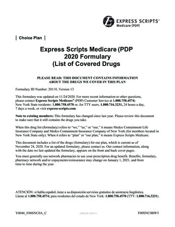
Power Supply AdjustmentsVs AdjustmentVs Test PointVa Test PointVa Adjustment17Each plasma panel has a unique voltage setting required to display a pictureproperly and maintain long life. Incorrect adjustment of the power supply can createpicture errors. Whenever a power supply board is replaced the new board must beadjusted to match the panel values shown on the sticker.If a power supply board is replaced it is imperative that the new power supply beadjusted to match the existing panel settings. Incorrect adjustment can cause thepicture to be too dark or too bright. Extreme misadjustment can greatly reducepanel life.Locations of the test points and adjustments on a typical SMPS power supply.These adjustments must be performed when the SMPS or the panel is replaced.17
Power Supply Protection CircuitsOver Voltage ProtectionThe Power Supply PCB has an Over Voltage Protection circuit as well as a regulator circuit. It isdesigned so that when an Over Voltage condition occurs in any part of the power supply it doesnot affect another output stage. The following table shows the Over Voltage specifications. Theunit must be unplugged to reset this error.Intermittent shutdown may be caused by an over-voltage condition.ItemOver Voltage PointVA (typically 75VDC)94VDCD6VDC8.2VDCD3.3VDC4.7VDCOver Current ProtectionFor this Power Supply PCB, if a short circuit occurs on either the VS, VA, 12V, 6V or 3.3V lines,the SMPS stops operating, but should not fail. When the short circuit is removed from the sourceline, the Power Supply will operate normally again.18Over Voltage ProtectionThe Power Supply PCB has an Over Voltage Protection circuit as well as aregulator circuit. It is designed so that when an Over Voltage condition occurs in anypart of the power supply it does not affect another output stage. The following tableshows the Over Voltage specifications. The unit must be unplugged to reset thiserror. Intermittent shutdown may be caused by an over-voltage condition.Over Current ProtectionFor this Power Supply PCB if a short circuit occurs on either the VS, VA, 12V, 6V or3.3V lines, the SMPS stops operating, but should not fail. When the short circuit isremoved from the source line the Power Supply will operate normally again.18
Power Supply Diffusion Example Diffusion is caused by a power supply that is not properly matched to thepanel. Over diffusion is the most common symptom, this is where the SMPS isproviding to much Vs voltage for the panel.19The diffusion problem can be seen using the sweeping test pattern located in thecustomer menu under the burn protection selection. Diffusion is caused by a powersupply that is not properly matched to the panel.Over diffusion is the most common symptom, this is where the SMPS is providing tomuch Vs voltage for the panel.19
Power Supply Diffusion Allow the unit to warm up 15 to 20 minutes tostabilize the SMPS Operation Access the Customer Setup Menu, then Screenburn protection, then Signal Pattern Adjust the Vs voltage while monitoring thescreen. Adjust the Vs voltage up or down, if thediffusion error is not diminished as the voltagechange approaches Δ10 volts the panel needsto be replaced Do not adjust the Vs voltage more than 15VDCfrom the value printed on the panel label.20SMPS adjustments to eliminate the diffusion problem20
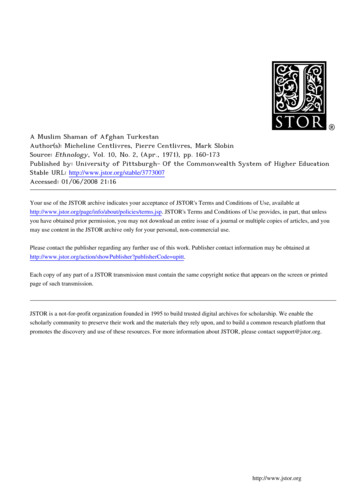
Logic Board Circuit ExplanationTo DataBoardAddressTo ReceiverSustainInitializeTo “X”BoardDigital SignalProcessorDRAMDRAMThe Logic PCB takes the LVDS (Video/Sync) data and converts thatinformation to Addressing and Screen Intensity Control data. The logic boardgenerates the timing signals to trigger the drive and address signals. Theoutput of the Logic board consists of pulses that are synchronized to create thedistinctive X, Y and address signals. These pulses for the most part are usedto trigger the supply voltage to create the distinctive X and Y drive signals.21The luminance and chrominance information for each pixel is processed by the logicboard. The LVDS receiver translates the scrambled RGB video data from the digitalboard. The RGB data is converted to address and sustain values. The address
Repairing LCD TV Guide Plasma TV Repair Guide- Display Fault Troubleshooting Basic LCD TV Repair Secrets Revealed LCD Monitor Repair Guide Vol .1- 10 Trus Repair Case Histories of LCD Monitor SMPS-Switch Mode Power Supply Repair Guide Testing Electronic Components like a Pro- For Beginner Laptop Motherboard Repair Course Laptop Repair Video Collection . 2 2 Table of Contents New