Transcription
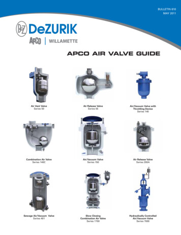
BULLETIN 610MAY 2011APCO AIR VALVE GUIDEAir Vent ValveSeries 50Air Release ValveSeries 55Air/Vacuum Valve withThrottling DeviceSeries 140Combination Air ValveSeries 140CAir/Vacuum ValveSeries 150Air Release ValveSeries 200ASewage Air/Vacuum ValveSeries 401Slow ClosingCombination Air ValveSeries 1700Hydraulically ControlledAir/Vacuum ValveSeries 7000
Theory and Use of Air ValvesEngineers: Air Release Valves and Air/Vacuum Valves are essential components to total pipeline design, not accessory items. Withoutthese essential valves, pipeline capacity will be reduced 5 to 10% or more due to air pocket built up in the line. This reduced capacitymay go unnoticed because air is an invisible culprit in pipelines.Efficiency: Not only will pockets of air rob precious line capacity, but entrapped air will also rob precious electrical energy. The pumpwill have to operate at a higher head to overcome the constricted flow. The elimination of air pockets minimizes the problem and greatlyimproves the pipeline efficiency.Economy: Air Release Valves and Air/Vacuum Valves are of fairly simple construction and are not expensive. APCO’s years of experiencehave proven almost without exception that the cost of air valves is less than one percent of the total installed pipeline cost.Air Release Valves represent low cost insurance for protection of expensive pipelines. Furthermore, the Air Release Valves pay forthemselves by eliminating air pockets and maximizing the capacity and operating efficiency of the pipeline. Additionally, protectionagainst pipeline damage will also occur because it is a well known fact that air pockets are a major encouragement to surge pressuresand water hammer in a pipeline.There Are Two Types of Air Valves1. Air Release Valves2. Air/Vacuum ValvesTypically With Small Orifice 1/2" Diameter or SmallerTypically With Large Orifice 1/2" Diameter Or LargerWhen These Two Valves Are Combined We Have3. Combination Air Valves or DoubleOrifice Air ValvesSelecting Orifice Sizes for Air Release ValvesFor many decades sizing orifices for Air Release Valves has been a mystery. Air entrapped in pipelines is an invisible culprit and noquantitative means exist to determine the precise amount of entrapped air in a flooded transmission pipeline. Also there is no positivemeans to quantify the volume of liberated air (from the media), which will accumulate and must be vented from each high point.APCO has solved the mystery.Variables such as: Source of Media – Pressure differential across the pump – operating pressure – plus pressure/temperaturefluctuations along the transmission line, will dictate the amount of air released from the media accumulating at each high point.Air Release Valves discharge air (which has accumulated inside the valve) from the high point. Generally, Air Release Valves are notconstantly discharging air during system operation, but only discharge intermittently as air accumulates at the high point.Based on the preceding and more than 75 years application experience, APCO developed and recommends the following criteriabe used:1. Use 2% of the media volume divided by the number of high points as the minimum amount of entrapped air.2. Consider this volume as the basis for the amount of air to be discharged from each high point.amount of air to be discharged, cfm flow capacity in gpm x 2% or FLOW CAPACITY IN GPM7.48(As Defined and Recommended)374Note: If the intersection of the Venting Capacity, (CFM) andOperating Pressure (PSI) lies between orifice curve, use thelarger orifice.How to Select and Size an Air ReleaseValve When a Specific Venting Capacity isRequiredA. Enter graph with pressure in the system andthe venting capacity required.B. R ead off nearest orifice diameter to intersectionof pressure and capacity lines on graph.C. Enter table next page with orifice diameter andselect valve which can use this orifice diameter atthe pressure involved.Pressure Differential Across Valve in P.S.I.3. U pon determining the operating pressure of the system, refer to the APCO Venting Capacity Graph for Air Release Valve Orificethen Table of Orifice Sizes to select Model and Size.18,700Example: A pipeline actual flow capacity of 18,700 GPM and operating at 150 psi. Amount of air to be discharged 50 CFM374Using the Venting Capacity Graph for Air Release Valves,Venting Capacity Graph For Air Release Valves50 CFM and 150 psi will intersect the 3/16 orifice curve.11Orifice Sizes 32 16 3 32 1 8 5 323 167 321 4 5 16 3 87 161 2Then, on the Table of Orifice Sizes, Model 200A with3/16 orifice can be selected with the appropriate inlet size.Venting Capacity In Cubic Feet Of Free Air Per Minute2 2011 DeZURIK, Inc.
1. Air Release ValvesAir Release Valves are hydro-mechanical devices which automatically vent small pockets of air as they accumulateat high points in a system while the system is operating and pressurized. By understanding problems associatedwith air pockets in a system we can appreciate that Air Release Valves (ARV) are devices ideally suited to eliminatethose problems. As a function of physics, entrained air will settle out of the liquid being pumped and collect athigh points within the system. If provisions are not made to remove this air from high points, pockets of air willcollect and grow in size. Air pocket growth will then gradually reduce the effective liquid flow area, creating athrottling effect as would a partially closed valve. The degree which flow is reduced and some ensuing problemsare described in the following.Often the velocity of the liquid will remove air bubbles if the pipeline slopes upward to lodge at a high point.But, if the pipeline is fairly flat, the ceiling of the pipe is very rough or the pipeline slopes downward, the velocitymay not be sufficient to keep the air pockets (bubbles) moving. Additional Air Release Valves (ARV’s) must beinstalled to prevent this ‘throttling’ effect.In extreme cases it is possible for an enlarging pocket of air collecting at a high point within a system to create anair block to a degree where the flow of fluid virtually stops. In this severe case an air problem is easily detected andinstallation of ARV’s at the high points will remove the restrictive pockets of air to restore system efficiency.Compound LeverAPCO Series #200AAnother serious consequence is sudden movement of these air pockets causing rapid velocity changes of the liquidbeing pumped. The dynamics involved in velocity change can be substantial, resulting in high pressure surges and otherdestructive phenomena in the pipelines.Therefore, problems with air entrapped in a system can range from mild, but costly, to severe anddestructive. The design engineer should prevent accumulation of air by installing ARV’s on all high pointsof a system.Air Release Valve OperationThe valves installed on a high point of the system will fill with liquid, shut off, and be subjected to systempressure. During system operation small particles of air will separate from the liquid and enter the valve.Each particle of air will displace an equal amount of the liquid within the valve and lower the liquid levelrelative to the float. When the liquid level lowers the float will drop. This action opens the valve orifice andallows the air which has accumulated in the upper portion of the valve to be released to atmosphere. As airis released, the liquid level within the valve once again rises, lifting the float and closing the valve orifice. Thiscycle repeats itself as often as air accumulates in the valve.Simple LeverAPCO Series #55The ability of the ARV to open and release accumulated air under pressure is achieved through the use of a leveragemechanism. When the float is no longer buoyant, this mechanism (plus the weight of the float) produces a greater forceto open the valve than to hold the valve closed. Accordingly, the higher the system pressure the smaller the orificediameter must be to allow the valve to open and release accumulated air. Conversely, with the same valve and alower system pressure, a larger diameter orifice can be used to release accumulated air.Note: ARV’s are intended to release air as it accumulates at high points during system operation. They arenot normally recommended for vacuum protection nor to vent large volumes of air when filling large diameterpipelines, because inherently ARVs have small orifices, usually less than 1/2" diameter – Air/Vacuum Valves havemuch larger orifices for this purpose. However, ARV’s will permit small quantities of air to re-enter under negativeconditions and if objectionable, specify ARV’s with a vacuum check.Ask for APCO Computer Software Programs for sizing and specifying your valves.Table of Orifice SizesSimple Lever Seat DetailNOTE: Please specify if pressures are below 20 psi.ModelInlet Size50Maximum Orifice Sizes Which Can Be Used With The Following Pressures102550751001251502002503005008001500.5", .75", 1"12.7, 19.05, 6.125"3.2.125"3.2.125"3.2XXXXXX200A1", 2"25.4, 2", 3", 4"50.8, 76.2, .25"6.4.187"4.8.156"4.156"4XXX4502", 3", 4"50.8, 76.2, 12.7.437"11.437"11.437"11XXXInchMillimeterStandard Orifices Are In Gray3
2. Air/Vacuum ValvesAn Air/Vacuum Valve (AVV) is float operated, having a large discharge orifice equal in size tothe valve inlet. This valve allows large volumes of air to be exhausted from or admitted into asystem as it is filled or drained.Used on pipelines, the following conditions would prevail:Prior to filling, a pipeline is thought to be empty, but this is not true. In reality it is filled with air.This air must be exhausted in a smooth uniform manner to prevent pressure surges and otherdestructive phenomenon from occurring in the pipeline.Additionally, air must be allowed to re-enter the pipeline in response to a negative pressure toprevent a potentially destructive vacuum from forming. Even in those instances where vacuumprotection is not a primary concern, air re-entry is still essential to efficiently drain the pipeline.At locations where column separation is anticipated an Air/Vacuum Valve will allow air to enter,preventing a destructive vacuum from forming which is as damaging as pressure surges.Air/Vacuum Valve OperationAs the pipeline is filled, air is exhausted to atmosphere through an AVV mounted on eachhigh point. As air is exhausted from the pipeline, water will enter the valve and lift the float toclose the valve orifice. The rate of air exhausted is a function of pressure differential, whichdevelops across the valve discharge orifice. This pressure differential develops as water fillingthe pipeline compresses the air sufficiently to give it an escape velocity equal to that of theincoming fluid. Since the size of the valve controls the pressure differential at which the air isexhausted, valve size selection is a very important consideration.4" Thru 30"APCO Series #150Any time during system operation, should internal pressure of the pipeline approach a negativevalue due to column separation, draining of the pipeline, power outage or pipeline break, thefloat will immediately drop away from the orifice and allow air to re-enter the pipeline. Airre-entry during water column separation will prevent a vacuum. This protects the pipelineagainst collapse. The size of the AVV will dictate the degree to which a vacuum is prevented,therefore correct valve size selection is necessary. The AVV, having opened to admit air into thepipeline in response to a negative pressure, is now ready to exhaust air again. This cycle willrepeat as often as necessary.During system operation and while under pressure, small amounts of air will enter the AVVfrom the pipeline and displace the fluid. Eventually, the entire AVV may fill with air, but it willnot open because the system pressure will continue to hold the float closed against the valveseat. To reiterate, an AVV is intended to exhaust air during pipeline fill and to admit air duringpipeline drain. It will not open and vent air as it accumulates during system operation – AirRelease Valves are used for this purpose.See Bulletin 601Characteristics of Air Flow Through an Air/Vacuum Valve OrificeLinear velocity of air, discharged through the orifice of an Air/Vacuum Valve increases aspressure differential across the orifice increases, until reaching a maximum velocity ofapproximately 300 feet per second. This maximum air velocity occurs at about 7 psi andremains a constant thereafter, regardless of further increase in the pressure.Explanatory Note: Unlike liquids, the volume of air that fills one cubic foot at atmosphericpressure will occupy a progressively lesser volume as its pressure increases.The amount of air actually expelled through the orifice continues to increase indefinitely asthe pressure increases. While there is no further increase in the escape velocity beyond 7psi approximately, the air escaping at this velocity itself becomes progressively denser andrepresents a greater amount when expressed in cubic feet at atmosphere, ie. C.F.F.A.M.To accommodate this condition, flow of air is always referred to in cubic feet of free air perminute (C.F.F.A.M.) even though the air under consideration is usually at some other pressurethan atmosphere.41/2" Thru 3"APCO Series #140
3. Combination Air ValvesAs the name implies, Combination Air Valves (CAV) have operating features
Economy: Air Release Valves and Air/Vacuum Valves are of fairly simple construction and are not expensive. APCO’s years of experience have proven almost File Size: 1MBPage Count: 12