Transcription
29/01/13 (rev 2)APCO AviationSetting Future StandardsFactory: 7, Chalamish Street - Industrial Park - Caesarea 38900 ISRAEL www.apcoaviation.com
www.apcoaviation.comCONTENTS:1 DISCLAIMER OF LIABILITY .52 CONSTRUCTION .53 MATERIALS.54 HIT VALVES (High speed In-Take).65 BUTT HOLES (Velcro closure on trailing edge tip) .66 TRIMMING .77 HARNESS.78 SPREADERS .79 RISERS.810TRIMMERS .1011EMERGENCY PARACHUTE ATTACHMENT .1112INSPECTION.1112.1 GENERAL.1112.2 BRAKE SETTING .1112.3 FIRST CHECK AND PREFLIGHT INSPECTION.1212.4 REGULAR INSPECTION CHECKS .1212.5 LINE MAINTENANCE .1213LAUNCHING .1313.1 LAYOUT.1313.2 ALPINE LAUNCH OR FORWARD LAUNCH .1313.3 STRONG WIND AND REVERSE LAUNCH.1413.4 TOW OR WINCH LAUNCHING .1414FLIGHT TECHNIQUES .1414.1 FLYING SPEED .1414.2 THERMAL FLYING .1514.3 ASYMMETRIC COLLAPSE .1514.4 CRAVAT .1514.5 FRONT STALL OR SYMMETRIC COLLAPSE .1514.6 B-STALL .1514.7 BIG EARS .1614.8 DEEP STALL OR PARACHUTAL STALL .1614.8.1 Signs of parachutal stall.1614.8.2 Exit from parachutal stall.1614.9 SPIRAL DIVES .1714.10STRONG TURBULENCE .1714.11STEERING NOT FUNCTIONING.1715LANDING.1815.1 TREE LANDING.1815.2 WATER LANDING .1815.3 LANDING IN TURBULENCE .1816PACKING .1817MAINTENANCE & CLEANING .1918STORAGE .1919DAMAGE .1920GENERAL ADVICE .1921PLAY42 SKETCHES AND CERTIFICATION .2021.1 SKETCHES.2021.2 CERTIFICATION.2222PLAY42 MK II SKETCHES.23.Page 2 of 24
www.apcoaviation.com!!! WARNINGThis is not a training manual. Attempting to fly this or any other paragliderwithout proper instruction from a qualified professional instructor is extremelydangerous to yourself and bystanders.Apco Aviation's gliders are carefully manufactured and inspected at the factory.Please use the glider only as described in this manual. Do not make any changes tothe glider. AS WITH ANY SPORT - WITHOUT TAKING THE APPROPRIATEPRECAUTIONS, PARAGLIDING CAN BE DANGEROUS.Page 3 of 24
www.apcoaviation.comGLIDER TECHNICAL DATASIZE42464235.414.612.15.14.1140 – 240 / 340 UL8.43.470.66496CellsArea m2Area (projected) m2Span (incl. Stabiliser) mSpan (projected) mAspect RatioAspect Ratio (projected)Pilot and Passenger Weight KgWeight of Canopy KgRoot Cord mTip Cord mTotal length of line used mLINESTop FloorMiddle FloorLower FloorLower A,B (UL)Lower C,D,St (UL)Brake deSuperaramideSuperaramideSuperaramideDiameter / UL1,2 mm / 1,5 mm1.8 mm2,3 mm2,5 mm1,9 mmStrength / UL110 kg / 150 kg230 kg280 kg450 kg320 kgDyneemaPolyester1,1mm2.0mm95kg85kgFABRICSail ClothRib ReinforcementWarranty46gr/m2 "Zero Porosity" Ripstop Nylon180gr/m2 Mylar (Trilam)3 Years / 250 hoursGLIDER PERFORMANCE DATAV-min @ optimum wing loadV-trim @ optimum wing loadV-max @ optimum wing loadMin Sink @ optimum wing load23 km/h38 km/h45 km/h1.1 m/sGLIDER CERTIFICATION DATAPLAY 42 (42)BIPLACEPage 4 of 24
www.apcoaviation.com1 DISCLAIMER OF LIABILITYTaking into consideration the inherent risk in paragliding, it must be expresslyunderstood that the manufacturer and seller do not assume any responsibility foraccidents, losses and direct or indirect damage following the use or misuse of thisproduct.APCO Aviation Ltd. is engaged in the manufacture and sale of hang gliding,paragliding, motorized para/hang gliding and emergency parachute equipment.This equipment should be used under proper conditions and after proper instructionfrom a qualified instructor. APCO Aviation Ltd. has no control over the use of thisequipment and a person using this equipment assumes all risks of damage or injury.APCO Aviation Ltd. disclaims any liability or responsibility for injuries or damagesresulting from the use of this equipment.The glider is designed to perform in the frame of the required class as certified byAFNOR / CEN2 CONSTRUCTIONThe glider is constructed with a top and bottom surface, connected by ribs. One topand bottom panel, together with the connecting ribs is called a cell. Each cell has anopening on the lower front part. The cells fill with air forcing the panels to take theshape dictated by the airfoil (rib) section. On either side the wing ends in a stabilizeror wing tip, which provides straight-line (Yaw) stability and produces some outwardforce to keep span-wise tension. The front part of the ribs is made from Trialm Mylarto keep the leading edge shaped at high speeds and in turbulent air. It also improvesthe launch characteristics of the glider. The line hook-up points are made ofDyneema or Nylon tape.3 MATERIALSThe glider is made from tear resistant Ripstop Nylon cloth, which is P.U. coated tozero porosity and then siliconized to give the fabric high resistance to the elements.Different cloth is used for the top, bottom and ribs due to their different functions. Thelines are made of superaramide covered with a polyester sheath for protectionagainst UV, wear and abrasion. The bottom section of the brake lines is made ofpolyester because of its better mechanical properties. The carabiners that attach thelines to the risers are made of stainless steel.Page 5 of 24
www.apcoaviation.com4 HIT VALVES (High speed In-Take)The Play 42 is equipped with an Active HIT Valve system (patent pending) toimprove the overall performance and safety of the wing especially during acceleratedflight.The valve system allows maximum inflow of air when the glider acquires a lowerangle of attack while accelerated. HIT valves open and close in flight to increase theinternal pressure of the glider.For the valves to work properly it is important to keep them wrinkle free especially insub zero temperatures. Make sure the valves are lying flat and are in the closedposition when you fold the glider. Before launch the pilot should check all the valvesand verify that they are flat and cover the entire area of the mesh opening. Creasedand wrinkled valves will not adversely affect the safety of the wing.5 BUTT HOLES (Velcro closure on trailing edge tip)In order to empty sand and small stones from the glider simply shake out the debristowards the wing tip and open the Butt holes (Velcro closure on trailing edge tip)and pull out the cloth tongue outside to empty. Do not forget to close the Butt holesafterwards.Page 6 of 24
www.apcoaviation.com6 TRIMMINGAll Apco gliders are trimmed for optimum performance and safety. It is very importantnot to re-trim or tamper with any of the lines or risers as this may alter theperformance and safety of the glider. Trimming of the brake line should be done inaccordance with this manual and carefully checked before flying.7 HARNESSAll of Apco's gliders are developed with the use of ABS (Automatic Bracing System)type harnesses without cross bracing. We recommend the use of an ABS harnesswith all our gliders. All certified harnesses can be used with our gliders. For bestsafety and performance we recommend an Apco harness equipped with a Maydayemergency parachute.CAUTION:CROSS BRACING THAT HAS BEEN ADJUSTED TOO TIGHTLY CAN AFFECT THE HANDLING OF AGLIDER, AND MAY NOT NECESSARILY LEAD TO GREATER SAFETY. APCO GLIDERS AREDEVELOPED AND TESTED WITHOUT THE USE OF CROSS BRACING. USING AN ABS HARNESSWITH CHEST STRAP SET AT THE SPECIFIED WIDTH (CHECK THE AFNOR STICKER ON YOURGLIDER) WILL RESULT IN THE HIGHEST PASSIVE SAFETY ON YOUR GLIDER.It is recommended to use a certified rescue parachute when flying. Attaching therescue parachute should be done in accordance with the recommendation of theharness and reserve parachute manufacturer. The attachment should be performedand inspected by a qualified person.8 SPREADERSTandem flying requires the use of spreaders. The two most commonly used types aresoft spreaders and spreader bars. The choice of which spreader to use is up to thepersonal preference of the pilot.Page 7 of 24
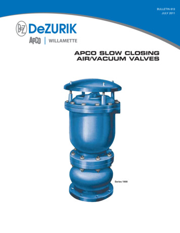
www.apcoaviation.com9 RISERSThe Play42 MKII risers have two brake pulley positions; higher or lower (seedrawing). The factory default is the higher position. For paramotor use or for otherreasons you may alter this brake position. To do so, follow these steps:1. Mark the brake handle knot position using a pen.2. Open the brake line knot, remove the handle and brake line from the pulley.3. Unhook the pulley from the webbing on the riser and hook it in the lowerposition.4. Thread the brake line through the pulley.5. Re-knot the brake line 15 CM lower from the pen marking you made in step 1.6. Repeat these steps for the second riser.Note: always test-inflate you glider after adjusting brake position.The Play42 is supplied with a split A riser. The first A-riser is attached to theoutermost A line (A5). The second A-riser is attached to the central two A lines (A1 &A3). This is to facilitate big ears or tip tucks. At no time should the pilot change therisers or use risers not intended for this specific glider as this will affect theperformance and safety of the glider.Page 8 of 24
www.apcoaviation.comPage 9 of 24
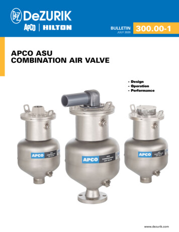
www.apcoaviation.com10 TRIMMERSThe Play42 and Play42 MKII risers are equipped with replaceable trim tabs foraccelerated flight. The neutral setting is when the A/B/C/D risers equal in length. Werecommend the neutral position for take off and landing. To accelerate the glider,Page 10 of 24
www.apcoaviation.comopen the trimmers. For flat turns in thermals with light brake pressure, close thetrimmers fully.If your trim tabs are worn out simply fray the safety stitch, take out the trimmerwebbing and replace it with new APCO trimmer webbing. After re-installing thetrimmer webbing make sure to sew a safety stitch at same distance as the original inorder to have the full trimmer range.11 EMERGENCY PARACHUTE ATTACHMENTIt is recommended to use a certified rescue parachute when flying. Attaching therescue parachute should be done in accordance with the recommendation of theharness and reserve parachute manufacturer.12 INSPECTION12.1 GENERALPilots, please insure that your glider has been test flown and checked by your d
Apco Aviation's gliders are carefully manufactured and inspected at the factory. Please use the glider only as described in this manual. Do not make any changes to .