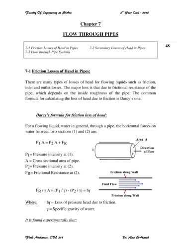
Transcription
APCO FlangesSection 8FlangesThis section contains extracts from American and Britishspecifications applicable to forged steel flanges.Subsections and topicsFlanges - General Information2ASME/ANSI Flanges (incl. MSS SP-44 and API 605)4Weld Neck Flanges - Welding Ends (ASME/ANSI)5Ring Joint Facings - ASME/ANSI B16.5 & B16.47Weld Neck Flanges - ANSI B16.5Slip On Flanges - ANSI B16.5Blind Flanges - ANSI B16.5 & ASME B16.47 (MSS SP-44)1724, 4632Threaded Flanges - ANSI B16.539BS 3293 Flanges (Weld Neck and Slip On NPS 26)55BS 4504 Circular Flanges - General60Weld Neck Flange - Welding Ends62Flange Facings - BS 450462Flange Drilling Details - BS 450464Plate Flanges (Code 101) - BS 450465Weld Neck Flanges (Code 111) - BS 450466Slip On Flanges (Code 112) - BS 450468Threaded Flanges (Code 113) - BS 450469Blank Flanges (Code 105) - BS 450470BS 10 Flanges71Pressure/Temperature Ratings (ASME/ANSI)73PageASME B16.5-1996 - Pipe Flanges and Flanged FittingsNPS 1 /2 through NP 244(general)10 to 45ASME B16.47-1996 - Large Diameter Steel FlangesNPS 26 through NPS 60(Covers MSS SP-44 and API 605 flanges)MSS SP-44 1996 - Edition, Steel Pipeline Flanges(Covered by ASME B16.47-1996 Series A)API Standard 605 - Cancelled(Covered by ASME B16.47-1996 Series B)BS 10 : 1962 - Specification for Flanges and Bolting forPipes, Valves, and FittingsBS 3293 : 1960 (incorporating amendment 1972) Specification for Carbon Steel Pipe Flanges (over 24 inchesnominal size) for the Petroleum Industry4(general)46 to 54BS 4504 : Section 3.1 : 1989 (incorporating amendments) Circular Flanges for Pipes, Valves and Fittings (PNdesignated), Section 3.1 Specification for Steel FlangesISO 7005-1 : 1992 (E), Metallic Flanges - Part 1: SteelFlanges (this is substantially the same as BS 4504)Tel: 86-431-88546619610, 46Lap Joint Flanges - ANSI B16.5Specifications covered in this SectionAPCOPagesFax: 86-431-88546621E-mail: sales@apcopipe.com46 to 5051 to 54715560601
APCO FlangesFlanges - General InformationA Flange is a method of connecting pipes, valves, pumps and other equipment to form apipework system. It also provides easy access for cleaning, inspection or modification.Flanges are usually welded or screwed into such systems and then joined with bolts.Flange TypesThis flange is circumferentially welded into the systemat its neck which means that the integrity of the buttwelded area can be easily examined by radiography.The bores of both pipe and flange match, whichreduces turbulence and erosion inside the pipeline.The weld neck is therefore favoured in criticalapplicationsThis flange is slipped over the pipe and then filletwelded. Slip-on flanges are easy to use in fabricatedapplications.This flange is used to blank off pipelines, valves andpumps, it can also be used as an inspection cover. Itis sometimes referred to as a blanking flange.This flange is counter bored to accept the pipe beforebeing fillet welded. The bore of the pipe and flange areboth the same therefore giving good flowcharacteristics.This flange is referred to as either threaded orscrewed. It is used to connect other threadedcomponents in low pressure, non-critical applications.No welding is required.These flanges are always used with either a stub endor taft which is butt welded to the pipe with the flangeloose behind it. This means the stub end or taft alwaysmakes the face. The lap joint is favoured in lowpressure applications because it is easily assembledand aligned. To reduce cost these flanges can besupplied without a hub and/or in treated, coatedcarbon steel.This is a method of ensuring leak proof flangeconnection at high pressures. A metal ring iscompressed into a hexagonal groove on the face ofthe flange to make the seal. This jointing method canbe employed on Weld Neck, Slip-on and BlindFlanges.2APCOTel: 86-431-88546619Fax: 86-431-88546621E-mail: sales@apcopipe.com
APCO FlangesFlanges - General InformationSpecificationsRefer to page 1 for a list of flange specifications (with page references) covered in this Section.ManufactureSummary of materials used for flangesForging (ASTM A 182)Plate (ASTM A 240) 4Bar5Casting6ASME/ANSIB16.5 ASME B16.47Series A(or MSS SP-44 1) ASME B16.47Series B( or API 605 2) BS4504BS3293BS 10 3 Notes1 MSS SP-44 flanges are designated Series A flanges in ASME B16.47.2 API 605 has been cancelled. API 605 flanges are designated Series B flanges in ASME B16.47.3 BS 10, although obsolete, remains in use for light weight economy stainless steel flanges.4 Within specification ANSI B16.5, plate can only be used to provide blind flanges.5 Most small BS 10 flanges are made from bar.6 Castings are not included in this manual. Materials. Most standards specify the materialfrom which the flange is produced. The purchasershould specify the exact requirements.Flange Sizes. All sizes and grades compatible tostandard pipe ranges and wall thicknesses(pressure ratings) are available. The table belowprovides a summary.Flange Face. There are various faceconfigurations for flanges. Typically: flat face,raised face, tongue and groove, ring joint. Face Finish. The finish on the face of a flange ismeasured as an Arithmetical Average RoughnessHeight (AARH). The finish is determined by thestandard used. For example, ANSI B16.5specifies face finishes within a range 125AARH 500AARH (3.2 Ra to 12.5 Ra). Other finishes areavailable on request, for example 1.6 Ra max,1.6/3.2 Ra, 3.2/6.3 Ra or 6.3/12.5 Ra. The range3.2/6.3 Ra is most common.Summary of flange sizes specified by common standardsASME/ANSIB16.5BS 3293 NPS 26 NPS 26 NPS 26Class 00As above150-2500150-25003Class (lb)150-900300-900As above300-900Flange TypeWeld NeckSlip-onBlindLap JointSocket WeldThreadedFlat/Raised FacingsRing Joint FacingsOther FacingsSpecificationsASME B16.47BS 4504Series B(ISO 7005-1)(or API 605 2)Nominal Pipe SizesDN 10 to NPS 26DN 4000Nominal Pressure (Class)Class (lb)PN (bar)75-9002.5-402.5-40300-9002.5-406-40 3N/A6-40As aboveAs above300-9002.5-402.5-40ASME B16.47Series A(or MSS SP-44 1)-Class (lb)150-600150-600As above300-600-Notes1 MSS SP-44 flanges are designated Series A flanges in ASME B16.47. It also covers flanges in the range NPS 12 to 24,these being equivalent to ASME/ANSI B16.5 flanges in the same range (except for the addition of NPS 22 in MSS SP-44).2 API 605 has been cancelled. API 605 flanges are designated Series B flanges in ASME B16.47. Ranges quoted are basedon ASME B16.47 Series B.3 Dimensions not covered in this summary.APCOTel: 86-431-88546619Fax: 86-431-88546621E-mail: sales@apcopipe.com3
APCO FlangesASME/ANSI B16.5-1996 and B16.47-1996American national standards ASME/ANSI B16.5 and B16.47 together cover pipe flangesup to NPS 60 (NPS 48 is the largest detailed in this summary). ASME/ANSI B16.47 coverstwo series of flanges, Series A which is equivalent to MSS SP-44 (the 1996 Edition ofMSS SP-44 complies with B16.47 tolerances), and Series B which is equivalent to API605 (API 605 is now cancelled).Dimensions and TolerancesTolerances on flange dimensions (ASME/ANSI B16.5 and B16.47, and MSS SP-44)DimensionToleranceRangeinmmGeneral and Blind Flanges (For blind flange dimensions see page 23 for B16.5, page 46 for B16.47Series A / MSS SP-44 and page 51 for B16.47 Series B / API 605): 0.03 0.76 NPS 24G (raised face diameter)I (bolt hole diameter)J (bolt circle diameter)Centre to centre ofadjacent bolt holesEccenticity of bolt circleand machined facingdiameters NPS 26, with0.06 in raised face NPS 26, with0.25 in raised faceAll 0.08 2.03 0.04 1.02AllNo tolerance in B16.5 or B16.47 0.06 1.52All 0.03 0.761 NPS 2 /2 0.03 0.76 NPS 3 0.06 1.52Weld Neck Flanges1 (For dimensions see page 10 for B16.5, page 46 for B16.47 Series A / MSS SP-44 andpage 51 for B16.47 Series B / API 605): NPS 4 0.06 1.52D (overall length)Thickness of hubNPS 5 to 10 0.06, -0.12 1.52, -3.05NPS 12 to 24 0.12, -0.18 3.05, -4.57 NPS 26 0.19 4.83All 87.5% of pipe nominal wall thicknessSlip on (see page 17), Lap Joint (see page 32 for dimensions) and Socket Welding (see page 30 fordimensions) Flanges: NPS 10 0.03, -0.0 0.76, -0.0B (inside diameter, orbore) NPS 12 0.06, -0.0 1.52, -0.0Threaded Flanges (see page 40 for dimensions):B (counterbore) NPS 10(Not applicable for NPS 12Class 150 lb) 0.03, -0.0 0.76, -0.0 0.06, -0.0 1.52, -0.0Ring Joint Facing (See page 6 for dimensions; see page 9 for tolerances)Note1 See page 5 for weld neck welding end dimension and tolerance data.4APCOTel: 86-431-88546619Fax: 86-431-88546621E-mail: sales@apcopipe.com
APCO FlangesGeneral - ASME/ANSI B16.5 & B16.47Weld Neck Flanges - Welding EndsASME/ANSI B16.5 (NPS 1/2 to 24) Weld Neck FlangeBevel (with no backing ring) for Wall Thicknesses (t)from 0.19 to 0.88 in (4.83 to 22.35 mm).ASME/ANSI B16.5 (NPS 1/2 to 24) Weld Neck FlangeBevel (with no backing ring) for Wall Thicknesses (t) 0.88 in (22.35 mm).ASME B16.47 and MSS SP-44 ( NPS 24) Weld NeckFlange Bevel (with no backing ring) for WallThickness (t) 0.19 to 0.88 in (4.83 to 22.35 mm).ASME B16.47 and MSS SP-44 ( NPS 24) Weld NeckFlange Bevel (with no backing ring) for WallThicknesses (t) 0.88 in (22.35 mm).Tolerances on welding end dimensions (ASME/ANSI B16.5 and B16.47, and MSS SP-44)DimensionE (outside diameter atwelding end)B (inside diameter offlange)t (thickness at weld bevel)Range NPS 5NPS 6 to 24 NPS 26B NPS 10B NPS 12 to 18B NPS 20Allin 0.09, -0.03 0.16, -0.03 0.21, -0.06 0.03 /-0.03 0.12, -0.06Tolerance 87.5%mm 2.29, -0.76 4.06, -0.76 5.33, -1.52 0.76 0.76 3.05, -1.52Notet Nominal wall thickness of the pipe. Additional thickness at the weld bevel (up to 0.5 x t) may be provided on the insideor outside diameter (or partially on both) of the hub if it is used with light walled higher strength pipe. Hub diameter, F, mayalso be increased.APCOTel: 86-431-88546619Fax: 86-431-88546621E-mail: sales@apcopipe.com5
APCO FlangesRing Joint Facings - ASME/ANSI B16.5 & B16.47NoteValues for minimum flange thickness,C, and overall length, D, are detailed inthe flange tables.For ring joint tolerances see page 9.Class (lb)15030040060090015002500Nominal Pipe Size (NPS)Groove/RingNumberRing joint facing dimensions - ASME/ANSI B16.5and B16.47 Series A (MSS SP-44) and Series B (API 605)ASME/ANSI B16.5 covers NPS 1/2 to 24:11/2R11/2133/4R12/2R13/413/21R1511R161 /411/411/211/211/411/2Use Class 1500 for sizes 2 1/21Use Class 600 for sizes 31/21R163/4R16R17R18R1811 /41R18R19R201R201 /211/42R21R2222R2311 /22R23R241R252 /221/2R2621/226R13R14/4APCOTel: 0127.005.250133.35Fax: 00101.60Depth 0.760.030.76E-mail: sales@apcopipe.com
APCO FlangesRing Joint Facings - ASME/ANSI B16.5 & B16.47Class (lb)15030040060090015002500Nominal Pipe Size (NPS)R27-23231/213 /2Use Class 600 for sizes 31/2132 /221/2R28R29R30-2R31323R313R32R33R3413 01010R5310R5310APCOGroove/RingNumberRing joint facing dimensions - ASME/ANSI B16.5and B16.47 Series A (MSS SP-44) and Series B (API 605) (Continued)Tel: 86-431-88546619R54Fax: 86-431-88546621RaisedFaceGrooveFacePitchDiameter .3448.740.46911.910.46911.910.65616.66E-mail: 030.760.030.760.030.760.030.760.06
Face Finish. The finish on the face of a flange is measured as an Arithmetical Average Roughness Height (AARH). The finish is determined by the standard used. For example, ANSI B16.5 specifies face finishes within a range 125AARH - 500AARH (3.2 Ra to 12.5 Ra). Other finishes are available on request, for example 1.6 Ra max, 1.6/3.2 aR , 3.2/6.3 Ra or 6.3/12.5 Ra. The range . 3.2/6.3 Ra is most .