Transcription
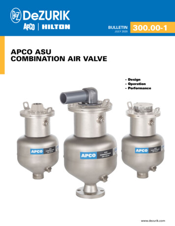
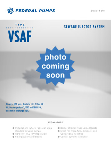
2008Sewage Combination Air ValveSERIES 440 SCAVSewage Air Release ValveSERIES 400 SARVSewage Air Vacuum ValveSERIES 401 SAVVCONCAVE FLOAT* (Patented)Generation IIAIR VALVESSEWAGE AIR VALVESBULL 4 0 0ETINEditionVALVE & PRIMER CORPORATION1420 WRIGHT BLVD. SCHAUMBURG, IL 60193-4599847.524.9000 FAX:847.524.9007 800.323.6969website: www.apcovalves.com e-mail: factory@apcovalves.com1031
GENERATION IIAPCO AIR VALVES FORSEWAGE PIPELINE SYSTEMSEFFECTS OF AIR in a pressurized closed-pipeline system must be recognized. An air pocket will decrease thecross sectional area and increase frictional pressure loss. The combined loss for two-phase flow (air & water)is always greater than the pressure loss for each phase flowing alone. Thus, air in a pipeline increases systemflow resistance and increases system head against which pumps must operate.AIR MAY ENTER A PIPING SYSTEM IN MANY WAYS:(1) Air in the pipeline when initially filled may not be completely purged.(2) Air may be drawn in at a pump inlet by entrainment if the liquid level falls below the inlet elevation.(3) Air in solution (about 2% by volume) will be released at points in the pipeline where the pressureis reduced, especially where the line elevation is close to the hydraulic gradient.(4) Gas created from digested sewage.(5) Air may be drawn in through packings, seals and flanged joints.(6) Air may enter by vortexing at the pump.AIR IN PIPING tends to collect at high points in the line when flow velocities are low. If the air pocketformed is large, part of it will be removed when the velocity increases. This partitioned air may or may not gothrough the system. It all depends on velocity, pipe size, and pipe down-slope. It may only move into thesloping straight section and then return to the summit when the velocity decreases.While it is impossible to totally prevent accumulation of air (or gases) within the piping system, the volumecan be greatly minimized by installing APCO Sewage Air Release Valves.When air is present in a hydraulic pipeline, flows are erratic, unpredictable and have high head losses.Sewage works require Air Release Valves on pipeline high points.All APCO Sewage Valves are furnished for 150 psi. Higher pressures available. Specify if operatingpressure is below 20 psi for a lower durometer seat.BACKFLUSHING ATTACHMENTSOPTIONAL FOR ALL SEWAGE VALVESEXCEPT CUSTOM COMBINATIONSWhile sewage media is standing in the valve body, sediment will attempt settling out at the bottom. This sediment maybe flushed out periodically.After installation, Sewage Valves should be inspected to determine need to backflush approximately once a year.Inspection takes only a few minutes and is simple:1. Shut off the inlet valve.2. Open the blow off valve and observe if fluid drains out the valve body rapidly, flushing is not required.Should heavy suspended solids and grease be anticipated, attachments shown are recommended for ease of flushing.1042
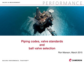
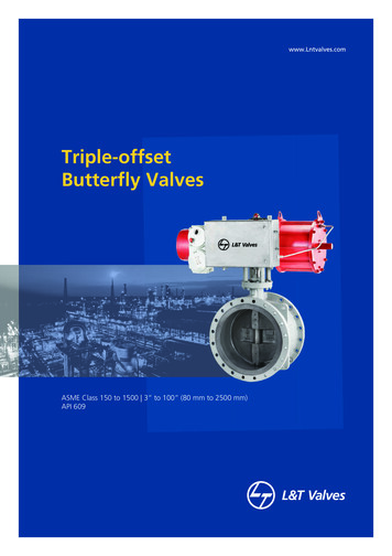
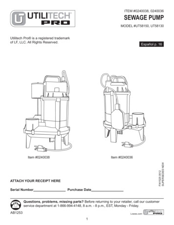
LESeries 440 SCAV4 0 0NITSEWAGE COMBINATION AIR VALVEBUL First in a Single Body No Spills No Spurts ShorterCONCAVE FLOAT*SEWAGE AIR VALVESNow, APCO brings you THE LATEST STATE OF THE ART SewageAir Valve design: a Single Body, Double Orifice “Sewage CombinationAir Valve”.GENERATION II a new generation of Air Valve Design.Field tested under actual operating conditions. Incorporating allfeatures that have made the 400 Sewage Air Release Valves and 401Sewage Air/Vacuum Valves the world’s finest Now in a SingleBody-plus a New Concave Float* - to give even greater performanceand reliability.You no longer need to DIG DEEPER TRENCHES OR BUILDDEEPER VAULTS BECAUSE THE 440 SERIES IS AT LEAST 30%SHORTER THAN OTHER MODELS!Valves that won’t spill or spurt before shutting off. No more messywaste flooded valve vaults to pump out or Pump Station floors tomop up it shuts off drop tight.Take a serious look at GENERATION II - APCO Sewage Valves.Manufactured to our industry’s highest standards providing thehighest efficiency and reliability of any sewage air valve availablein the market today.Generation IIPATENTEDSeries 440 TTACHMENTS4431”2”NPT1”NPT191 2241 291 287954452”2”NPT2”NPT201 22791 2931004473”3”NPT3”NPT231 2291 2111471574494”4”NPT4”NPT231 230111501754566”6”125LB.FLANGE6”3539133 4242297AIR VALVESMODEL SIZE INLET OUTLET1053
SEWAGE COMBINATION AIR VALVE (SINGLE BODY) with two independent orifices!Series 440 SCAV LARGE ORIFICEDOUBLEORIFICELARGEORIFICEFor air out and in(Air/Vacuum Valve function) SMALL ORIFICEFor air release(Under pressure function) ODYCONCAVE FLOAT*TWO MAJOR COMPLAINTS NOW REMEDIEDWITH APCO’S INTRODUCTION OF THE CONCAVE FLOAT*!1. SPILLAGEPeople easily tolerate and are reasonable about water spillage from valvesbut sewage that “nasty stuff” is cause for some Engineers and Users aliketo avoid use of Sewage Air Valves, regardless of need to a system.During the past 30 years, the single most highly objectional complaint aboutthe Sewage Air Valve is, “it spills” or “it spurts sewage”!The CONCAVE FLOAT* eliminates this complaint because of the uniqueImpact Zone extremely sensitive to sewage media entering the Sewage AirValve. The impact zone causes instantaneous and upward movement of thefloat to shut-off the discharge orifice as soon as media contacts the float.CONCAVE FLOAT*Now, no spilling or spurting occurs even with low pressure (below 20 psi).PATENTED2. HEIGHTThe second most objectional complaint has been height. SARV’s ofstandard design have been too tall, requiring deeper pipeline trenches andbigger valve vaults. These are costly requirements.Now, the CONCAVE FLOAT* with an impact zone allows fast action closure tocreate a greater air trap inside the Sewage Air Valve body than possible withthe hemispherical style float. This new design is also 30% shorter in height.SMALL TINGCAPACITYCFFAM0 - 1507/32”680 - 3005/32”95HIGHER OPERATING PRESSURES AVAILABLEIMPACTZONESPECIFY APCO WITH CONFIDENCE - SEWAGE COMBINATION AIR VALVE SERIES 440 SAVVSewage Combination Air Valve (SINGLE BODY, DOUBLE ORIFICE) to allow large volumes of air to escape or enter through the larger diameterorifice when filling or draining a pipeline.When the pipeline is filled and pressurized the large air/vacuum orifice shall stay closed, but the smaller diameter air release orifice shall remainoperative and open to allow small pockets of air accumulation to escape automatically and independently of the large orifice.The large air/vacuum orifice shall shut off when the free floating-center guided plug is raised into the orifice by the lifting force of the CONCAVE bottom FLOAT*. The large orifice shut-off shall be “WITHOUT SPILLING”.The Buna-N seat must be fastened to the valve cover, without distortion, for drop-tight shut-off.The overall height & width shall not exceed the dimensions shown on this table.Optional - Inlet and blow off valves, quick disconnect couplings and minimum 5’ hose for flushing. (Engineer to specify).Materials of construction shall be certified the following A.S.T.M. specifications:Body & coverCast IronASTM A126 GR.BFloat* CONCAVE PATENTEDStainless SteelASTM A240 T304StemStainless SteelSeries T300Needle & SeatBuna-NNitrile RubberPlug (1”-2”-3”-4”)BrassASTM B124(6” size)Stainless SteelASTM A240 T304Leverage Frame (1”-2”)Delrin or Cast Iron (3”-4”-6”)ASTM D4181/ASTM A126 GR.BExterior PaintUniversal Metal PrimerFDA Approved for Potable Water1064
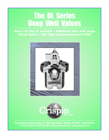
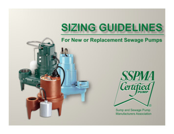
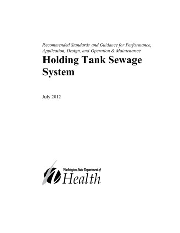
LESeries 401 SAVV4 0 0NITSEWAGE AIR/VACUUM NGATTACHMENTSOPTIONALCONCAVEFLOAT*LARGER SIZESHAVE FLANGEDINLETSINLETVALVEThe upper float shuts off instantaneouslyagainst the seat, due to the impact zone andlifting force of the much larger CONCAVEBOTTOM FLOAT*, as sewage media entersthe valve body.Once closed, and pressurized, theAir/Vacuum valve will not open to release air.It will open under negative pressure allowingair to re-enter and prevent vacuum fromforming in the line.Generation IIBLOWOFFVALVEAir/Vacuum Valves are needed to vent largevolumes of air when the sewage line is filledand allow air to re-enter when draining, toprevent vacuum or column separation occurring. Sewage Air/Vacuum Valves utilize twofloats, each connected to a common stemwhich is guided through a bushing.AIR VALVES401 and larger Model APCO SewageAir/Vacuum Valves are specifically designedfor operation on Sewage and Waste Media.SEWAGE AIR VALVESPATENTED1075
SEWAGE AIR/VACUUM VALVE (cont.)Series 401 SAVVSeries 401 SAVVSIZE HATTACHMENTS4012 NPT1 NPT161 4”20”7”41554022 NPT2 NPT19 4”23 2”19 2”851154033 NPT3 NPT193 4”233 4”91 2”851184044 NPT4 PLAIN30”351 4”12”1302004066 FLG.6 PLAIN32 2”36 2”16”1902904088 FLG.8 PLAIN36”40”18”31043041010 FLG.10 PLAIN41”45”20”60080041212 FLG.12 PLAIN47”53 2”25”75098041414 FLG.14 PLAIN511 2”571 � and larger flanged outlets available.SPECIFY APCO WITH CONFIDENCE - SEWAGE AIR/VACUUM VALVE SERIES 401 SAVVSewage Air/Vacuum Valves shall allow unrestricted venting or re-entry of air through it, during filling ordraining of the force main to prevent vacuum. The Sewage Air/Vacuum Valve shall incorporate (2)stainless steel floats directly connected by a stainless steel stem, to maintain an air gap between the bottomCONCAVE FLOAT and top shut-off float. The air gap shall retard waste solids from the fouling or clogging thetop shut-off float. The internal baffle shall be fitted with a guide bushings and act to protect the shut-off floatfrom direct air flow. The baffle shall retain the Buna-N seat in place, without distortion for tight shut-off.All internals shall be easily removed thru the top cover without removing the main valve from the line. Thecomplete valve shall withstand 500 psi test. OPTIONAL - Inlet and blow off valves, quick disconnect couplingsand minimum 5’ hose for flushing. (Engineer to specify).The valve inlet shall be (engineer to specify) and the outlet (engineer to specify).The valve manufacturer shall furnish professionally printed installation and maintenance instruction manualswith each valve.Materials of construction shall be certified the following A.S.T.M. specifications:Body, cover & baffleUpper FloatLower Float* CONCAVE PATENTEDStem, Guide BushingSeatExterior Paint1086Cast IronStainless SteelStainless SteelStainless SteelBuna-NUniversal Metal PrimerASTM A126 GR.BASTM A240ASTM A240 T304Series T300Nitrile RubberFDA Approved for Potable Water
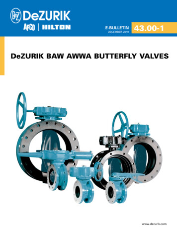
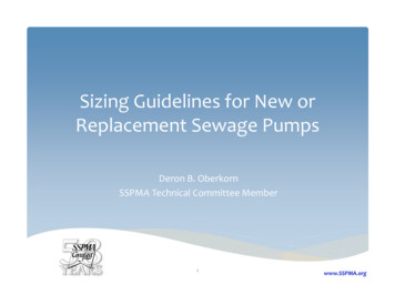
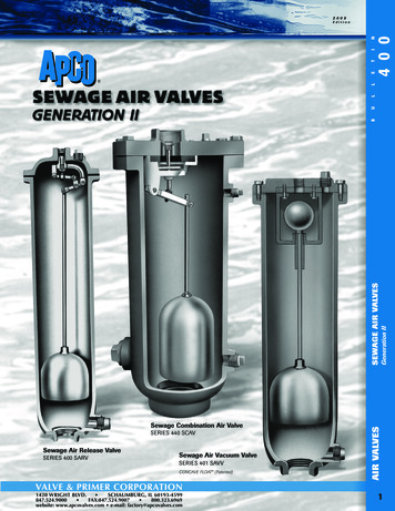
4 0 0TINAdditional gases given off by the sewage rise into the valvebody, displacing and lowering the sewage level until thefloat drops, opening the Venting Mechanism allowing gasesto escape. Sewage again rises to occupy the space vacatedby the escaped gas, lifts the float and closes the VentingMechanism. This cycle is repeated frequently as air and gascollect in the valve without spillage or spurting, due tothe sensitivity of the PATENTED CONCAVE FLOAT*.VENTINGMECHANISMCONCAVE FLOAT*PATENTEDBLOWOFFVALVESeries 400 and 450 SARV400450SIZE INCHESINLET2” NPT3” NPT4” NPT2” NPT3” NPT4” NPTOUTLETHEIGHTVALVEW/AMAJORDIAMETER 2NPT171 2231 271 21” NPT20261 291 IFICEDIAMETER*VENTINGCAPACITYCFFAM0 - 500 - 1500 - 3000 - 1500 - 3005/161/4 STD5/321/2 STD7/16559025350520WEIGHTPLAINW/A4155Generation IIHOW IT WORKS: When Sewage enters the valve, it rises,forcing air out ahead of it. Then as Sewage reaches theCONCAVE FLOAT*, it raises the float and float steminstantly, due to the very sensitive impact zone. This fastaction closes the Venting Mechanism, trapping the remaining air in the valve body. This entrapped air is initially atatmospheric pressure but it’s compressed after the VentingMechanism closes, and sewage continues rising in thevalve, until air and sewage are the same pressure. Thesewage then stops rising, leaving the Venting Mechanismfree from OPTIONALSEWAGE AIR VALVES400 and 450 APCO SEWAGE AIR RELEASE VALVES arespecially designed for use with Sewage and Waste media.The CONCAVE FLOAT* Stem and Body keep the valveVenting Mechanism as free from contact with the sewageas possible. The float hangs freely in the center of the valvebody and responds instantaneously to the fall and rise ofthe sewage media due to the CONCAVE FLOAT*.LLSeries 400 & 450 SARVESHUTOFFVALVESHOWN 90 OUT OFPOSITIONSEWAGE AIR RELEASE VALVE85 118*ORIFICE DIAMETER IS DETERMINED BY PRESSURE, NOT BY SIZE.AIR VALVESSPECIFY APCO WITH CONFIDENCE - SEWAGE AIR RELEASE VALVE MODEL 400 & 450 SARVSewage Air Release Valves shall have an elongated body and be designed to operate (open) while pressurized allowing entrained air in asewage force main line, sewage pump, or waste water system to escape through the air release orifice without SPILLAGE or SPURT. Afterentrained air escapes through the air release orifice, the valve orifice shall be closed by a needle mounted on a compound lever mechanism,(energized by a CONCAVE FLOAT*) and prevent media from escaping. The air release orifice will then remain closed until more air accumulates and the opening cycle repeats automatically. The internal compound lever mechanism shall be stainless steel to prevent corrosion.OPTIONAL: Inlet and blow off valves, quick disconnect couplings and minimum 5’ hose for flushing. (Engineer to specify).The internal linkage shall be fitted with a stem, having a stainless steel CONCAVE FLOAT* threaded onto the opposite end. The CONCAVEFLOAT* shall hang inside the valve body, slightly above the inlet 13” from the lever mechanism, thereby maintaining an air gap between themechanism and the waste media. The valve body and float shall withstand 500 psi shell test pressure. The valve inlet shall be 2”, 3”, 4”, N.P.T.Model 400 or 450. Engineer to specify.Materials of construction shall be certified the following A.S.T.M. specifications:
401 and larger Model APCO Sewage Air/Vacuum Valves are specifically designed for operation on Sewage and Waste Media. Air/Vacuum Valves are needed to vent large