Transcription
SCADA System FundamentalsCourse No: E01-007Credit: 1 PDHTracy Adams, P.E.Continuing Education and Development, Inc.22 Stonewall CourtWoodcliff Lake, NJ 07677P: (877) 322-5800info@cedengineering.com
SCADA System FundamentalsINTRODUCTIONJust as different countries have their own languages so do different technologies. The first stepto understanding a new technology is learning the unique language of that technology. Thiscourse is intended to provide you with an understanding of the terms and equipment associatedwith Supervisory Control and Data Acquisition (SCADA) systems.SCADA systems at their fundamental level are Industrial Control Systems. They are computerbased control systems that monitor and control industrial processes that exist in the physicalworld. SCADA systems can be found in manufacturing facilities, oil production and processing,pharmaceuticals, energy, water treatment and distribution, and the list goes on. They are the bestcontrol method for processes that have large amounts of data that need gathering and analyzing,or are spread over large distances, or require critical control in fast paced processes.SCADA SYSTEM SIGNALSThe very basic components of a SCADA system are these signals: DI – Discrete Input DO – Discrete OutputDiscrete signals (also called Digital signals) provide an ON or OFF input to a SCADA system.This is the same binary signal format used in computer processors.The next basic types of signals are: AI – Analog Input AO – Analog OutputAnalog signals are continuous. A change in signal value reflects change in the parameters beingmonitored. Examples of analog signals are temperature and pressure.The signals generated by the instruments being monitored by a SCADA system are voltage orcurrent based. Analog signals can be formatted as: 4-20 mA, 0-20 mA, 1-5VDC, 0-5VDC,-10VDC to 10VDC.Values (whether discrete or analog), when used in a SCADA system, they need to be seen byOperators to be of any use. Tracy A. Adams 2014
SCADA SYSTEM DATA GATHERINGThe Operator’s access into a SCADA system is by: OIT – Operator Interface Terminal or an HMI – Human Machine InterfaceOIT’s provide a local interface, typically in a remote location or into an isolated system like skidmounted equipment. Screens to display information have a simple layout since displays are notlarge; anywhere from 4 inches to 14 inches.HMI software is used at the Central Control location. Software is installed on computers withfaster processors and larger monitors so the screens display more information. They also makeuse of animation to emphasize critical data or focus operator attention to important areas of aprocess or annunciate an alarm.The work horse of the SCADA system that effectively grabs data from instruments, converts theinformation to a format a computer program can understand, and handles high speedcommunication is the: PLC – Programmable Logic ControllerThe Programmable Logic Controller (PLC) was invented in 1968 to support the automobileindustry by Bedford Associates’ engineer Dick Morley. The first PLC was called a MOdularDIgital CONtroller, aka MODICON.Over time variations of the PLC have developed. The two primary ones are: RTU – Remote Telemetry Unit PAC - Programmable Automation ControllerThe Remote Telemetry Unit (RTU) was developed to gather data and then transmit that data to aremotely located processor. A RTU has communication capabilities of a PC and the IOcapability of a PLC, as well as being industrial hardened. However, it does not control processesusing an internal program. It functions as a Data logger that can transmit data at a certain time toCentral or when polled. A hybrid version of the RTU contains a PLC that does control localprocesses and performs the communication functions of a RTU.A PAC is the next generation of a PLC. It has the same form and function as a PLC but itsprocessor is more related to a computer in its speed and computing methods. Its greatestadvantage is the communication function which allows it to work more effectively with moderncommunication networks that are Ethernet based. Tracy A. Adams 2014
SCADA SYSTEM TYPESData gathering and system control at the highest level is broken into two basic systems: SCADA – Supervisory Control and Data Acquisition DCS – Distributed Control SystemDefinition of SCADA is a Monitoring and/or Control System that utilizes a central computer forstoring information, and onsite/remote hardware to monitor facilities and processes. Control maybe automatic or manual and may occur at the remote units or the central computer.Definition of DCS is a Monitoring and/or Control System that utilizes a central computer forstoring information and onsite/remote hardware to monitor facilities and processes. Control maybe automatic or manual and may occur at the remote units or the central computer.While a SCADA system and a DCS system are essentially the same at all levels, there is a verybasic difference. A SCADA system is event driven and operator concentric. It is data gatheringorientated. Data is stored in database and control is usually remotely originated. Whereas, aDCS is process state driven. It is directly connected with field devices and control is donelocally and automatically. The operator is just informed of what has happened.A SCADA master station generally considers changes of state (both status points and analoguechanges leading to alarms) as the main criteria driving the data gathering and presentationsystem. Any undetected changes of state simply cannot be missed. A change of state will causethe system to generate all alarms, events, database updates and any special processing requiredrelating to that. Event lists and alarm lists are of major importance to the operator, sometimesmore so than data screens. S is for Supervisory - an Operator takes action.Conversely, DCS systems are process control systems that are state based and consider theprocess variable's present and past states to be the main criteria driving the DCS. PLC protocolsare generally register scanning based, with no specific change of state processing provided.Should a point toggle between scans, it will not be seen by the DCS. If any change of states arecritical (as some would be for a DCS used for SCADA applications), a point must be latched onuntil it is confirmed it has been scanned, which can be difficult and non-deterministic. DCSsoftware tasks are generally run sequentially, rather than event driven. If a process starts tomove from a set parameter, the DCS responds to maintain that parameter value. Notifying theOperator is a secondary consideration. Events and alarm lists are secondary in importance to theprocess displays, and filtering may not be as complex and flexible. On the up side, thegeneration and display of data, especially analogue trends and standard process blocks, is farmore user friendly and easier for both operators and engineers. Tracy A. Adams 2014
SCADA systems historically have been broken down into two basic flavors:Proprietary SCADA System: All or most components manufactured by one supplier Installation and service from same single source Lack of compatibility with other products Uses proprietary communications and programmingMix & Match SCADA System Usually supplied by System Integrator Usually uses open communication protocols Uses off-the-shelf products PLC’s program using standard procedures Utilizes open HMI SoftwareOriginal SCADA systems were proprietary. The Manufacturer built all the hardware, software,installed the equipment and did all the programming.As computer technology improved, SCADA systems evolved to take advantage of theadvancement. Hardware components started coming off the shelf. SCADA software started tobe developed to use open protocol communication standards. This led to the rise of SystemIntegrators, companies that developed custom systems to meet the needs of the end users.SCADA SYSTEM COMPONENTSThese are the four basic parts of a SCADA system. Field Instruments PLC/Remote Terminal Unit Communications Link – open standard (like MODBUS) and proprietary Central Computer Station including HMI Software – Proprietary for specific RTUs oropen including interfacing many products Tracy A. Adams 2014
We are going to look at each of these parts and identify the basic components for each:A. FIELD INSTRUMENTSDiscrete signals are generated by:a. Limit switchesb. Pushbuttonsc. Float switches Tracy A. Adams 2014
d. Flow switchese. Relay contactsf. Selector switches Tracy A. Adams 2014
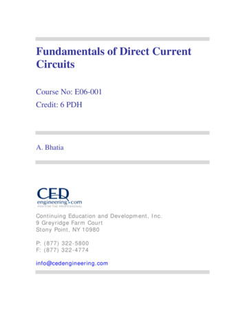
Discrete signals have three basic configurations that are used:Form A - Normally OpenForm B - Normally ClosedForm C - Normally Open-Normally Closed combinedAnalog signals generally come from instruments and motion controlling equipment. The mostcommon instrument is the analyzer. Analyzers are test equipment located in the field formonitoring the quality of a process. Analyzer primary signal output is analog but there aretypically some discrete contacts for alarms. Below are some examples of analyzers: Tracy A. Adams 2014
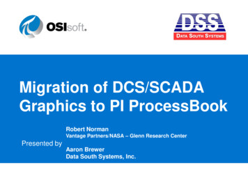
This is a turbidity meter used to measure solids in water.Below is a Chlorine Analyzer used to measure the level of chlorine in water leaving a treatmentplant to ensure it is safe for humans. Tracy A. Adams 2014
While not an instrument, a Variable Frequency Drive (VFD) is a field device that frequentlyinterfaces with SCADA systems to control process outputs. VFD’s are used to power motorsdriving pumps and fans. VFD’s generate analog and discrete signals.Typical signals from a VFD are: Speed Indication (Analog) Speed Control (Analog) Running (Discrete) Fault (Discrete) Start Command (Discrete) Tracy A. Adams 2014
B. PLC/RTUPLC’s come in a wide variety of sizes and shapes. They are used from controlling nuclear powerplants to controlling a sump pump in a parking garage.High end PLC’s can handle multiple racks of IO modules, various communication modules, andmay be installed in a redundant configuration so the loss of a power supply or processor will notstop control of a facility.The latest step in the evolution of PLC’s is the Programmable Automation Controller (PAC).A PAC has a computer processor so it works better with Ethernet networks (routers/switches)which are becoming prevalent in SCADA systems. Programming can also be done in more mainstream programs (C , etc) Tracy A. Adams 2014
Smaller PLC’s are configured for just a few points. Sometimes they may only have discretesignals, and function as intelligent relays. They are not typically expandable to add more IOpoints.Programming is usually simple. Sometimes the programming can even be done with the keys onthe front of the PLC. Relay Ladder Logic was the first programming language for PLC’s. Itmimicked the wiring diagrams electricians were used to seeing in control panels in software. Infact, electricians were the first PLC programmers.As hardware and software changed, the companies making the products started diverging. Itbecame apparent that standards had to be developed so the software and hardware could worktogether. There also started to be programmers who were familiar with multiple high levelprogramming languages and never saw the inside of a control panel. In Europe IEC developedstandard 61131 which specified five styles of programming to be used in PLC’s: Relay Ladder Logic Function Block Diagram Structure Text Instruction List Sequential Function Chart Tracy A. Adams 2014
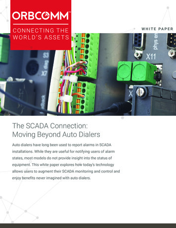
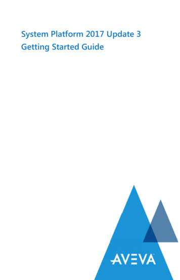
In addition to these standards, PLC’s can have specialty modules installed that use C or Basicfor special program requirements.PLC’s cannot be mounted to a wall and left unprotected. They are mounted in enclosures thatprotect them from hostile environments. A typical PLC panel is shown below with high endPLC’s configured with redundant processors and power supplies. Tracy A. Adams 2014
Shown below is an RTU configured with a PAC that can provide local control in casecommunications are lost. This panel communicates via leased line using the modem in the lowerleft corner of the panel.This is an example of a control panel that shows the customized approach taken to buildingcontrol panels. This is designed for a site with a large number of physical IO. A radio will be Tracy A. Adams 2014
installed in the upper right hand corner for communication. Note the batteries in the lower rightcorner for backup power. A Remote IO panel (an RTU) interfaces with field devices but has noprocessors for local control. It is equipped with a communication module instead.This style reflects the original design on RTU’s. It has a processor to handle communicationsvia the radio mounted on the door. It receives signals from field devices which it passes throughto Central for display by the SCADA HMI. It then passes any commands from Central to thefield devices.Autodialers (shown below) are a very basic form of RTU. This device receives site alarms asDigital Input signals. It then calls a Duty Operator over a standard telephone line (POTS) or acell phone. The Operator can acknowledge the alarm using the telephone keyboard. Higher endAutodialers also allow the Operator to do basic controls via the keyboard such as starting abackup pump or operate valves. Tracy A. Adams 2014
C. CommunicationRadios are the most common communication method in large SCADA systems. Licensed radioswere originally used. Then in 1987 the FCC marked a radio frequency band segment forIndustrial Scientific Medical (ISM) use. This was an unlicensed segment that was opened foruse and did not require a license. The ISM is in the low 900MHz range.The ISM band is limited to a maximum of 1 Watt transmitting power. This was the methodselected to reduce interference by limiting the range of the transmissions. Licensed radios arestill used in SCADA systems for operators who have a long distance that needs to be coveredbetween sites.Characteristics of most frequently used frequencies are:1) Licensed VHF – 132-174 Mhz, 400Mhz Up to 5 Watts Power Very Good Signal Transmission2) Licensed UHF – 380-512 Mhz Good Signal Transmission3) Unlicensed Spread Spectrum – 900 Mhz 1 Watt max. Power Line-of-Sight, weather dependent Ethernet protocol versions are available in all frequencies.A recent trend in SCADA system has been the incorporation of video cameras and still camerasto provide Operators real time images of what is happening at remote sites. The need forincreased security was the driving force behind this trend.Images contain a lot of data. In order to transmit images over a radio link and make thempractical, frequencies in the 2.4 GHz and 5.8 GHz are used. Tracy A. Adams 2014
Above is the basic radio form that was originally selected for industrial use and is still a verypopular and functional form used today.As electronics improved, radios became smaller while still keeping the same performancecapabilities. This style of radio is designed to be mounted on DIN rail. Tracy A. Adams 2014
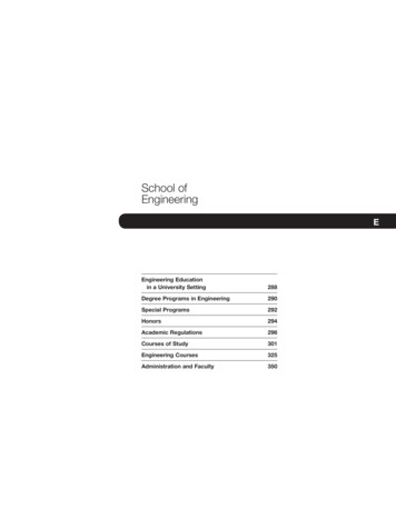
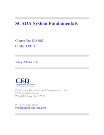
One of the areas that a radio link loses transmission power is the cable connecting the radio withthe antenna. The above radio is a weatherized unit that can be mounted on the mast just belowthe antenna. This eliminates signal power lost during transmission through the antenna cable.Typically an Ethernet connection is provided to interface with PLC’s or computers.The two basic workhorse antennas of SCADA systems are YAGI and Omni.YAGI Tracy A. Adams 2014OMNI
The yagi is for directional transmission and the omni provides 360 degrees of transmission.An omni antenna will be used at a SCADA Central site to broadcast to RTU’s at many differentlocations. The yagi antenna transmits radio signals in the direction the antenna is pointing.As higher radio frequencies (2.4 GHz and 5.8 GHz) have come into use for transmitting moredata (e.g. video signals), panel and parabolic antennas are now common in SCADA Systems.Another application using radios is wireless IO. This is a paired set of radios that have terminalsfor connecting physical IO signals (discrete or analog). One radio is for connecting fielddevices: a pressure transmitter or a high level float. The second radio receives the signals withthe field devices values and retransmits the signals over wires connected to a PLC.The two radios are paired to work together. They cannot communicate to any other radios. Thissystem eliminates all the conduits and wires that would have been installed to connect the fielddevices to the PLC. No special communication configuration had to be designed to allow theradio to talk to the PLC. This is a way to save money when needing to pick up a single point andtie it into a SCADA system. Tracy A. Adams 2014
Within SCADA systems multiple protocols are available for communication. Protocols are themethodology used to encapsulate data for transmission between SCADA components. Designersjust need to select the method best suited for the system.Originally serial communications were conducted over special cables with various protocols(Fieldbus, ControlNET, Modbus RTU, etc). These were the standards for many years and theyare still used frequently.The late comer Ethernet has recently made big move into the field. As the electronics becameindustrialized, the ability to use the same communication in a SCADA system (that the ITDepartment was familiar with) became a money saver.It also streamlined the interface between PLC and SCADA computers. It has simplified SCADAcommunications by allowing the gathering of data from “smart” devices such as VFD’s, powermonitors, analyzers, etc. with just a single cable.In addition to the traditional radio and serial cable communications, SCADA systems also use: Cellular – PCS, CDPD Telephone Lines – Dedicated leased and Dial-up Wireless Internet DSL Broadband Fiber Optic – supports Ethernet protocol Satellite – Geosynchronous LEO Tracy A. Adams 2014
Designers just need to find the right method to solve the communication problem. For example,satellites are used for accessing remote sites in mountainous terrain where it is impossible to geta radio signal out or run a cable.D. Central ComputersOne of the first steps in designing a SCADA system is to determine which CommunicationProtocol will be used. The most common protocols used are: MODBUS RTU or MODBUS ASCII (original protocol used) DEVICENET CONTROLNET Profibus Foundation Fieldbus DH , DF1 DNP3 Ethernet (MODBUS TCP, ETHERNET IP)Protocols are the languages that the equipment uses to communicate. Just as people speakEnglish, French, German, etc., so have different protocols been developed by differentmanufacturers. These different protocols are intended to maximize the hardware benefits of theirequipment. Some of these protocols are open for anyone to use and some are proprietary.The second step is determining the hardware: Computer Hardware inc. UPS – Off-the-shelf Central RTU – Sometimes for polling Communication Interface – Radio/Antenna, Telephone Modem, DSL Modem HMI – Human Machine Interface Common HMIs – Intellution, Wonderware, Citec, Trihedral Engineering VT-Scada Internet Based – Mission Web based - Inductive Automation Tracy A. Adams 2014
At the high level end of a SCADA system, you see the equipment and software that theOperators use to interface with the system. At this level communication is the key process.There is the hardware and software to interface with all the field components.Also, there is hardware and software to interface with the operators. This side of the process isvery graphic oriented. SCADA Fundamentals Alarm Annunciation Remote Control Trending – Real Time/Historical Data Logging / History Alarming Reporting Security High Level Optimization Strategies Auto-Dialer / Pager Remote MonitoringThe SCADA HMI software is written to provide these services to the Operators for their day today operations: SCADA Fundamentals Analog Summary Radio Error Analysis Log Report – All Data Detail Report Pump Activity – Total & Ave Run Times, Starts Pump Discrepancy – Excessive changes Tracy A. Adams 2014
Flow Water QualityAnother very important feature of SCADA HMI software is documentation for historicalpurposes. The data collected is achieved and then distributed in various formats. Thisinformation helps with maintenance as well as reporting to supervisory organizations.A typical graphics screen allows the operator in a quick glance to see the status of all the criticalequipment and processes in an area. Tracy A. Adams 2014
Trending is data spread over a period of time and presented in a graph. This is a useful tool forimproving processes.CONCLUSIONSCADA systems are a vital tool for keeping our society going. As electronics andcommunications have improved, so have the capabilities of SCADA systems. SCADA systemsmake controlling large and small processes easier for Operators whether they are intelecommunications, water treatment, manufacturing, energy production, oil production,transportation, etc. Tracy A. Adams 2014
Programming is usually simple. Sometimes the programming can even be done with the keys on the front of the PLC. Relay Ladder Logic was the first programming language for PLC's. It mimicked the wiring diagrams electricians were used to seeing in control panels in software. In fact, electricians were the first PLC programmers.