Transcription
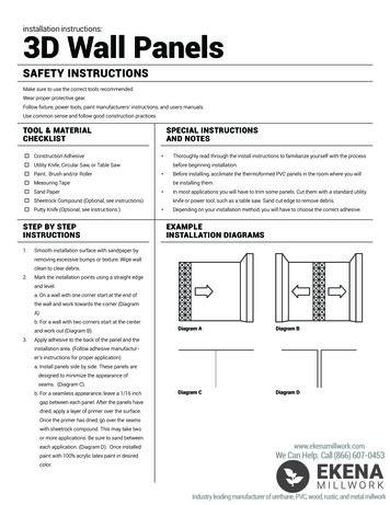
INSTALLATION INSTRUCTIONSMODELS 600HS, 1200HS, 2000HSPLUS “VCU WIRED REMOTE”600HS “S” Housing600HS “L” Housing1200/2000HS “S” Housing1200/2000HS “L” Housing
ASSEMBLY INSTRUCTIONS VCUWIRED REMOTE VERSIONSTEP 1.STEP 2.STEP 3.Unpack your unit and remove all packing from the blower and motorassembly.Remove both housing access doors.VERY IMPORTANT NOTE! MAKE SURE THE BLOWER WHEEL SPINSFREELY.For 1200/2000 "S" version units skip to Step 8.STEP 4.From the filter section, remove the wire framed pre-filter and carbon filter.STEP 5.Locate the two HEPA filter holding strips that also act as a tray for thecarbon filter and pre-filter. Remove the two hex nuts and associated screwson both holding trays and remove the trays from the housing.STEP 6.Remove the hex head screws that are in the gasket material on theBOTTOM (motor) section of your unit. The BOTTOM & TOP (filter)sections are symmetrical, so they can be rotated 360 degrees so thedischarge can be pointed in four different directions to accommodateany installation configuration. This allows for best directional locationfor the TOP section filter access door. MAKE SURE THE DISCHARGEDIRECTION IS CORRECT FOR YOUR APPLICATION BEFOREASSEMBLING. Align the sections as desired. Place the TOP section onthe BOTTOM section, align the holes and tighten the hex head screws.STEP 7.Insert HEPA filter. BE CAREFUL TO NOT PUNCTURE THE HEPA MEDIA.The gasket should be toward the motor unit. Center the gasket over theknife-edges so that it is even on all four sides. Replace the two HEPAholding trays.STEP 8.Remove the wrapping from the carbon filter and slide the carbon filter andpre-filter back into the trays and replace the access door.IF YOU ARE USING YOUR SYSTEM AS A STAND ALONE, YOU MAYSKIP TO ELECTRICAL WIRING SECTION.Please look at the attached "typical installation" drawings. The inlet duct should beconnected to the main return air duct leading to the heating/cooling system, and thedischarge duct should be connected to the point where the return air duct enters theheating/cooling fan area.ALWAYS INSTALL THIS SYSTEM IN A BY-PASS CONFIGURATION.
MATERIALS NEEDED FOR COMMON HVAC INSTALLATIONS1.)Section of 12" (14" for 1200/2000 units) diameter sheet metal (recommended) orflex duct. You will need 3' to 6' for most installations.2.)Section of 10" (14" for 1200/2000 units) diameter sheet metal (recommended) orflex duct. You will need 6" to 24" for most installations.3.)12" collar (14" for 1200/2000 units) for connection to return air duct.4.)10" collar (14" for 1200/2000 units) for connection to fan return side of HVAC unit.5.)4" by 18" ( 4" by 24" for 1200/2000 units) piece of sheet metal for Air Scoop. Or aprefabricated damper. This is recommended to be installed with every unit.6.)Sheet metal screws, duct tape or metal tape. 12 gauge electrical wire for power tounit.7.)Thermostat wire.INSTALLATION OF THE DUCTINGSelect the proper location for the attachment of the inlet and discharge ducts. Try tokeep a minimum of 6 feet between the inlet and discharge openings. This will preventthe Pure Air Systems’ filtration unit from recycling the same air. Cut the openings in theexisting return air duct. We recommend an air scoop be placed inside of the return airduct so that it directs air into the inlet duct of your filtration system. You can use adamper as an air scoop. Make sure the damper is angled to direct the air from the returnair duct into the inlet duct of your filtration system.Use sheet metal screws, duct tape or aluminum tape to attach the duct sections to thecollars on the inlet of the unit and the air return. Make sure there are no airleaks. Repeat this same procedure for the discharge duct. Make sure allconnections are tight and taped.ELECTRICAL WIRING & POWER CONNECTION***WIRING FROM 240 VOLT***For 240 volt operation you will need to cut the "black jumper wire" that connects pin1 to pin 2 on the 5 pin white power connector attached to the back end of the motor.You will also need to insure the transformer is a 240V to 24V and 10VA.FAILURE TO COMPLETE THIS WIRING CHANGEWILL RESULT IN DAMAGE TO THE MOTOR.
NOTE: ALWAYS FOLLOW ELECTRICAL CODES FOR YOUR AREA. We recommend adedicated 15 amp service for all of our air filtration systems. The conduit connector isdesigned for EMT conduit or Romex cable. Wire the black, white and green (ground)wires through the conduit connector to the black, white and green wires inside the unit.VCU CONTROLLERThe VCU digital speed controller will allow you to adjust the speed from 0 -100% in1% increments. The LED display will show the speed in percent of air volumecapacity. If no other changes are made to the VCU controller after 20 seconds thecontroller will blink with the speed shown and then switch to 0 if you are not usingthe RPM feature. If you using RPM feature the LED display will blink after 20seconds from speed to RPM. Always turn the power off at the lighted rocker on/offswitch when the unit is not in use. Turning the VCU controller to 0 will stop themotor but will not turn off the power to the motor.WIRED REMOTEThe VCU controller can be located in any location of your choosing within 150 feet of the unit.Run low voltage, six wire, thermostat wire from the unit to where you are going to mount theVCU controller. Then simply match up the wires to the terminal strip located in the unit withthe terminal strip located with the VCU controllerTESTING THE UNITTo insure that the VCU controller is wired correctly, check that the controller isilluminated. Turn on the lighted rocker switch on the unit. The VCU controller shouldnow be capable of adjusting the speed of the motor in the unit. If it does not, pleasecheck that the wiring between the terminal strips is correct.ODOR ADSORPTION MODELSAll Odor Adsorption models are identical to the regular models except there is no HEPAfilter. In-lieu of the HEPA filter there is a carbon cannister.
WIRED REMOTE The VCU controller can be located in any location of your choosing within 150 feet of the unit. Run low voltage, six wire, thermostat wire from the unit to where you are going to mount the VCU controller. Then simply match up the wires to the terminal strip located in the unit with the terminal strip located with the VCU controller