Transcription
6.0 Analysis 2: Chilled Beams Cost & Schedule Impact (Mechanical Breadth)6.1 BackgroundThe mechanical package for the JHH project accounts for 29.1% of the construction cost. The HVACsystem alone totals 79,444,970 or 13.9% of the construction cost. The critical path of the project largelyinvolves the installation of the HVAC system.The JHH campus has a central utility plant that is capable of supplying the NCB with chilled water andhigh pressure steam. Therefore, the new facility does not include any boilers or chillers. The currentHVAC system is a variable air volume (VAV) with reheat coils in each VAV box. On average each VAV boxserves 3 rooms that are on one zone. There are 19 air handling units with sizes ranging from 11,000 –133,000 CFM. They are primarily located on the 6th and 7th floor.When designing a HVAC system for a healthcare facility, the engineer must consider infection control,filtration requirements, outdoor air requirements, recirculated air requirements, air change rates, etc.Hospitals have much stricter design criteria than typical buildings. A VAV system is the most commonsystem used in invasive areas of healthcare facilities. However, non‐invasive areas such as office space,waiting rooms, cafeterias, patient rooms, etc. do not have as strict of guidelines. For this reason, theseareas have the potential to use a different HVAC system, such as chilled beams that could potentially savetime and money.6.2 Problem StatementAnalysis 1 showed that the top two goals for the owner, A/E, and contractor are to deliver the projecton/under budget and on time.Currently, the 1st package of changes (CCD 1‐38) has been evaluated by Clark/Banks and they havedetermined that the schedule will need to be extended 7 months. This is because the HVAC system wasseverely impacted by the changes. The cost of accelerating the schedule from 7 months to 3 months delayby working 300 mechanical craftsmen overtime is 2 million. This has caused JHH to not meet their toptwo goals.6.3 GoalThe goal of this analysis is to demonstrate that chilled beam HVAC systems in non‐invasive spaces havethe potential to lower the cost (initial and life‐cycle) and accelerate the construction schedule.6.4 ResourcesTROX USA – Ken LoudermilkTROX USA – Chris LawrenceDADANCO – Bill RaffertyPierce Associates, Inc. – Dan DonaghyClark Construction – Jim SalvinoWeiger – Final Report45 P a g e
Poole & Kent – Donald CampbellUnited Sheet Metal – Mike TopperJohns Hopkins Facility Group – Bob SingerBR A – Mark OcteauSmithGroup – David VarnerPenn State – Moses Ling6.5 AnalysisChilled Beam System BackgroundAn emerging technology from Europe is the chilled beam HVAC system. They have been successfullyusing chilled beam systems in healthcare facilities for the past 20 years (see Table 4 below for sampleprojects). Within the past few years, several projects have popped up in the USA with these systems suchas Constitution Center in Washington D.C. and the Yale Hospital Expansion project in New Haven, CT.Table 4: Healthcare Projects in Europe Using Chilled Beams (Source: Frenger Systems)HospitalHealthcare Trust# of Chilled BeamsYearConsultingEngineerRoyal Sussex,BrightonUCLH LondonBrighton & SussexUniversity HospitalsUniversity CollegeLondon HospitalsGreater GlasgowHealth BoardNations HealthcareGreater GlasgowHealth BoardMid YorkshireHospitalsThe London4502003Whichloe TB&ADSSR3502008Buro Happold4,5002008‐2013TB&A and DSSRBeatson OncologyQMC NottinghamACAD Hospitals,ScotlandWakefieldHospitalsBarts & RoyalLondonWeiger – Final Report46 P a g e
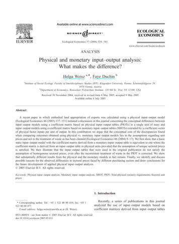
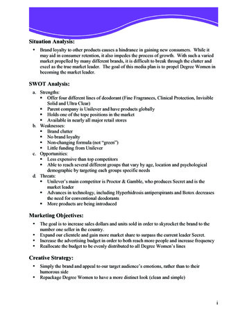
Chilled beam units have finned chilled water heat exchanger cooling coils, capable of providing 1,000BTU/hr of sensible cooling per foot of beam. They take advantage of the fact that water can move energymore efficiently than air. Figure 14 below shows that a 1” diameter water pipe can carry the same coolingcapacity as an 18” x 18” air duct. Thus, chilled beams can dramatically reduce AHU and duct sizes.Figure 14: Cooling Energy Transport Economies of Air and WaterThere are two main types of chilled beams – active and passive. Passive chilled beams use finned tubeheat exchanger coil to provide convective cooling to the space. They do not use fans, ductwork, or anyother component. Since they do not have a source of providing primary air to the space, another source ofair is required for ventilation and humidity control.Active chilled beams use a ducted primary air (conditioned) supply to induce room air across the coolingcoil where it mixes with the primary air and discharges in the space. The chilled beam provides most ofthe sensible load while the primary air provides the ventilation and latent cooling. A Hygienic ActiveChilled Beam is the recommended solution for this project (see Appendix A for product data sheets).Figure 15 below shows a cross section through an active chilled beam. (1) Primary air is fed from acentral AHU through a series of nozzles (2). The primary air creates an induction of room air (3) thatpasses through a cooling coil (4). The primary air and room air are then mixed and discharged to thespace (5).Figure 15: Active Chilled Beam Cross SectionWeiger – Final Report47 P a g e
Chilled beams have many advantages including low energy consumption, space savings, improvedcomfort, no regular maintenance, and easy commissioning. The design intent of chilled beams is to sizethe primary air to meet ventilation or latent load requirements and use the beams to provide the rest ofthe sensible cooling load. It is common to see 75‐85% reduction in circulated air when using chilledbeams compared to all air systems according to DADANCO. This reduction in air can reduce theductwork, fans, AHUs, etc. by the same proportioned amount. The downsizing of fans and AHUs results inless energy consumption because it is much more energy efficient to move water instead of air. This cansave significantly on the life‐cycle cost of a building.By reducing the ductwork by 75‐85% it frees up space in the ceiling plenum. Therefore, the floor‐floorheight can be reduced. This can save money on structure and the façade. Another advantage could be inareas with height restrictions such as Washington, D.C. where it may be possible to add another floor. Italso lends itself nicely to renovation projects where the ceiling plenum is restricted.The room comfort is maintained by providing excellent air movement with uniform air temperatures (seeFigure 16 and 17 below). This reduces unwanted drafts and hot spaces in the room. Full ventilation airrequirements are delivered to the spaces at all times and loads. Humidity control is met as the constantvolume primary air is delivered with the proper moisture content to satisfy the latent loads.Figure 16: Air Movement Throughout the Room(Source: DADANCO)Weiger – Final ReportFigure 17: Uniform Temperature Throughout the Room(Source: DADANCO)48 P a g e
Chilled beams do not have any moving parts which reduces the maintenance costs. In the recommendedHygiene Chilled Beam for this project, there is an inbuilt filter which will capture all the airborne bacteriaas the air is recirculated. This will need to be replaced every 6 months which is the same as the currentVAV system. Figure 18 below shows maintenance personnel cleaning a chilled beam.Figure 18: Maintenance Personnel Cleaning a Chilled BeamThe commissioning process is much easier than VAV systems. Chilled beams only require adjustments tothe water balancing valves and primary air balancing dampers through static pressure readings. Theadjustments can be made by turning regulating screws with an allen key with the underplate in position(see Figure 19 below).Figure 19: Adjustment for Regulating Air Amount and SpeedWeiger – Final Report49 P a g e
Sizing the Chilled Beam SystemFor this analysis, the current VAV system design will be left untouched for the invasive spaces (i.e.operating rooms, trauma rooms, triage, exam rooms, etc.). The remaining non‐invasive spaces will beanalyzed to determine the cost and schedule impact of using chilled beams.The sheer size and complexity of the HVAC system makes it virtually impossible to analyze each aspect ofthe HVAC system for this thesis. Therefore, representative and typical spaces will be analyzed and theirresults will be extrapolated to the rest of the spaces in question.The two main spaces that are representative of the non‐invasive spaces are the office and patient rooms.These areas make up the majority of the non‐invasive spaces. They also represent the two extremes ofthe design criteria for the non‐invasive spaces. The office spaces have the least amount of designrestrictions while the patient rooms have the most. Analyzing these two spaces will provide a workingaverage that can be used to analyze the entire impact.Office SpaceLevel 6 was analyzed as the typical floor for the office spaces. The entire floor functions as faculty offices,meeting rooms, lounges, and filing rooms. Each VAV box serves a certain zone that ranges from 1‐ 9rooms. The following assumptions were used for the calculation. The supply CFM shown on the drawings for each corresponding VAV box represents the designloads for that zone.Each room that is a part of the zone has similar loads.By examining the entire floor, including the north, south, east, west and inside rooms providerepresentative load conditions.The number of seats or area to a room was used to estimate the number of people that wouldoccupy the room at maximum load.Sizing is based on cooling load, not heating loado Heating will only be required on perimeter spaces and can be accomplished by addingheating coils in the beams.The following calculation is an example of how the chilled beams and primary air supply were sized.VAV Box S6D‐1 Total Supply for this VAV 300 CFM6 people are expected to occupy the zone at maximum capacity1 room is served by this VAVRoom temperature design 70 FSupply primary air temperature 55 F1. Total Sensible Design Load 1.08 x Total Supply CFM x (Room Temp – Supply Temp) 1.08 x 300 CFM x (70 F ‐ 55 F) 4,860 BTU/hrWeiger – Final Report50 P a g e
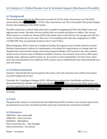
2. Ventilation air required per ASHRAE 62.1 – 2007 is 25 CFM/person for patient rooms (see Figure 20below). Office spaces are not shown. To be on the conservative side, 25 CFM/personwill be used for both the office and patient rooms.Figure 20: ASHRAE 62.1 – 2007 Ventilation Air Requirements for Healthcare Facilities3. Ventilation Air Required 25 CFM/person x 6 persons 150 CFM4. Assume that ventilation air governs primary air supply right now and then check to see if it is greaterthan the latent load air requirement later.5. Sensible Cooling Capacity of Primary Air 1.08 x Vent. Air CFM x (Room Temp – Supply Temp) 1.08 x 150 CFM x (70 F ‐ 55 F) 2,430 BTU/hr6. Sensible Cooling by Chilled Beam Total Sensible Load – Sensible Capacity of Primary Air 4,860 BTU/hr – 2,430 BTU/hr 2,430 BTU/hr7. Latent load in the room can be approximated by the general rule of thumb that each person gives off200 BTU/hr of latent load.8. Latent Load 200 BTU/hr/person x 6 person 1,200 BTU/hr9. Latent Cooling Capacity of Primary Air 4,840 x Vent. Air CFM x (WRoom – WPrimary) 4,840 x 150 CFM (0.009 – 0.007) 1,452 BTU/hr10. The latent cooling capacity of primary air is greater than the latent load. Therefore, the ventilation airis adequate in supporting the latent load for the zone.11. On average, a chilled beam can produce 1,000 BTU/hr/ft of sensible cooling capacity.12. Chilled Beam Size 2,430 BTU/hr 1,000 BTU/hr/ft 2.43 ft Chilled Beam 3 ft Chilled BeamWeiger – Final Report51 P a g e
13. Primary Air Reduction 1 – (Primary Air CFM Total Current Supply CFM) 1 – (150 CFM 300 CFM) 50%Table 4 on the following page shows all of the calculations for the typical office rooms. Below is asummary of the findings: Percent Reduction in Primary Air 79%Average Chilled Beam Size per Room 5 ftTotal Cost of VAVs for Typical Area 15,078 0.61/SFTotal Cost of Chilled Beams for Typical Area 102,760 4.16/SFPercent Increase of Chilled Beams over VAV Boxes 682%Weiger – Final Report52 P a g e
Table 5: Chilled Beam Load Calculations for Office SpaceWeiger – Final Report53 P a g e
Patient RoomsLevel 8 was analyzed as the typical floor for patient rooms. The entire floor functions as patient roomsand nursing stations. Each VAV box serves a certain zone that ranges from 1‐ 5 rooms. The followingassumptions were used for the calculation. The supply CFM shown on the drawings for each corresponding VAV box represents the designloads for that zone.Each room that is a part of the zone has similar loads.By examining the entire floor (including the north, south, east, west and inside rooms) it willprovide representative load conditions.The number of seats or area to a room was used to estimate the number of people that wouldoccupy the room at maximum load.Sizing is based on cooling load, not heating loado Heating will only be required on perimeter spaces and can be accomplished by addingheating coils in the beams.The following calculation is an example of how the chilled beams and primary air supply were sized.VAV Box S8C‐33 Total Supply for this VAV 900 CFM12 people are expected to occupy the zone at maximum capacity4 rooms are served by this VAVRoom temperature design 70 FSupply primary air temperature 55 F1. Total Sensible Design Load 1.08 x Total Supply CFM x (Room Temp – Supply Temp) 1.08 x 900 CFM x (70 F ‐ 55 F) 14,580 BTU/hr2. Ventilation air required per ASHRAE 62.1 – 2007 is 25 CFM/person for patient rooms.3. Ventilation Air Required 25 CFM/person x 12 persons 300 CFM4. Assume that ventilation air governs primary air supply right now and then check to see if it is greaterthan the latent load air requirement later.5. Sensible Cooling Capacity of Primary Air 1.08 x Vent. Air CFM x
6.0 Analysis 2: Chilled Beams Cost & Schedule Impact (Mechanical Breadth) 6.1 . TROX USA – Chris Lawrence DADANCO – Bill Rafferty Pierce Associates, Inc. – Dan Donaghy Clark Construction – Jim Salvino Weiger – Final Report 46 Page Poole & Kent – Donald Campbell United Sheet Metal – Mike Topper Johns Hopkins Facility Group – Bob Singer BR A – Mark Octeau SmithGroup .