Transcription
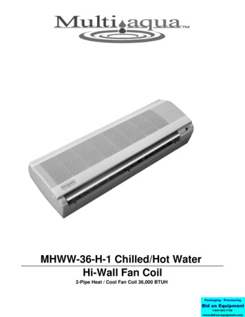
MHWW-36-H-1 Chilled/Hot WaterHi-Wall Fan Coil2-Pipe Heat / Cool Fan Coil 36,000 BTUH
MHWW NOMENCLATURE BREAKDOWN2-Pipe Heat/Cool Hi-Wall Fan CoilMHWW-36 - H-1Voltage1 208/230/-1-50/602-Pipe Heat/CoolHeat/CoolNominal BTUH36 36,000Available Model NumbersMHWW-36-H-1
HVAC Guide SpecificationsChilled and Hot Water Hi-Wall Fan Coil2-PipeNominal Size:36,000 BTUHMultiaqua Model Number:MHWW-36-H-1Part 1-General1.01 System DescriptionMultiaqua Chilled Water Fan Coils are manufactured with high impact molded polymers.1.02 Quality AssuranceA. Certified in accordance with U.L. Standard 95, latest version (U.S.A.)B. Manufactured in a facility registered to ISO 9002, Manufacturing Quality Standard.C. Fully load tested at the factory.D. Damage resistant packaging.1.03 Delivery, Storage and HandlingA. Packaged and readied for shipment from the factory.B. Controls shall be capable of withstanding 150 F storage temperatures in the control compartment.C. Stored and handled per manufacturer’s recommendations.Part 2-Product2.01 EquipmentA. General:1. Unit shall be a factory assembled and tested chilled and hot water fan coil.2. Shall be assembled with high quality.3. Contained with the unit shall be all factory wiring, piping, associated controls and specialaccessories required prior to start up.B. Unit Cabinet:1. Composed of high impact polymers.2. Shall be internally insulated to insure quiet operation.C. Fan Motors:1. Shall be available in 208/230-1-50/60 vac.1. Fan motors shall be three speed, direct drive, and PSC type.2. Totally enclosed.3. Internal overload protected.4. Unit shall contain a swing motor to modulate the discharge air.D. Blower Wheels:1. Blower wheels are tangential and dynamically balanced.E. Water Coil:1. Manufactured with water coils containing 3/8” copper tubing mechanically bonded to aluminumfins.2. Coils shall be factory tested to 350 psig.F. Drain Pan:1. All drain pans shall be molded with high impact polymers.2. The exterior of all drain pans shall be insulated with closed cell to prevent condensation.3. Pans shall contain a flexible drain tubing that is accessible from the back of the unit.G. Filters:1. Unit shall contain 65% washable filters.
Part 3-Controls and Safeties3.01 ControlsA. Fan coils shall be completely factory wired and tested.B. Controls shall include a circuit board, room sensor, indoor coil thermistor, transformer and wirelessremote.C. Controls are capable of incorporating an optional Multiaqua hard-wired thermostat.D. Controls shall be capable of controlling the 2-pipe fan coil on a 4-pipe hydronic system. Contact factoryfor piping and wiring layouts.3.02 Safeties:A. Fan coil shall contain a non reusable fuse on the secondary voltage side of the transformer.B. Discharge air sensor.Part 4-Operating Characteristics:4.01 Electrical RequirementsA. Unit shall incorporate a three prong male primary electrical power cord.B. Electrical power supply shall be rated to withstand 120 F operating ambient temperatures.
MHWW-36-H-1 Product SpecificationsPhysical DataModel NumberHeight(in)Length 6-H-114.2556.508.3750.503-183/83/43/43/4Electrical DataModel NumberMHWW-36-H-01HiSpeedCFM850Volts/ Phase/Hertz208/230-1-50/60MotorHP1/12Full LoadAmpacity0.42These specifications are subject to change without notice.Fuse or HACRCircuit BreakerPer CircuitMinimumAmpsMaximumAmps.531
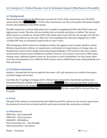
MHWW-36-H-1 Chilled Water Performance DataMHWW-36 COOLING CAPACITIESCFMEWT( F)GPM7.28.0850429.010.0ENTERING AIR TEMPERATURE ( F)TCSCWPDTCSCWPDTCSCWPDTCSCWPD80 D.B. / 67 W.B.75 D.B. / 63 MHWW-36 COOLING CAPACITIESCFMEWT( F)GPM7.28.0850459.010.0ENTERING AIR TEMPERATURE ( F)TCSCWPDTCSCWPDTCSCWPDTCSCWPD80 D.B. / 67 W.B.75 D.B. / 63 These specifications are subject to change without notice.
MHWW-36-H-1 Hot Water Performance DataMHWW-36 HEATING CAPACITIESENTERINGAIR ( ING WATER TEMPERATURE ( F)100 110 120 130 140 150 160 170 180 190 200 1.3112.3113.3114.1119.2120.3121.4122.3MHWW-36 HEATING CAPACITIESENTERINGAIR ( ING WATER TEMPERATURE ( F)100 110 120 130 140 150 160 170 180 190 200 04.3105.2106.0111.3112.3113.3114.1MHWW-36 HEATING CAPACITIESENTERINGAIR ( ING WATER TEMPERATURE ( F)100 110 120 130 140 150 160 170 180 190 200 .397.197.8103.3104.3105.2106.0MHWW-36 HEATING CAPACITIESENTERINGAIR ( ING WATER TEMPERATURE ( F)100 110 120 130 140 150 160 170 180 190 200 .389.089.795.496.397.197.8These specifications are subject to change without notice.
MHWW-36-H-1 Capacity and Glycol AdjustmentsCAPACITY CORRECTION FACTORSMODEL 98.95Propylene Glycol & GPM Adjustment FactorsAmbientTemp26 F20 F8 F-5 F-28 FPropyleneGlycol %CapacityReductionGPM Adjustment 100% Capacity10%20%30%40%50%x 0.99x 0.98x 0.98x 0.97x 0.96x 1.01x 1.03x 1.07x 1.11x 1.16Example:30% Propylene Glycol Solution.System capacity x 0.98GPM x 1.07These specifications are subject to change without notice
INSTALLATION & OPERATINGMANUALMHWW Hi-Wall Fan Coils36,000 BTUHMHWW CONTROLS OPERATION GUIDEWireless Control: Standard Control PackageOptional Wired Control: EG-003
INSTALLATION & OPERATINGMANUALMHWW Hi-Wall Fan Coils36,000 BTUHMHWW CONTROLS OPERATION GUIDEWireless Control:Name and function of remote controllerNote: Be sure there are no obstructions between receiver and remote controller.The remote control signal can be received at the distance of up to about 21 feet.Do not throw or drop the remote controller.Do not put any liquid in the remote controller and do not put it in direct sunlightor any place where it is very hot.Remove batteries when the remote controller is not in use for extended periods oftime.The remote controller should be placed 3 or more feet away from any electricappliance.LED MODE INDICATOR FOR REMOTE ED-ORANGEALERTFUNCTIONCOOLING OPERATION ONLYHUMIDITY CONTROL, WATER FLOW, NO FANHEATING OPERATION ONLYFAN OPERATION ONLYAUTO SELECTION BETWEEN HEAT & COOLDEPENDENT ON ROOM TEMP & SET TEMPFAN COIL WAITING FOR EWT TO REACH PROPERTEMPERATURE NECESSARY TO SATISFY SET POINT
INSTALLATION & OPERATINGMANUALMHWW Hi-Wall Fan Coils36,000 BTUHMHWW CONTROLS OPERATION GUIDEFUNCTION1. TRANSMISSION SOURCE- Infra red transmission source2. POWER- Press to turn the fan coil on and off or vice versa.(Red LED left will light to indicate the control is on)3. MODE- To select desired operation mode.It will switch from one to another as shown.COOL - Cooling operation.DRY - Humidity control.HEAT - Heating operation.FAN - Fan only. No cooling or heating capability.AUTO - Operation mode will be selected automatically between HEAT andCOOL mode, depending upon the room temperature and SET temperature.4. FAN- To select fan speed. It will switch from one to another as shown below.- When the system temperature sensor is not calling for cool or heat the fan willrun at the speed previously entered in fan mode selection (high, medium or low).- If auto was the previously entered fan speed in cooling: The fan will run at lowspeed until the temperature sensor calls for either heating or cooling at whichpoint the fan will return to auto speed controlFan speed sequence
INSTALLATION & OPERATINGMANUALMHWW Hi-Wall Fan Coils36,000 BTUHMHWW CONTROLS OPERATION GUIDEFUNCTION5. TEMPERATURE SETTING- Press “ ” to increase set temperature.- Press “ ” to decrease set temperature.- Press “ ” and “ ” Simultaneously to toggle between C and F display mode.- Temperature range: 16 C to 30 C in C display mode and 60 F to 86 F in Fdisplay mode.6. DELAY TIMER SETTING- The delay timer is capable of delaying both on and off functions. The delayfeature will take affect in all modes with the exception of the sleep mode. Eachtime the “ ” and “ ” is pressed it increases or decreases the On or OFF setpoint by 1 hour; up to a maximum of 18 hours.To set the OFF DELAY:-With the system in operation, enter the system OFF time by pressing the “ ”button to the desired number of hours ahead that the system will be allowed torun. When the number of hours entered has elapsed the system will turn off.To set the ON DELAY:- Set the on delay by entering the desired mode of operation (fan, heat, cool andthe appropriate temperature. This will be the settings the system will followwhen operation resumes. After setting the mode and any applicabletemperature with the control, turn the remote off. Now enter the number ofhours to elapse before operation resumes by pressing the “ ” button on theremote to the desired number. When the time (in hours) entered has elapsed,the system will resume operation according to the pre-set mode andtemperature.
INSTALLATION & OPERATINGMANUALMHWW Hi-Wall Fan Coils36,000 BTUHMHWW CONTROLS OPERATION GUIDE7.8.CANCEL- To cancel any setting on the delay timer.LOUVER- Two different functions are available:1. To set the louver stop position. There are 4 angles available. The sequence is asfollows.2. To set the louver swing (continuous motion). The sequence is as follows.9. SLEEP- This function when selected will allow the user to determine a “sleep” period. Incooling the selected temperature will rise to 1 above set point in 1/2 hour,rising to 2 in 1 hour, rising again to 4 after 2 hours of the SLEEP CYCLE.SLEEP FUNCTION DISPLAY10. DRY- This function operates to control humidity within a conditioned space. Itmeasures the difference between set point and the actual room temperature.An algorithm determines how far above set point the actual room temperature isto set point temperature and selects periods of water valve operation and low fanoperation. The greater the difference between room temperature and set pointtemperature prompts greater run time with less temperature. With lesstemperature differences, periods of fan and valve operation are called for invarying increments as determined by the difference. In this mode (low speed) fanoperation will start 30 seconds after valve has opened and stops 30 seconds aftervalve has closed.
INSTALLATION & OPERATINGMANUALMHWW Hi-Wall Fan Coils36,000 BTUHMHWW CONTROLS OPERATION GUIDE11. AUTO- This function will automatically control the system switching between heating andcooling operation. If the preset auto mode is cooling, a switch to heatingoperation will begin only if the actual room temperature is 7 below selectedcontrol set point. If the present auto mode is heating, a switch to cooling operationwill begin only when the room temperature is 3 above selected control set point.12.TRANSMISSION INDICATOR- Blinks twice to indicate that transmission has taken place between remote andreceiver.- Beeps indicate fan coil acknowledging receipt of transmission.TRANSMISSION INDICATOR13. HOW TO INSERT BATTERIES1. Remove the battery cover from the back of the remote.2. Insert the (2) AAA batteries. Ensure that the polarity of the batteries are as showninside of the battery compartment.3. Re-attach the battery compartment cover.
INSTALLATION & OPERATINGMANUALMHWW Hi-Wall Fan Coils36,000 BTUHMHWW CONTROLS OPERATION GUIDEOptional Wired Control: EG-003LED MODE INDICATOR FOR REMOTE CONTROLLER:INDICATOR OLHEATAUTOFANFUNCTIONCOOLING OPERATION ONLYHEATING OPERATION ONLYAUTO SELECTION BETWEEN HEAT & COOLFAN OPERATION ONLY1. POWER- Press to turn the fan coil on and off or vice versa.2. MODE- To select desired operation mode.It will switch from one to another as shown.COOL - Cooling operation.HEAT - Heating operation.FAN - Fan only. No cooling or heating capability.AUTO - Operation mode will be selected automatically between HEAT andCOOL mode depending upon the room temperature and SET temperature.3. FAN- To select fan speed. It will switch from one to another as shown below.- When the system temperature sensor is not calling for cool or heat the fan will run atthe speed previously entered in fan mode selection (high, medium or low).- If auto was the previously entered fan speed in cooling: The fan will run at low speeduntil the temperature sensor calls for either heating or cooling at this point the fanwill return to auto speed controlFan Speed Sequence
INSTALLATION & OPERATINGMANUALMHWW Hi-Wall Fan Coils36,000 BTUHMHWW CONTROLS OPERATION GUIDEFUNCTION4. TEMPERATURE SETTING- Press “ ” to increase set temperature.- Press “ ” to decrease set temperature.- Press “ ” and “ ” Simultaneously to toggle between C and F display mode.- Temperature range: 16 C to 30 C in C display mode and 60 F to 86 F in Fdisplay mode.5.6.CANCEL- To cancel any setting on the delay timer.LOUVER- Two different functions are available:1. To set the louver stop position. There are 4 angles available. The sequence is as follows.2. To set the louver swing (continuous motion). The sequence is as follows.7. AUTO- This function will automatically control the system switching between heating andcooling operation. If the present auto mode is cooling, a switch to heatingoperation will begin only if the actual room temperature is 7 below selectedcontrol set point. If the present auto mode is heating, a switch to cooling operationwill begin only when the room temperature is 3 above selected control set point.
MHWW-36-H-1 Wiring Diagram208/230/-1-50/60
MHWW-36-H-1 CERTIFIED DRAWING
C. Controls are capable of incorporating an optional Multiaqua hard-wired thermostat. D. Controls shall be capable of controlling the 2-pipe fan coil on a 4-pipe hydronic system. Contact factory for piping and wiring layouts. 3.02 Safeties: A. Fan coil shall contain a non reusab