Transcription
Lesson 1Introduction toMotion Simulationand ForcesObjectivesUpon successful completion of this Jesson, you will be able to: Use Assembly Motion to animate the motion of a car jackassembly. Use SolidWorks Motion to simulate physical behavior of the carjack and determine the torque required to lift a vehicle.9
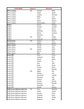
SolidWorks 2011Lesson 1Introduction to Motion Simulation and ForcesBasi c MotionIn this lesson, we will perform a basic motion an alysis u sin gAnalysisSolidWorks Motion to simulate the weight of a vehicle on the jack anddetermine the torque required to lift it. Engineers can then use thisinformation to choose the required electric motor to drive the car jack.Case Study: CarJack AnalysisA mechanical jack is a device that lifts heavy equipment. The mostcommon form is a car jack, floor jack, or garage jack which liftsvehicles so that maintenance can be performed. Car jacks usually usemechanical advantage to allow a human to lift a vehicle. Morepowerful jacks use hydraulic power to provide more lift over greaterdistances. Mechanical jacks are usually rated for a maximum liftingcapacity (e.g., 1.5 tons or 3 tons).Because this is our first motion analysis, no contact is used and thetilting motion of the jack is prevented with the help of the mates.ProblemDescriptionStages in theProcessThe car jack will be driven at a rate of l 00 RPM and will be loadedwith a force of 8,900 N., representing the weight of a vehicle.Determine the torque and power required to lift the load through therange of motion of the jack. Create a Motion Study.This will be a new motion study. Add a rotary motor.The rotary motor will drive the jack. Add gravity.Normal gravity will be added so that the weight of the car jackcomponents are considered in the calculations. Add the weight of the car.The weight of the car will be added as a downward force on theSupport.10
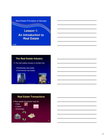
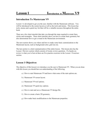
Lesson 1SolidWorks 2011Introduction to Motion Simulation and Forces Calculate the motion.The default analysis will run for five seconds but we will increase itto allow the jack to extend fully. Plot the results.We will create various plots to show the torque and power required.1Ensure that SolidWorks Motion isadded in.Under Tools, Add-ins, make sureSolidWorks Motion is checked.2Open an assembly file.Open Car Jack from theAdd-InsActiveStart UpAdd-l'tsA8 SoltdWorks Premium Add-instJ :Jt :D Instant WebsiteLJ ctrutworuEJ t: FeatureWorksEJGPhotoView '!S anToD360'rhLessonOl \Case Studies folder.rtl)di:::::.;,[[]SolidWorks ToolboxE)SolidWorks Workqr PDMEJ 1f SolidWorics Toobox BrowserI"Jw Soldworu u.,.,2011EJI:IroiAn "''B SolidWorks Add-im[J!CJ['jAutotraceSolidWorks Flow SimulationSolidWorks2011XPS Driver[EJ[C)EJEJ Other Add-insEJDa ntr 11
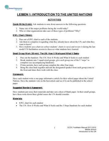
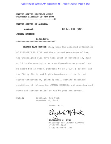
SolidWorks 2011Lesson 1Introduction to Motion Simulation and ForcesaSet the doc ument units.SolidWorks Motion uvth ;document.dgcy ment units SGt in the SolidWorksTools, Options, Document Properties, Units.ClickSelect MMGS(millimeter, gram, second)for theUnit system.Thiswill set our length units to millimeters and force to Newtons.Document Properties - Units Drafting Standaffi. Annotations ·DimensionsVirtual Sharps! J . Tabl5Detailingl'---DocumentProper t esSys Options'------------------------- ------,Unit system.'MKS(me:ter, kilogram, second)CGS {centimeter, gram, second)10 MMGS (millimeter, gram, second)IPSf(nc:h, pound, second)CustomGrid/SnapUnitsModel DisplayImage QualitySheet: MetalPlane: DisplayTypeBasicUnitslengthDual ass/Section PropertiesLengthmilhmetersMa 'PowerEne g y121J"II.12secondnewtoowan"'" I.12.12.12FractionsI HoreIIIJII
Lesson 1SolidWorks 2011Introduction to Motion Simulation and Forces4Change to the Motion Study.Click on the Motion Study l tab that appears at the bottom left-handcorner of the window. If this tab is not visible, select Motion Manageron the View menu. Car)ack (Default DisplayState-1 }'@} Sensors --lAJ Annotations!. Front Plane[. &: Top Plane! . Right PlaneL Originffi. (f) Base l (Default«Default P -· (·)SprocketlinH l (Default Dr1J-- {-}Sprock:etlink4 1 (Default«D -- (-) link l (Default«Default PhriJ (- ) Link l (Defautt«Default P -- (.) Side l support l (Default« · (-} Side l !mpport 2 (Default Di)--- (- )Sprocketlinkl l {Oefault Deffi. H Sprocketlink2 1 (Default«De -- (-} link 3 {Default Oefault Phci'J· (-) link 4 (Default Default Ph:iJ--- (-}Support ! (Default Default -- (-) Screw rod l (Oefault«Oefaul l@@ Mate I fiJ *ctrl lil1I''Ilights and Cameras,IFeatureManager Tree-IHide All TypesPlanes- Live Section PlanesAx.,;Tempoca y Ax.,;Origins Coordinate Syst'1.nk V d bl.,;Show Bodces------Tc}O\barsI WorkspaceI [gj I Full SmonV,IMod;ty Di pl y :,7, ICtri RRed"wScreen CaptureFeatureManager Tree AreaToolbarsFllF9jIIFlOr-:'! i T.(j !"";"MotionManagerCustomize MenuDriving MotionJMotion can be driven by gravity, springs, forces or motors. Each hasdifferent characteristics that can be controlled.Introducing: MotorsMotors can create either linear, rotary or path dependent motion or toprevent motion. This motion can be defined in a number of differentways. Constant SpeedThe motor will drive at a constant velocity. DistanceThe motor will move for a fixed distance or degrees. OscillatingOscillating motion is a back and forth motion at a specific distanceat a specified frequency. SegmentsMotion profile is constructed from segments of the most commonlyused functions such as linear, polynomial, half-sine and others. Data PointsInterpolated motion is driven by a tabular set of values.13
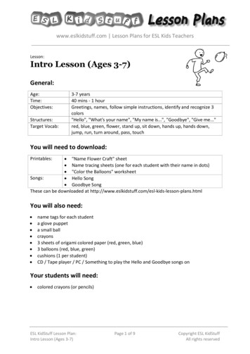
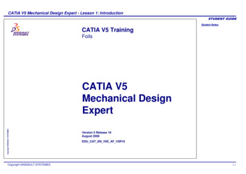
Lesson 1SolidWorks 2011Introduction to Motion Simulation and Forces ExpressionThe motor canbe driven by a funGtion created from existingvariables and constants. Servo MotorThe motor used to implement control actions for the event-basedtriggered motion.Where to Find It 5On the MotionManager toolbar, click Motor .Create a Motor that drives the Screw rod at 100 RPM.Click Motor on the Motion Manager toolbar.Under Motor Type, select Rotary Motor.Under Component Direction, select the cylindrical face of theScrew rod part as shown in the figure. The Motion Direction fieldwill automatically populate the same face to specify the direction.Use the Reverse Direction button to orient the motor (see the figure).Leave the Component to move relative to field empty. This ensuresthat the motor direction is specified with respect to the globalcoordinate system.Under Motion, select the Constant speed and enter a value of100 RPM.Click OK.··. atOd the graph to erVargeImportant!14Make sure that the motor is oriented as shown in the figure.
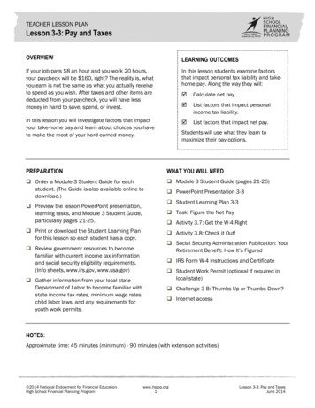
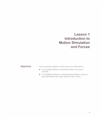
Lesson 1SolidWorks 2011Introduction to Motion Simulation and ForcesClick the graph in the PropertyManager to view the enlarged plot.Displacement .vs. Time200.00 -,-------,150.0050.000.00 ----- i----o--- - - -- --- -- - ---t-- --10.00.81.62.43.24.0Time (s)4.85.66.47.28.0Close the graph plot and click OK to close the Motor PropertyManager.6Type of Study.Make sure that the Motion Type of Study fieldshows Motion Analysis.GravityGravity is an important quantity when the weight of a part has aninfluence on its simulated motion, such as a body in free fall. InSolidWorks Motion, gravity consists of two components: Direction of the gravitational vector Magnitude of the gravitational accelerationThe Gravity Properties allows you to specify the direction andmagnitude of the gravitational vector. You can specify the gravitationalvector by selecting the X, Y and Z direction or by specifYing areference plane. The magnitude must be entered separately. The defaultvalue for the gravitational vector is Y and the magnitude is29806.55 mm/sec or the equivalent in the currently active units.15
SolidWorks 2011Lesson 1Introduction to Motion Simulation and Forces7Apply Gravity to the assembly.Click Gravity on the Motion Manager toolbar. ' xFor Gravity Parameters, Direction Reference, arametersselect the Y direction. . I\ ')(G1Yl.I 1' 1ZUnder Numeric gravity value, type in a value of9806.65 mm/secA2.Click OK.ForcesForce entities (including both forces and moments) are used to eflectthe dynamic behavior of parts and sub assemblies of a motion modeland are usually a representation of some external effect acting on theanalyzed assembly.Forces may resist or induce motion, and are defined using similarfunctions that are used to define motors (constant, step, function,expression or interpolated).Forces in SolidWorks Motion can be divided into two basic groups: Action ForcesA single applied force or momentrepresenting the effect of the externalobjects and loadings on the part orsubassembly. The weight of the vehicleapplied on the car jack or anaerodynamic force on the car body are examples of action forces. Action and Reaction ForcesA pair of forces or moments, both action and correspondingreaction, are applied on the parts or subassemblies.A spring force could be understood as action and reaction forcebecause both are acting on the same line of action and acting on theassembly at the spring mount points. Another example would be aperson pushing with his/her arms on the two opposing parts of anassembly. Such a person can then be represented in the motionanalysis by a pair of two opposing forces of equal magnitude on thesame line of action, i.e. action and reaction forces.UnderstandingForces16A force can define load or compliance on a part. SolidWorks Motionprovides the following type of forces:
Lesson 1SolidWorks 2011Introduction to Motion Simulation and ForcesApplied ForcesApplied forces are forces that define loads at specific locations on apart. You must provide you own description of the force behavior byspecifying a constant force value or a function expression. The appliedforces available in SolidWorks Motion are the applied force, appliedtorque, action/reaction force and action/reaction torque.The orientation of action-only forces can be fixed or at relative to theorientation of any part in the mechanism.Applied forces are used to model inputs such as actuators, rockets,aerodynamic loads and many more.Force DefinitionWhere to Find ItTo define a force the following information must be specified: Part or parts on which the forces act. Point of the force application. Magnitude and direction of the force. On the MotionManager toolbar, click Force u;. . Select Action OnlyForce Direction in the PropertyManager.The force direction is based on the reference part Adrononly(I) Actioo &. reactionyou select in the Force Direction box. Anillustration below gives you the three cases on howthe force direction changes based on the selectedreference parts.o II IIIIForce relative ID:(1?1 Assembly arigtl( ;. Selected component:Case 1Direction of force is based on a fixed component.If fixed component is the assembly origin then the initial orientation ofthe force will be held constant throughout the simulation.Reference Fixed Component0 v- 17
Lesson 1Introduction to Motion Simulation and ForcesCase 2SolidWorks 2011Direction of force is based on the selected moving component,which is also the component on which you want to apply theforce.If the part to which the force is applied is used as the reference datum,then the force will remain locked in its relative orientation to the bodyover the entire simulation time (i.e. it will stay in alignment with thegeometry on the body used to define the direction).Reference Rotating Component .r :.F1xed ComponCase 3Direction of force is based on the selected moving componentwhich is different from the component on which you want toapply the force.lf another moving part is used as the reference datum, the direction ofthe force will change based on the relative orientation of the referencebody to the moving body. This is hard to visualize easily, but if youapply the force on a body that is held locked in position, and use arotating part as the reference datum, you should see the force rotates inconcert with the reference body.Reference Rotating Componentrc,c· · ·-.'.L.I NoteMake sure that the gravity symbol shows the orientation in thenegative Y direction.18F
SolidWorks 2011Lesson 1Introduction to Motion Simulation and Forces8Create a force of 8900 N to simulate the weight of the car on thecar jack.Click Force II\ on the Motion Manager.For Type, select Force.Under Direction, select Action Only.Under Action part and point of application of action, select thecircular edge on component Support-! (see image below).For Force Direction, select the vertical edge on the Base-lcomponent.The default force direction is defined by the circular edge selected inNotethe Action part and point of application of action field, i.e.perpendicular to the plane of the edge. Because the default direction iscorrect in this case, the edge selected in the Force Direction field is notrequired and is done solely for the educational purpose.Under Force Function, select Constant. Enter a force value of8900 N.Make sure that the force is directed downwards.NoteClick OK to close the Force/Torque PropertyManager.9Run the Simulation.Click Calculate a1.l! The simulation will calculate for 5 seconds.19
Lesson 1Introduction to Motion Simulation and ForcesSolidWorks 201110 Run the Simulation for 8 seconds.Drag the end time key to 8 seconds on the timeline and recalculate.ResultsThe primary output from a motion study is a plot of one parameterversus another, usually time.Once the motion is calculated plots can be created for a variety ofparameters. All existing plots will be listed at the bottom of theMotionManager tree.Plot CategoriesSub-CategoriesPlots of the following categories can be created: Displacement Displacement Acceleration Forces Momentum Energy Power Other quantitiesWithin each of the categories, plots can be created for:XYZ Position Trace Path Linear Displacement Linear Velocity Linear Acceleration Angular Displacement Angular Velocity Angular Accele
In this lesson, we will perform a basic motion analysis using SolidWorks Motion to simulate the weight of a vehicle on the jack and determine the torque required to lift it. Engineers can then use this information to choose the required electric motor to drive the car jack. A mechanical jack is a device that lifts heavy equipment.