Transcription
System GalaxyHardware ManualVersion 2.4June 19, 2004System Galaxy Hardware Manual1
Information in this document is subject to change without notice. No part of this document may be reproduced,copied, adapted, or transmitted, in any form or by any means, electronic or mechanical, for any purpose, withoutthe express written consent of Galaxy Control Systems. Copyright protection claims include all forms andmatters of copyrighted material and information, including but not limited to, material generated from thesoftware programs which are displayed on the screen such as icons, look and feel, etc.Revision History1.0First Release1.108/18/2000 – updated diagrams06/22/20001.209/06/2000 – updated diagrams, added CCTV string chart to Appendix1.311/22/2000 – added Lantronix Configuration section26/19/2002 -- updated for SG version 4.52.111/26/2002 -- reformatted, added AMM Aux, new PRM, Cypress clock, GCS LantronixConfig2.212/30/2002 -- revised network bridge section2.305/01/2003 -- revised Lantronix programming (Access Dynamic), added Troubleshooting2.406/19/2004 -- added 508i documentation from addendum, added Sagem readersGalaxy Control Systems3 North Main StreetWalkersville, MD 21793Phone: (301) 845-6600Fax: (301) 898-3331Email: info-usa@galaxysys.comInternet: http://www.galaxysys.comCopyright 2000 Galaxy Control Systems All Rights Reserved2System Galaxy Hardware Manual
Table of ContentsT ABLE OF CONTENTS . 3SYSTEM OVERVIEW . 84 Introduction. 84 System Components . 84 Site Plan . 94 PC Requirements.10Minimum Requirements for a Stand-Alone Configuration . 10Minimum Requirements for a Network Configuration. 104 Simple System Configuration .12500 SERIES CONT ROLLER - DESCRIPT ION . 134 Introduction.134 508/502/508i Specifications.134 508/502 Central Processing Unit .144 508i Central Processing Unit .15508/502 Option Switches (S3) . 17508i Option Switches (S3). 18508/502/508i Unit Number Switches (S4) . 20508/502/508i Baud Switches (S5) . 21508/502/508i Reset Switch (S6). 2150/502 LEDs. 22508i LEDs. 22System Galaxy Hardware Manual3
508/502 Batteries (B1 and B2). 23508i Battery (B1) . 23508i Jumpers. 23508i Unused Connectors (J7, J8). 23508/502 Ribbon Cables. 234 508/502/508i Back Plane .24508/508i Model Back Plane. 24502 Back Plane. 254 Dual Port Interface (DPI) .26DPI - Unsupervised Door Version. 27DPI - Supervised Door Version . 284 Network/Terminal Interface.31Fiber Option . 32500 SERIES CONT ROLLER - INST ALLAT ION . 334 508/502 Main Installation Checklist.334 508i Main Installation Checklist.334 Mounting the Controller - 508/502/508i.344 Controller to Controller Connections - 508/502/508i.35Standard Copper Wiring of Controller Loop. 36Using Fiber between Controllers. 37Using Line Drivers Between Controllers. 38Connecting Loops using a Network Bridge - 508/502. 39Connecting Loops using a Network Bridge - 508i . 414 PC to Controller Connections - 508/502/508i .42Direct Connection - 508/502/508i . 42Dial-up Connection - 508/502/508i . 42TCP/IP Connection - 508/502 . 43TCP/IP Connection - 508i . 434 Controller Power Connections - 508/502/508i.444 Program IP Address - 508i.454System Galaxy Hardware Manual
4 Load Flash - 508i.46Load Flash Using HyperTerminal. 46Load Flash Using Loader (v.6 Maintenance Release). 47CARD READERS & KEYPADS. 484 Description .484 Installation .48Infrared Swipe Readers and Keypads. 50Wiegand Swipe Reader. 51Magnetic Stripe Reader. 52Barcode Readers. 53Essex keypads. 54Proximity Readers. 55Sagem Readers . 57Wiring Readers for Anti-Passback. 61PARALLEL READER M ODULE. 634 Description .634 Installation .63Set the Jumpers . 64Connect the Readers. 65Connect the Module to the Controller . 65Tape off the J4 IN/OUT wires. 65Set the DPI to 12 V. 65Special Notes for Essex Keypads. 65DOOR CONT ACT /REQUEST TO EXIT . 664 Description .664 Installation .66LOCK WIRING . 684 Description .68System Galaxy Hardware Manual5
4 Installation .68Fail Safe Wiring. 69Fail Secure Wiring. 69PROGRAMMING READER. 704 Description .704 Installation .70Connecting Reader to PC. 70Programming Reader Configuration. 70ALARM M ONITORING MODULE (AMM) . 724 Description .724 Installation .73AMM to Controller Wiring. 73AMM to Device wiring. 73AMM Relay Wiring. 74AMM Monitored Auxiliary Power Wiring. 74OUT PUT RELAY M ODULE (ORM ) . 764 Description .764 Installation .77Relay Power . 77Optional Relay Bussing. 78Tamper Connection. 79ELEVATOR/HVAC CONT ROL . 804 Description .804 Installation .80Odd DPI Port Configuration. 80Even DPI Port Configuration. 80GENERAL PURPOSE INPUT /OUTPUT PORT . 826System Galaxy Hardware Manual
4 Description .824 Installation .82Connecting Inputs. 82Connecting Outputs. 83CYPRESS CLOCK . 854 Description .854 Installation .85LANT RONIX CONFIGURAT ION . 874 Description .874 Installation .87Setup Using GCS Lantronix Utility (Recommended) . 87Setup Using Hyperterminal . 894 Troubleshooting .92Helpful Commands. 92Helpful Utility Buttons. 94APPENDIX. 964 Index of 508i Commands .964 Unit Number Table.984 ASCII STRINGS FOR CCTV.101System Galaxy Hardware Manual7
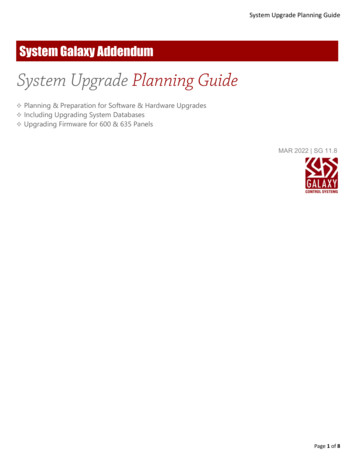
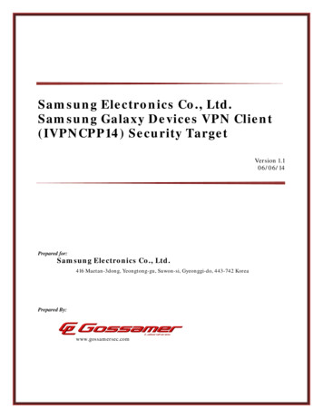
System OverviewIntroductionSystem Galaxy is an enterprise-class integrated access control and security management system. Designedfor use in a wide variety of security applications, the System Galaxy system allows users to monitor andcontrol many facility and security functions.The System Galaxy system was designed with software and hardware components that combine AccessControl, Alarm Monitoring, CCTV, Photo Imaging/Badging, Photo Verification, Elevator Control, HVAC andLighting within a facility or multiple facilities.System ComponentsSystem Galaxy consists of both electronic hardware and software components that work together to controland monitor a facility. The software components are used to configure and monitor the operation of thehardware, while the hardware components implement the actual security and control functions.The System Galaxy hardware consists of five major components: the System Galaxy controller units,credential readers, alarm monitoring modules (AMMs), the output relay modules (ORMs), and personalcomputers (stand-alone or networked).The System Galaxy software is based on a central database that contains all the information necessary for thefunctioning of the hardware. The database also records all events generated by the hardware. The SystemGalaxy software provides easy access to system monitoring, hardware control, report generation, and CCTVand badging functions.System Galaxy software can be set up before or after the System Galaxy hardware is installed. However,the hardware configuration must be available to provide information such as unit and serial numbers.Installation and Configuration of the System Galaxy software is explained in detail in the Software Guide.The following diagram represents the basic interaction between all the elements of System Galaxy.8System Galaxy Hardware Manual
Site PlanThe first step to a successful installation is to make a site plan. This is a drawing indicating the location of eachcomponent of the access system. It should include the controllers, power supplies, PC(s), card readers and/orkeypads, door contacts, door strike sensors, all alarm points and all wiring lengths. Have the customer provideblueprints of the building or buildings to assist you with this task. It is very helpful to have access to theelectrical drawings as well. Always remember to have your site plans approved by the local regulatoryagency to assure that your installation will conform to all safety codes. When drawing any site plan, keepthe following recommendations in mind:1.Keep all wire (power, network, strike, door sensor, alarm and reader) well away from high frequency andhigh power lines. If the crossing of these lines is unavoidable, do so at a 90-degree angle. This minimizesthe electrical interference, which could disrupt the system’s normal operation.2.Use 22 AWG (Beldon #9946 - PVC rated) shielded wire for readers, Alarm Monitoring Modules, and OutputRelay modules; 22 AWG shielded twisted pair for network wiring (Beldon #8723 - PVC rated); and 18 AWGshielded wire for door release connections. The shields should be grounded at the controller end only.Dedicated conduit is highly recommended for the wiring. Be aware of any special requirements for plenumrated cable.3.The controller should be centrally located in reference to the doors and/or alarm points that it controls. Thiswill prevent many long wire runs. It should also be located in a secure area to prevent tampering.4.If the distance between network controllers exceeds 1000 feet (at 9600 baud), line drivers or short haulmodems are required. If the distance between controllers includes electrical interference, fiber connectionsmay be required for clean operation.System Galaxy Hardware Manual9
PC RequirementsThe computer system requirements vary if you are configuring a Stand-Alone PC, Network DatabaseServer, or Network Client. Please refer to the appropriate section for the minimum requirements foryour system.Minimum Requirements for a Stand-Alone Configuration-IBM Compatible PC with an Intel Celeron 500 MHz processor (or higher)-128 Mb of RAM-Windows NT Workstation 4.0 with Service Pack 5, or Windows 2000, or Windows XP-Microsoft Internet Explorer version 4.0 or higher (cannot be replaced by Netscape Navigator)-2 GB of free hard drive space to install System Galaxy; more space needed depending on size ofdatabase.-Standard graphics card capable of 24-bit color at 1024 x 768 resolution-17” monitor (or larger)-Standard Parallel Port-COM (serial) ports as required:-One COM port per direct-connection loop-An additional COM port if using an RS-232 programming reader-One COM port if using a serial Port UPS-One serial Port UPS (recommended)-Any Windows compatible printer for report printingMinimum Requirements for a Network ConfigurationA Network Configuration requires setting up both a Network Database Server and a Network Client, each ofwhich has different system requirements. Please refer to the appropriate section when setting up the system.Network Database ServerNote: the recommended size of the Database Server depends on the amount of traffic that thesystem will generate. If you will be using System Galaxy for a large system (multiple loops, or aconstant stream of events), consider upgrading the database server to improve your performance-10IBM Compatible PC with an Intel Pentium II 300 MHz processor (or higher)System Galaxy Hardware Manual
-128 Mb of RAM (at least)-Windows NT Server 4.0 with Service Pack 5, or Windows 2000, or Windows XP-Hard drive space according to size of database.-Standard graphics card capable of 24-bit color at 1024 x 768 resolution-15” monitor (or larger)-One serial (COM) port-One serial port UPS-One NIC (network card)Network Client-IBM Compatible PC with an Intel Pentium II 300 MHz processor (or higher)-128 Mb of RAM-Windows NT Workstation 4.0 with Service Pack 5-Microsoft Internet Explorer version 4.0 or higher (cannot be replaced by Netscape Navigator)-2 GB of free hard drive space to install System Galaxy-Standard graphics card capable of 24-bit color at 1024 x 768 resolution-17” monitor (or larger)-Standard Parallel Port-COM ports as required:-One COM port per direct-connection loop-An additional COM port if using an RS-232 programming reader-One NIC (network card)-Any Windows compatible printer for report printingThe above specifications are minimum requirements only and are subject to change with the addition ofsoftware modules. Please contact Galaxy to ensure these are the latest specifications.NOTE: ANY deviation from these minimum requirements can cause System Galaxy to not function, or tooperate with degraded performance.System Galaxy Hardware Manual11
Simple System ConfigurationThe simplest system configuration would be one controller with one Dual Port Interface card, connected to onecard reader and the associated door controls. The card reader and door controls would be located at the pointof entry.Cabling between the card reader and the controller allows data to be sent to the controller and statusinformation to be sent back to the reader indicator lights. Additional cabling allows for the control of a doorrelease and a sensor signal to be sent to the controller when the door is opened.The Dual Port Interface card provides the surge protection necessary to protect the controller's CPU in the eventthat the controller receives a surge. The controller also provides the capability of monitoring and controllingalarm points. In addition to access control, alarm devices can be monitored and outputs can be activated, bysimply configuring an Input/Output Port or adding an Alarm Monitoring Module, and/or an Output RelayModule.Most small installations will consist of two to eight entry points connected to a single controller. For systemswith more than eight points of entry, multiple controllers are connected in a network ("loop") with one controlleracting as the primary unit and the others as secondary units. Only the primary controller is connected to a PC,either by an RS-232 connection, a modem connection, or a TCP/IP connection.Only one personal computer is required to program and monitor the system regardless of the number ofcontrollers in a system. However, multiple computers can be used in a System Galaxy System.12System Galaxy Hardware Manual
500 Series Controller - DescriptionIntroductionThe 500 Series controller is the central connection and control point for all the hardware. All system functions,such as cards being granted access and alarm devices monitoring the system, are controlled by this unit. Inaddition, all system events, such as card reads and alarm events, are recorded by the 500 Series control unitsfor eventual transfer to the PC. Up to 10,340 events are recorded in the controller buffer before the oldest eventis replaced by the most recent event.The 500 Series of controllers includes the 508 model, 502 model, and 508i model.The 508 and 502 model controllers are the original controller design, and feature a processor board that ismounted on the interior of the controller door.The 508i controller is a new version of the System Galaxy 500 series controller. The main feature of thiscontroller is the "native IP", which allows a 10Mb Ethernet connection via cat-5 cable connected directly to theCPU of the controller. The controller CPU is also new, and now connects to the backplane directly, without theuse of ribbon cables.The 508i controller requires at least the version 6 maintenance release of the System Galaxy software in orderto function; it requires the latest version of the Loader and Zlink that are included in that package. Please installthe 508i upgrade patch before upgrading the hardware.The 508i controller can be used in a loop with other 500 series controllers (508 and 502 models), as long as thesoftware is the correct version and all the controllers are running the same version of Flash.508/502/508i SpecificationsController Enclosure Dimensions: 21.00” x 14.00” x 6.25”: The controller enclosure is designed to be wallmounted.System Galaxy Hardware Manual13
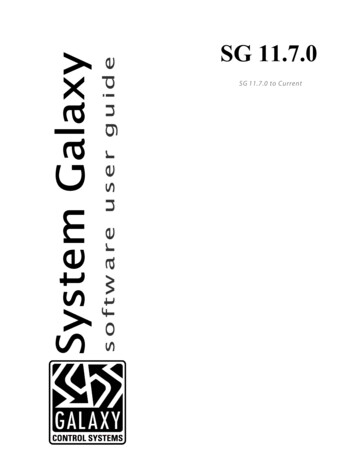
Input Power: 12 VDC @ 2 amps; minimum: 11.5 V, maximum: 14.0 V. This powers all boards, readers,AMMs, and ORMs. Lock Power and ORM relay power must be provided separately. When using morethan four proximity readers on one controller, it is necessary to use an additional power supply to power theadditional readers. Simply power the additional readers off of the second power supply instead of off the backplane. Most biometric readers must also be separately powered. Be sure to common the grounds between thepower supplies.Port Output: Form-C SPDT contacts; 24 VDC @ 1.5 amps maximum. Each port circuit provides relay contactsfor controlling external devices.PC to Controller Communications: Serial Asynchronous RS-232. Interfaces at 9600 baud.Connections: Straight lead barrier strips. All cable should be shielded and connected to the Power SupplyGround (the YELLOW pin of each port). DO NOT USE THE CONTROLLER CHASSIS FOR GROUND!Note: All maximum distance limits are estimates based on clear communication. If interference exists,distances must be reduced to maintain communication.ConnectionDistanceWirePC to 500 controller (RS-232):50 ft.22 AWG 4 conductor twisted pairBeldon #8723500 controller to Modem (RS-232):50 ft.22 AWG 4 conductor twisted pair8723500 controller to 500 at 9600 baud:1000 ft.*22 AWG 4 conductor twisted pair8723*Galaxy-provided line drivers can be used to go longer distances between controllers. If electrical interference ispresent between controllers, fiber connections are recommended for clean operation.All Galaxy readers:2500 ft.22 AWG 10 conductor9946All other readers:500 ft.22 AWG 10 conductor9946500 to AMM:500 ft.22 AWG 10 conductor9946500 to ORM:100 ft.22 AWG 10 conductor9946*Lock Hardware:----18 AWG 2 conductor minimum*Please note that these Beldon numbers refer to PVC-rated cable, not plenum-rated cable.508/502 Central Processing UnitThe Central Processing Unit (CPU) is the intelligence of the Galaxy controller. It is responsible for all decisionsmade by the system. It processes data consisting of card/PIN codes, door sensors, manual egresses, alarmconditions, network messages and PC data. The CPU generates signals for the door releases, reader LEDs,output relays, and controls network and PC communications.14System Galaxy Hardware Manual
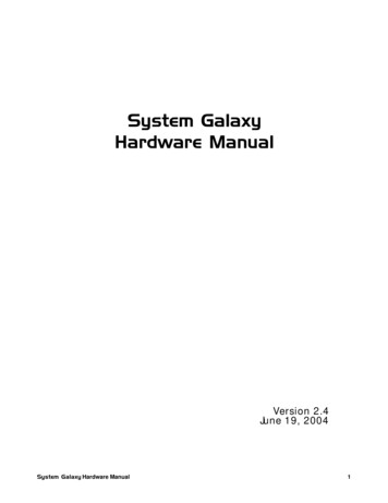
The CPU board has a smoked Plexiglas cover protecting it, which must be removed to gain access to thesystem dip switches and batteries. This cover should be reinstalled to protect the CPU from damage. Theillustration on the following page is of a Galaxy 500 Series CPU.The CPU includes Option Switches, Unit Number Switches, Baud Switches, a Reset Switch, LEDs, andBatteries. Each of these elements is discussed in the following sections.Controller CPUComponentsKA EPROM chipB Clock batteryC Memory batteryD Reset buttonE Option switchesF Unit # switchesAG Baud rate switchesH Power LEDI Receive LEDJ Transmit LEDLK, L, M Connectors forribbon cables frombackplaneH I JDB
8 System Galaxy Hardware Manual System Overview Introduction System Galaxy is an enterprise-class integrated access control and security management system. Designed for use in a wide variety of security applications, the System Galaxy system allows users to monitor and control many facility and security functions.