Transcription
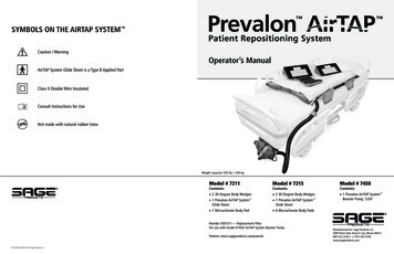
Prevalon SYMBOLS ON THE AIRTAP SYSTEM Patient Repositioning SystemCaution / WarningOperator’s ManualAirTAP System Glide Sheet is a Type B Applied PartClass II Double Wire InsulatedConsult Instructions for UseLATEXNot made with natural rubber latexWeight capacity: 550 lbs. / 250 kgModel # 7211Contents: 2 30-Degree Body Wedges 1 Prevalon AirTAP System Glide Sheet 1 Microclimate Body PadModel # 7215Contents: 2 30-Degree Body Wedges 1 Prevalon AirTAP System Glide Sheet 6 Microclimate Body PadsReorder #3010-F — Replacement FilterFor use with model #7450: AirTAP System Booster PumpPatents: www.sageproducts.com/patentsR21025B Rev.000 2016 Sage Products LLCModel # 7450Contents: 1 Prevalon AirTAP System Booster Pump, 120VManufactured for: Sage Products LLC3909 Three Oaks Road Cary, Illinois 60013800-323-2220 1 815-455-4700www.sageproducts.com
Prevalon Patient Repositioning SystemUSES: To assist and maintain proper patient positioning to offload the sacrum and control body heat and moisture.i CAUTION: Periodically check product for signs of wear. Replace if product is damaged. DO NOT launder any component of the AirTAP System. DO NOT plug Booster Pump into the bed. Glide Sheet for single patient use only. To assist with the repositioning of a patient.INTENDED CARE SETTINGS:Intended to be used in hospitals, healthcare facilities, and other environments where repositioning ofpartially–dependent or dependent patients is desired. This equipment is intended to be used for purposesstated in this manual. Any other use is prohibited.INDICATIONS: Use for patients who are dependent or partially-dependent and unable to participate in their own repositioning.CONTRAINDICATIONS:Patients who have thoracic, cervical, or lumbar fractures should not use the Prevalon AirTAP System (the“AirTAP System”) unless a clinical decision has been made by your facility. The equipment should not beused for patients that exceed the 550 lbs / 250 kg weight limit.i WARNINGS:Failure to comply with this Manual could result in injury or equipment malfunction. Alterationsor modifications to the System can affect the safety and functionality of the System and are strictly prohibited.Read and understand the entire Manual before using the system.AirTAP System Glide Sheet Always follow your facility’s safe patient handling policies and procedures. Patient repositioning should always be performed using at least two caregivers. DO NOT use the Glide Sheet to lift patients. To avoid potential skin injury, prevent patient’s heels and head from dragging across the bed during repositioning. To prevent injury or accidental inflation, ensure patient is not in contact with the Valve or Hose.AirTAP System Booster PumpTo reduce the risk of fire, burns, electrical shock, or injury:PRIOR TO USE: DO NOT use the Booster Pump in the presence of flammable anesthetics or other flammable gases or vapors.Perform a visual inspection of the AirTAP System. Examine the AirTAP System Glide Sheet (the “Glide Sheet”)and AirTAP System Booster Pump (the “Booster Pump”) for damage or wear that is potentially hazardousand could cause the AirTAP System to malfunction. If such damage is present, DO NOT USE. Examine thepower cord for damage. If the power cord is damaged, DO NOT USE the Booster Pump, as a damaged powercord may cause serious injury. Ensure all parts are present. If any parts are missing, DO NOT USE. DO NOT use the Booster Pump near water.IMAGING:The Prevalon AirTAP Glide Sheet with Microclimate Body Pad has been determined through scientificrationale to be MR Safe as defined in ASTM F2503-13 and IEC 62570:2014. MR safety testing wasdetermined to be not required as both the Prevalon AirTAP Glide Sheet and Microclimate Body pad areconstructed of non-metal materials. Based on rationale, the Prevalon AirTAP Glide Sheet with MicroclimateBody Pad is electrically nonconductive and not magnetic therefore reducing potential risks during MRscanning. Additionally, MR compatibility tests have shown no artifacts. DO NOT store or use the Booster Pump outdoors. DO NOT cover or block any openings on the Booster Pump. DO NOT tamper with or make any adjustments to any part of the Booster Pump. DO NOT let the Booster Pump cord hang over the edge of a table or counter. DO NOT operate the Booster Pump if it has a damaged cord or plug, if it is not working properly, or if it has been damaged ordropped. Contact Sage Products at 800.323.2220 for repair or replacement. DO NOT immerse the Booster Pump cord or plug in water. Keep cord away from heated surfaces. The AirTAP Booster Pump has been designed for use exclusively with the Sage air assisted technology products. DO NOT use Booster Pump during transport.The Booster Pump is not MR safe. Please follow your facilities protocol for using the Booster Pump in a MRenvironment.12
Prevalon SET UP THE BOOSTER PUMPPatient Repositioning System1. P lace the Booster Pump on its wheels near or under the foot of the bed.PART IDENTIFICATION30º BODY WEDGESAnchor WedgeSplit image: Booster atfoot of bed and hangingfrom footboardAIRTAP SYSTEM GLIDE SHEETUpper WedgeSTEP 1Head of Bed IndicatorEasy Roll HandlesHigh-Tech Fabric2. Plug the Booster Pump into the nearest electrical outlet.Plugging into wall outletSTEP 2Black Positioning HandlesCinch and Close Valves(available on both sides)Cord Reel1. With bed brakes locked and bed rails raised, place the bed in ahorizontal position, and at the caregiver’s waist level.STEP 1AIRTAP SYSTEM BOOSTER PUMPPoint of Care Power Buttonout of the patient’s reach and away from bed wheels so that it willnot be pinched or damaged and does not cause a tripping hazard.SET UP THE GLIDE SHEETCaregiver on each sideof bed while bed is flat.Patient in bedMicroclimate Body Padi CAUTION: DO NOT plug Booster Pump into the outlet on the bed.i WARNING: To avoid injury, route the Booster Pump power cordHose Retainer2. Lower the bed rail(s) on the side of the bed where the AirTAP GlideSheet (the “Glide Sheet”) will be placed. Place the folded Glide Sheetalongside the patient with the printed arrow pointing toward the headof the bed.Folded Glide Sheet onbed showing printedarrowFlexible Inflation HoseSTEP 2Power CordNozzle33. Unfold the Glide Sheet lengthwise and align the upper edge of theGlide Sheet with the patient’s shoulder.Folded Glide Sheet onbed showing printedarrow Place the Glide Sheet with Microclimate Body Pad beneath thepatient per your facility’s protocol.Hanging ClipNozzle RetainerSTEP 3NOTE: The edge of the Glide Sheet should overhang the side of thebed by approximately 2 inches on a standard bed.4
4. Ensure the patient is centered on the Glide Sheet and on the bed.Smooth out any wrinkles on the Glide Sheet and Microclimate Body Pad.POSITIONING AND BOOSTING THE PATIENTi WARNING: Make sure the bed rails are raised and the bed brakes are5. Raise the bed rails.locked. Always use at least two caregivers when Positioning and Boosting. To avoid potential skin injury, ensure the patient’s head and feet aresupported to prevent them from dragging across the bed.Patient centered ondeflated Glide SheetSTEP 4CONNECT THE BOOSTER PUMPSTEP 12. Remove the Body Wedges (the “Wedges”) if present by grasping thecorner and slowly rotating out.1. Open the Cinch and Close Valve (the “Valve”) closest to the BoosterPump by pulling the fastener tab up.Opening ValveSTEP 1One hand holds hose.Other hand separatesValvei WARNING: Before inflating, ensure lines and tubing are free tomove with the patient and that nothing obstructs the area over whichthe Glide Sheet will pass. Ensure that the Hose will move freely with theGlide Sheet.Close up of Power Buttonbeing pushedSTEP 4STEP 34. Insert the Hose into the Valve until the gray portion of the Nozzle isno longer visible.5. Pull the orange fastener tab to cinch closed around the Nozzle.Clinicians on either sideof bed with hands onblack handles of inflatedglide sheetSTEP 7STEP 46. Press the fastener tab together to secure and press down to ensure atight seal.i WARNING: To prevent injury or accidental inflation, ensurepatient is not in contact with the Valve or Hose at all times.STEP 63. E nsure the patient is centered on the Glide Sheet and the bed.2. Remove the Nozzle of the flexible inflation hose (the “Hose”) fromthe Nozzle Retainer on the Booster Pump.3. Grasp the Nozzle. With your free hand, separate the fabric of theValve.1. Caregiver A and Caregiver B stand on opposite sides of the bed. Lockthe bed brakes and raise the bed rails. Place the bed in a horizontalposition and at the caregiver’s waist level.4. While closely observing the patient, push the point of care powerbutton (the “Power Button”) on the Hose.5. Allow the Glide Sheet to fully inflate.i WARNING: Never leave the patient unattended while the BoosterPump is powered on or the Glide Sheet is inflated.6. Ensure the patient’s head and feet are supported.7. Use the black handles located on the edge of the Glide Sheet togently glide the patient to where the hips are aligned with the hingepoint on the bed.8. Turn the Booster Pump off by pressing the Power Button.9. Allow the Glide Sheet to fully deflate and smooth out any wrinkles inthe Glide Sheet or Microclimate Body Pad.TURNING THE PATIENT1. Caregiver A and Caregiver B stand on opposite sides of the bed. Lockthe bed brakes and raise the bed rails. Place the bed in a horizontalposition and at the caregivers’ waist level.2. Ensure the patient is centered on the Glide Sheet and the bed.3. While closely observing the patient, push the Power Button on the Hose.4. Allow the Glide Sheet to fully inflate.i WARNING: Never leave the patient unattended while theBooster Pump is powered on or the Glide Sheet is inflated.56
5. E nsure the patient’s head and feet are supported.2. Remove the Wedges if present by grasping the corner and slowlyrotating out.6. Caregiver A lower the bed rail where the Wedges will be inserted.3. Set the sending and receiving support surfaces as close together aspossible. Ensure the bed brakes are locked.7. Caregiver B use the Black Positioning Handles to secure the Glide Sheet.STEP 88. C aregiver A grasp the Black Positioning Handle on the Glide Sheetand insert the Anchor Wedge, tail first and with the black fabricfacing up, so that the Anchor is underneath the patient’s thighs.9. Caregiver B pull the tail through until it is taut.10. Caregiver A grasp the Black Positioning Handle on the Glide Sheetand insert the Upper Wedge at least one hand width away from theAnchor Wedge.STEP 10Sending and Receivingsurfaces pushed togetherClinician on opposite sidesGlide Sheet deflatedSTEP 35. Raise the exterior bed rails.6. Ensure the patient is centered on the Glide Sheet and the supportsurface.i WARNING: Before inflating, ensure lines and tubing are free tomove with the patient and that nothing obstructs the area over whichthe Glide Sheet will pass. Ensure that the Hose will move freely with theGlide Sheet.11. The caregiver on the side of the bed where the Booster Pump isconnected pushes the Power Button to turn the Booster Pump off.7. While closely observing the patient, push the Power Button on theHose.12. Perform a microturn while the Glide Sheet is deflating, if needed.With both caregivers on the same side of the bed, grasp the BlackPositioning Handles, palms down.8. Allow the Glide Sheet to fully inflate.i WARNING: Ensure the Glide Sheet is fully inflated prior toGently pull, DO NOT lift, until the patient is positioned at thedesired angle.transfer. If the Glide Sheet is not fully inflated, injury to the patient orcaregiver could occur or the Glide Sheet may not perform as expected.STEP 129. Ensure the patient’s head and feet are supported.13. After the Glide Sheet is fully deflated, check to ensure the patient’ssacrum is offloaded.14. Raise the bed rails.i WARNING: DO NOT use the Glide Sheet to lift patients.STEP 10Show mid transfer shot10. With a minimum of one caregiver on each side, the caregiver on thesending surface gently pushes the patient toward the receiving side.11. The caregiver on the receiving surface grasps the handles and helpsglide the patient into position.12. Ensure the patient is fully on the support surface.STEP 1313. Turn the Booster Pump off by pressing the Power Button.STEP 11LATERAL TRANSFERthe Lateral Transfer. Exterior bed rails on both surfaces should beraised prior to transfer to prevent the patient from falling. If there areno bed rails used, the caregivers are responsible for making sure thepatient does not reach outside the boundaries of either support surface. To avoid potential skin injury, ensure the patient’s head and feet aresupported to prevent them from dragging across the support surface.1. Lock the bed brakes and raise the bed rails. Place the sending supportsurface in a horizontal position and at the caregiver’s waist level.14. Allow the Glide Sheet to fully deflate and smooth out any wrinklesin the Glide Sheet or Microclimate Body Pad.15. Slightly separate the receiving and sending surfaces until the rail onthe receiving surface can be accessed.i WARNING: Always use at least two caregivers while performing74. Set the receiving support surface slightly above, but no more thanone inch above the sending support surface.16. Raise the bed rails.Show mid transfer shot17. Use the Hanging Clip to hang the Booster Pump from the patienttransport surface.STEP 178
EASY ROLL HANDLES1. The gray Easy Roll Handles may be used to assist with positioningthe patient. Always follow your facility’s safe patient handlingprocedures.Close up on extensionhandlesAIRTAP SYSTEM BOOSTER PUMPFILTER REPLACEMENTPART IDENTIFICATIONSTEP 1Flexible Inflation HoseMotor HeadCHANGING THE MICROCLIMATE BODY PADReplace only with Microclimate Body Pads (Model #7250). Align thetop edge of the Microclimate Body Pad with the top edge of the GlideSheet. Dispose the soiled Microclimate Body Pad per your facility’swaste management protocol.Power Cord Inletand Retention TabTO REMOVE THE BOOSTER PUMP1. Grasp the Nozzle. With your free hand, pull loose the orange fastener tab.Nozzle RetainerReplaceable Filter2. Pull the Hose free from the Glide Sheet.3. Press down on the orange tab to close the Valve.4. Place the Nozzle in the Nozzle Retainer and secure the Hose in theHose Retainer.Point of CarePower Switch5. Unplug the cord from the wall electrical outlet and wrap it aroundthe cord reel at the rear of the Booster Pump.CLEANING AND DISINFECTINGFilter CanisterFollow your facility’s infection control policies and procedures regarding the cleaning of equipment and the use ofdisinfectants on cleaning facility surfaces in contact with patients’ skin.BOOSTER PUMPUnplug the Booster Pump prior to cleaning. Clean the outside of the Booster Pump with a large, cloth dampened withmild detergent solution. Ensure the cloth is not so wet as to drip liquid or cause liquid to pool on the Booster Pump. Toprevent damage to the operating parts inside the Booster Pump, do not allow liquid to seep into the openings.Thumb ScrewHose RetainerDisinfect the Booster Pump using a hospital grade disinfectant in accordance with Manufacturer’s instructions.GLIDE SHEET AND BODY WEDGESIf the Glide Sheet or Body Wedges become soiled, wipe with a damp cloth to clean. DO NOT launder as laundering willcompromise the function of this device.910
FILTER REMOVAL AND REPLACEMENT:5. Remove the filter canister and remove the filter by pulling it off themotor head. (Dispose of the filter per your facility’s policy).1. U nplug the Booster Pump from the wall.STEP 56. P lace the new filter over the end of the motor head and ensure thatthe threaded rod passes through the end of the filter.STEP 12. R emove the Hose by removing it from the Nozzle Holder and HoseRetainer.STEP 67. P ull the elastic end of the filter all the way down so that it covers theyellow band.STEP 28. S lide the filter canister over the motor head, allowing the rod to passthrough the bottom hole.3. R emove the power cord by lifting the retention tab upwards andpulling the cord from the receptacle.STEP 7 eplace the thumbscrew back on the rod and tighten in a clockwise9. Rdirection until snug.iCAUTION: If the thumbscrew overtightened, the filter will notwork properly.10. Lift the gray retention tab on the motor head and fully insert the pluginto the receptacle opening. Push the retention tab downward to lockthe tab into place.STEP 34. L ocate the thumbscrew inside the cord reel opening. Remove thethumbscrew by turning in a counterclockwise direction.STEP 1011. Place the nozzle end in the Nozzle Holder and snap the Hose into HoseRetainer.STEP 4STEP 111112
REMOVING LINENS6. Starting at the head of the bed, lift the corners of the linen offthe mattress.i WARNING: Make sure the bed rails are raised and the bed brakesare locked. Always use at least two caregivers when changing linensusing the AirTAP System. To avoid potential skin injury, ensure thepatient’s head and feet are supported to prevent them from draggingacross the bed.STEP 61. Caregiver A and Caregiver B stand on opposite sides of the bed. Lockthe bed brakes and raise the bed rails. Place the bed in a horizontalposition and at the caregiver’s waist level.7. B oth Caregivers hold the Glide Sheet with one hand and gently pull thelinen toward the foot of the bed, allowing it to pass below the inflatedGlide Sheet.2. Remove the Wedges if present by grasping the corner and slowlyrotating out.STEP 13. Ensure the patient is centered on the Glide Sheet and the Glide Sheetis centered on the bed.iWARNING: Before inflating, ensure lines and tubing are free tomove with the patient and that nothing obstructs the area over whichthe Glide Sheet will pass. Ensure that the Hose will move freely withthe Glide Sheet.STEP 78. Caregiver A hold the mat in place. Caregiver B remove the linen fromthe bed and follow your facility’s protocol for handling soiled linens.4. While closely observing the patient, push the Power Button onthe Hose.STEP 89. Caregiver B turn the Booster Pump off by pressing the Power Button.STEP 45. Allow the Glide Sheet to fully inflate.i WARNING: Never leave the patient unattended while the BoosterPump is powered on or the Glide Sheet is inflated.STEP 910. Allow the Glide Sheet to fully deflate and smooth out any wrinkles inthe Glide Sheet or Microclimate Body Pad.STEP 101314
PLACING LINENS7. Allow the Glide Sheet to fully inflate.i WARNING: Never leave the patient unattended while thei WARNING: Make sure the bed rails are raised and the bed brakesBooster Pump is powered on or the Glide Sheet is inflated.are locked. Always use at least two caregivers when changing linensusing the AirTAP System. To avoid potential skin injury, ensure thepatient’s head and feet are supported to prevent them from draggingacross the bed.1. Caregiver A and Caregiver B stand on opposite sides of the bed. Lockthe bed brakes and raise the bed rails. Place the bed in a horizontalposition and at the caregiver’s waist level.2. Remove the Wedges if present by grasping the corner and slowlyrotating out.STEP 18. B oth Caregivers hold the Mat with one hand and gently pull the linen towardthe foot of the bed, allowing it to pass below the inflated Glide Sheet.STEP 89. Once the linen is at the bottom edge of the Glide Sheet, Caregiver Ahold the mat in place and Caregiver B turn the Booster Pump off bypressing the Power Button.3. E nsure the patient is centered on the Glide Sheet and the Glide Sheetis centered on the bed.4. Tuck the Bottom edge of the linen beneath the patient’s pillow, GlideSheet, and shoulders.STEP 910. Allow the Glide Sheet to fully deflate. Anchor the bottom corners ofthe linen and smooth out any wrinkles in the Glide Sheet orMicroclimate Body Pad.STEP 45. Anchor the top corners of the linen to the mattress.iWARNING: Before inflating, ensure lines and tubing are free tomove with the patient and that nothing obstructs the area over whichthe Glide Sheet will pass. Ensure that the Hose will move freely withthe Glide Sheet.STEP 10STEP 56. Caregiver A closely observe the patient and hold the Glide Sheet in Place.Caregiver B turn the Booster Pump on by pressing the Power Button.STEP 61516
REPAIR:BOOSTER PUMP TECHNICAL SPECIFICATIONSContact Sage Products at 800.323.2220 for repair or replacement.Product Code7450Input Rating120 V AC / 60 Hz / 10 AMPAmbient Operating Range Max50 F (10 C) - 86 F (30 C)Relative Humidity Operating Range10 - 70% Non-CondensingOperating Pressure70 kPa - 106 kPaOuter Dimensions17 1/2”H x 14”W x 12 1/2”D (445mm x 356mm x 318mm)Gross Weight (G.W.)G.W.: 12.5 lbs. (5.7 kg)ClassificationClass II With Functional EarthDegree of Protection Against Ingress of WaterIPXOMode of Operation-Duty Cycle30 sec on 1 min off 5 Cycles w/30min restStorage / Transport Temperature24.8 - 158 F (-4 - 70 C)Storage / Transport Relative Humidity10% to 90%Storage / Transport Atmospheric Pressure Range500 to 1060 hPaStandards - UL / EN / CSA / IEC 60601-1UL 60601-1 Medical Electrical Equipment 2nd Edition–3rd EditionUL ClassificationIEC 60601-1:2012, Edition 3.1Characteristics-MotorTwo state, single speed, 120 volts, double ball bearings, low-noise bypassdischarge, 40 peak horsepowerCharacteristics-Airflow5,900 ft/min / 1,798 m/minCharacteristics-Hose8 ft x 1.5 in / 3.048 m x 3.81 cm commercial strength flexible hoseCharacteristics-NozzleCustom heavy duty fast connectorCharacteristics-Cord / ConnectorHeavy duty medical grade - grounded IEC femaleDisposalFollow national requirementsConsult Instructions for UseNo applied partsApplied Partsi Caution / WarningDO NOT use in the presence of flammable anesthetics and other flammable gasesor vaporsFilter5 Micron Poly FilterE47268017Refer to accompanying documentsMedical equipment with respect to electric shock, fire and mechanicalhazards only, in accordance with ANSI/AAMI ES60601-1 and 1 2012, CAN/CSAC222 NO. 60601-1-114, ANSI/AAMI/IEC 60601-2.18
3 4 SET UP THE BOOSTER PUMP 1. Place the Booster Pump on its wheels near or under the foot of the bed. 2. Plug the Booster Pump into the nearest electrical outlet.