Transcription
Commercial ProductsHydraulicsHydrostaticsSchematicsand TestEquipmentPart No. 82356SL, Rev. B
IntroductionTurf mowing equipment was very cumbersome andinefficient when it was first developed back in theearly 1900’s.Improvements were made through the years of Turfequipment’s development, but it wasn’t until hy draulics became a part of the design that significantimprovements were made.Use of hydraulics has increased to form a majorportion of turf product designs. Increases efficiency,reliability, lowered maintenance costs, safer prod ucts and improved operator comfort are all by products of the increase in use of hydraulic sys tems on turf products.An understanding of hydraulic systems and theirfunction on a product, is a necessity to properlyservice, adjust, troubleshoot or test turf products.
INDEX1: HYDRAULIC PRINCIPLES, PAGE 2.OBJECTIVE: To familiarize the technician with the basic fundamentals of hydraulic systems and theiroperation.2: HYDRAULIC SCHEMATICS, PAGE 7.OBJECTIVE: Improve hydraulic technicians ability to read and comprehend hydraulic schematics, andapply them to various repair jobs.3: HYDROSTATIC TRANSMISSIONS, PAGE 14.OBJECTIVE: Provide technicians with helpful information on the operation and maintenance ofhydrostatic transmissions.4: HYDRAULIC HOSES AND FITTINGS, PAGE 19.OBJECTIVE: Review proper hose and fitting service procedures.5: TEST EQUIPMENT, PAGE 23.OBJECTIVE: Instruct technicians on the proper test equipment and procedures to effectively and safelydiagnose hydraulic systems.6: REVIEW QUESTIONS, PAGE 27.Review Answers1 - A.2 - B.3 - B.4 - A.5 - B.6 - B.7 - D.8-A9 - C.10 - B.11 - B.12 - F.13 - A.14 - A.15 - C.116 - B.17 - B.18 - D.19 - D.20 - B.
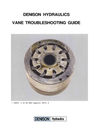
Principles of Hydraulic Circuits and Components3. By making the containers or cylinders of differentsizes, the mechanical advantage in work force in creases (Fig. 4)Figure 1A hydraulic circuit, whether it is simple or complex,uses the following basic hydraulic principles:Figure 41. A liquid can assume any shape and be bidirectional with out affecting its free flow movement(Fig 2)Basic Hydraulic Circuits andComponents Used in Turf Equipment.Although hydraulic circuit layouts may vary signifi cantly in different applications, many of the compo nents are similar in design or function. The princi ple behind most hydraulic systems is similar to thatof the basic hydraulic jack. Oil from the reservoir isdrawn past a check ball into the piston type pumpduring the pistons up-stroke (Fig 5)Figure 12. Pascal’s law states that when a confined fluid isplaced under pressure, the pressure is transmittedequally in all directions and on all faces of the con tainer. This is the principle used to extend the ramon a hydraulic cylinder (Fig 3)Figure 5Figure 32
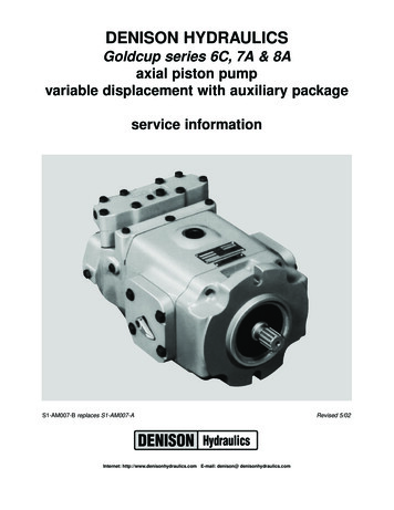
When the piston in the pump is pushed downward,oil will be directed past a second check ball into thecylinder. As the pump is actuated up and down, theincoming oil will cause the cylinder ram to extend.The lift cylinder will hold its extended position be cause the check ball is being seated by the pres sure against it from the load side of the cylinder.The cylinder will return to neutral by unseating orbypassing the check balls, allowing the oil in thecylinder to return back to the reservoir (Fig.6)Figure 7Below is a cutaway view of an actual three sectionpump.Figure 6Because the pump displacement is usually muchsmaller than the cylinder, each stroke of the pumpwill move the cylinder a very small amount. If thecylinder is required to move at a faster rate, thesurface area of the pump piston must be increasedand/or the rate which the pump is actuated must beincreased. OIL FLOW GIVES THE CYLINDERRAM ITS SPEED OF MOVEMENT AND OILPRESSURE CREATES WORK FORCE.Figure 8The flow from the pump to the cylinder is controlledby a sliding spool valve which can be actuated byan electric solenoid, or a hand or foot operatedlever. The valve shown in Figure 9 is a open centervalve, meaning that the oil flow is returned to thereservoir when the valve is in the neutral position. Ifthe oil flow is stopped in the neutral position thanthe valve is a closed center valve.We can improve the efficiency and Increase theversatility of a basic circuit by adding some sophis ticated components and changing the circuit lay out. By incorporating a gear pump in place of ahand piston pump, we increase oil flow to the cylin der which will increase the actuation rate of theram.The most common type of pump is the gear pump(Fig 7). As the gears in the pump rotate, suction iscreated at the inlet port of the pump. The fluid isdrawn in to the pump and is carried in the spacesbetween the gear teeth to the discharge port of thepump. At the discharge side of the pump the gearteeth mesh together and the oil is discharged fromthe pump.Figure 93
Below is a cutaway of an actual hydraulic controlvalve (Fig 10).Figure 12Figure 10Since the fluid from a positive displacement pumpmust flow continuously whenever the pump is run ning it must have some where to go if not beingused by the actuators. If the load on the cylinderbecomes too great or if the ram bottoms out, theflow from the pump will be directed past the reliefvalve returning to the reservoir (Fig 13).Here we see have a spool valve in our simple hydraulicsystem, we can see that the valve is in the neutral posi tion and all the flow from the pump is directed back tothe reservoir.Figure 11If the spool is moved upward, the oil flow from thepump is directed through the spool to one end ofthe lift cylinder. The oil in the opposite end of thecylinder is pushed out as the ram extends, and willpass through the spool and return to the reservoir.(Fig 12).Figure 13Substituting the lift cylinder with a gear motor, wecan now utilize out basic circuit to create rotationalmovement to drive attachments (Fig 14).Figure 144
Figure 15 shows a hydraulic reel motor.solenoid valves and the internal porting to makethe valve operate (Fig 18). The outer ports on thevalve body are threaded to allow hoses and lines tobe connected to the valve body. Care should betaken when tightening the hose and line fittings sothe valve is not distorted by over tightening of theconnections. Tighten the line and hose connectionsto the correct Flats From Finger Tight (F.F.F.T.)spec. listed in the service manual.Figure 15Figure 16 illustrates the basic circuit and compo nents necessary to drive the reel cutting units. Withthe spool in the upward position, the oil flow is di rected through the spool valve to the lower portdriving the motor in the forward direction.Figure 18The electric solenoid valve operates by supplyingelectrical current to a coil magnet, the magneticfield moves a valve spool and this directs the oil.The thing to remember is that the only differencebetween a hydraulic\electric valve, and a regularhydraulic valve is the way that the spool is moved.Figure 16Actuating the spool to the down position, the flow ofoil from the pump is directed to the opposite port ofthe motor. The motor than rotates in the reverse di rection (Fig 17).Figure 19The solenoid valves consist of the valve cartridgeand the solenoid coil (Fig 19). To disassemble thevalve remove the coil assembly and then carefullyunscrew the valve body. The O-rings and sealsshould be replaced whenever a valve body is re moved or replaced.Figure 17Another type of valve system becoming popular inturf equipment is the electric solenoid type valvesystem. The solenoid valve system consists of amachined valve body. This valve body contains the5
Figure 20Figure 22Inside the cartridge valve there is the valve spool,the armature and the armature spring. The manu facturing tolerances are extremely close and greatcare should be used when cleaning this type ofvalve. Cartridge valves used in most Toro equip ment should not be disassembled. Figure 20 is forillustrative purposes only. The best way to clean thecartridge valve is to submerge the valve in cleanmineral sprits and use a probe to push the internalspool in and out 20 to 30 times to flush out thecontamination. Mineral sprits does not affect the O ring material.Figure 23 shows the actual hydraulic circuit for aGreensmaster 3000. This circuit and componentsare used to drive the unit in the No.1 traction posi tion. When the engine is started, the pump drawsoil from the reservoir through the suction lines. Oilfrom the No.4 section of the pump passes throughthe fitting in the No.4 spool valve into the valve.The traction lever, when located in the No.1 posi tion, moves the spool so oil is directed to flow intothe No.5 metering valve section. When the tractionpedal is pushed forward oil flows out the lines at therear of the metering valve section to each motor todrive the motors. Low pressure oil returns throughthe valve and the main return line, through the filterto the reservoir.Figure 21Understanding the basic hydraulic systems andcomponents can be of great value when trouble shooting and testing hydraulic equipment. Most hy draulic systems will be similar to one of these twobasic systems (Fig 22).Figure 23The more sophisticated a hydraulic system be comes, the greater the importance of separatingthe system into individual circuits when diagnosinga hydraulic problem.6
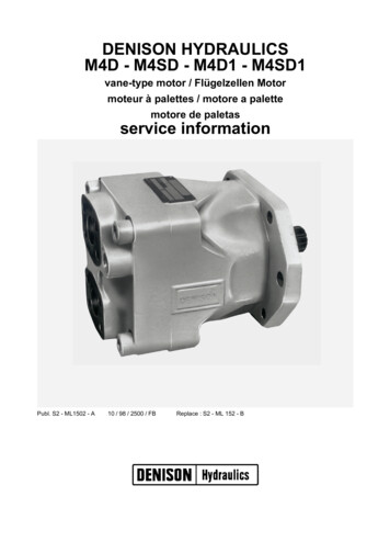
Introduction To Hydraulic SchematicsAccurate diagrams of hydraulic circuits are essen tial to the technician who must repair it. The dia gram shows how the components will interact. Itshows the technician how it works, what each com ponent should be doing and where the oil should begoing, so that he can diagnose and repair the sys tem.CIRCUIT DIAGRAMSThere are two types of circuit diagrams.A: Cutaway Circuit Diagrams show the internalconstruction of the components as well as the oilflow paths. By using colors, shades or various pat terns in the lines and passages, they are able toshow many different conditions of pressure andflow (Fig 1).Figure 21. Schematic symbol systemsA: I.S.O International Standards Organization.B: A.N.S.I. American National Standards InstituteC: A.S.A American Standards AssociationD: J.I.C. Joint Industry ConferenceA combination of these symbols are shown in thismanual. There are difference between the systemsbut there is enough similarity so that if you under stand the symbols in this manual you will be able tointerpret other symbols as well.2. Hydraulic reservoirsABCFigure 1Figure 3Reservoirs (Fig 3) are pictured as either an opensquare meaning it is a vented reservoir, or a closedreservoir meaning that it is a pressurized reservoir.Every system reservoir has at least two lines con nected to it, and some have many more. Often thecomponents that are connected to it are spread allover the schematic. Rather than having a lot ofconfusing lines all over the schematic, it is custom ary to draw individual reservoir symbols close tothe component. Similar to the ground symbol insome wiring schematics. The reservoir is usuallythe only component to be pictured more than once.B:Schematic Circuit Diagrams are usuallypreferred for troubleshooting because of their abilityto show current and potential system functions. Aschematic diagram is made up of consistentgeometric symbols for the components and theircontrols and connections (Fig 2).7
3. Lines5. Hydraulic motorsFigure 7LINESHydraulic motor symbols (Fig 7) are circles with tri angles, but opposite of a hydraulic pump, the tri angle points inward to show the oil flows in to themotor. One triangle is used for a non-reversiblemotor and two triangles are used for a reversiblemotor. An arrow through a motor shows that it is avariable speed motor.Figure 4A hydraulic line, tube, hose or any conductor thatcarries the liquid between components is shown asa line. Some lines have arrows to show direction ofoil flow, and lines may be shown as dashed lines toshow certain types of oil flow.6. Check valvesFigure 8A check valve (Fig 8) is shown as a ball in a Vseat. When oil pressure is applied to the left side ofthe ball, the ball is forced into the V and no oil canflow. When oil pressure is applied to the right sideof the ball, the ball moves away from the seat andoil can flow past it. A by-pass check is a one wayvalve with a spring on the ball end of the symbol.This shows that pressurized oil must overcome thespring pressure before the ball will unseat.Figure 5There are lines that cross other lines (Fig 5) but arenot connected, there are several ways to show linesthat are not connected. Lines that are connectedare shown with a dot or sometime just as two linescrossing. If the schematic shows a specific symbolto show lines that are not connected then anythingelse is connected.7. Relief valves4. Hydraulic pumpsFigure 9A relief valve (Fig 9) is shown as a normally closedvalve with one port connected to the pressure lineand the other line connected to the reservoir. Theflow direction arrow points away from the pressureline and toward the reservoir. When pressure in thesystem overcomes the valve spring, pressure is di rected through the valve to the reservoir.Figure 6There are many basic pump designs. (Fig 6) A sim ple fixed displacement pump is shown as a circlewith a triangle that is pointing outward. The trianglepoints in the direction that the oil will flow. If thepump is reversible or is designed to pump in eitherdirection, it will have two triangles in it and they willpoint opposite of each other indicating that oil mayflow in both directions.8
8. Hydraulic valves10. Hydraulic CylindersFigure 10A control valve (Fig 10) has envelopes (squares)that represent the valve spool positions. There is aseparate envelope for each valve position andwithin these envelopes there are arrows showingthe flow paths then the valve is shifted to that posi tion. All the port connections are drawn to the enve lope that shows the neutral position of the valve.We can mentally visualize the function of the valvein any position. A valve that has parallel linesdrawn outside of the valve envelopes shows thatthis va
Introduction To Hydraulic Schematics. Accurate diagrams of hydraulic circuits are essen tial to the technician who must repair it. The dia gram shows how the components will interact. It shows the technician how it works, what each com ponent should be doing and where the oil should be going, so that he can diagnose and repair the sys tem.