Transcription
Fuller AutoShift/UltraShift TransmissionsMore time on the road Gen3 ElectricalWiring SchematicsFuller AutoShift/UltraShift TransmissionsRRMT0010October 2007
This page intentionally left blank.
Table of ContentsTable of ContentsUltraShift DM3 6-Speed Wiring Diagram with Push Button Shifter . 3UltraShift AW3 6-Speed Wiring Diagram with Analog Shifter . 5UltraShift AW3 6-Speed Wiring Diagram with Push Button Shifter . 7AutoShift 10-Speed Wiring Diagram with Analog Shifter . 9AutoShift 10-Speed Wiring Diagram with Push Button Shifter . 11UltraShift 10-Speed Wiring Diagram with Analog Shifter . 13UltraShift 10-Speed Wiring Diagram with Push Button Shifter . 15UltraShift 13-Speed Wiring Diagram with Analog Shifter . 17UltraShift 13-Speed Wiring Diagram with Push Button Shifter . 19AutoShift 18-Speed Wiring Diagram with Analog Shifter . 21AutoShift 18-Speed Wiring Diagram with Push Button Shifter . 23Table of ContentsUltraShift DM3 6-Speed Wiring Diagram with Analog Shifter . 1
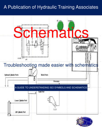
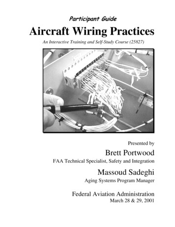
UltraShift DM3 6-Speed WiringDiagram with Analog ShifterUltraShift DM3 6-Speed Wiring Diagram with Analog Shifter30 AMP fuseTransmission ECUBattery power(Non-switched power)run to starter or BatteryOEMFor TransmissionDiagnostics181920101112BACDRail selectsensorABCGear selectsensorABC78TerminatingresistorABInput shaftspeed sensor2324ABVehicle Interface LegendOutput shaftspeed sensorBCA4-way173125335ABB - Service Bat. C - Service Bat. A - Service Ignition Inertia brakeRail selectmotor35373638Gear ectricshifterAll OEM responsible wiring shown is "typical". Consult specific application.(38) 12 volt non-switched from battery(35) 12 volt switched from ignition switch(26) Latch into the ECU(15, 16, 17, 10, 11, 3, 2, 1) Communication from and to the TECU(36, 25) Signal returns, grounds, and general OEM wiring(4, 21) -12 volt relay source(22, 32) 12 volt relay source(31) 12 volt switched from TECU(23) Signal from TECU(20) Signal into the TECU
UltraShift DM3 6-Speed WiringDiagram with Analog Shifter6 5 76 5 7For TransmissionDiagnostics perSAE StandardDimmer control inputBack sideof gaugesDash lights10 AMP 12 volt onlymanual resettingcircuit breakerorDEJ-1939 High25311516172335101126324222120UltraShift DM3 6-SpeedWiring Diagram withAnalog Shifter3 4 1 8 23 4 1 8 2FCAIgnition Key SwitchRuns to main power lead thatfeeds the ignition bus (OEMresponsible for overcurrentprotection on this line)10 AMP fuseJ-1939 Low 12 voltsbatteryBJGHCDBFGAJ-1587 data link9-wayRun tostarter solenoid30Bulkhead connectorlocated at firewallIgnitionInterruptrelay86858787a* Run to ignitioninput on EngineECMEngine Power RelayFused 10 AMP 12 voltmanual resettingcircuit breakerorJ-1939/11 data link(OEM supplied) Shieldtermination30878685StartenablerelayVehicle Interface LegendEngine ECM10 AMPfuseRun to startsignal fromigntion switchAll OEM responsible wiring shown is "typical". Consult specific application.(35, 30, 87, 87a) 12 volt switched from ignition switch(26-87) Latch into the ECU(15-1, 16-8, 17-2, 10-F, 11-G) Communication from and to the TECU(25-3) Signal returns, grounds, and general OEM wiring(4-85, 21-85) -12 volt relay source(22-86, 32-86) 12 volt relay source(31-4) 12 volt switched from TECU(23-6) Signal from TECU(20-87) Signal into TECUTerminatingresistorGND2
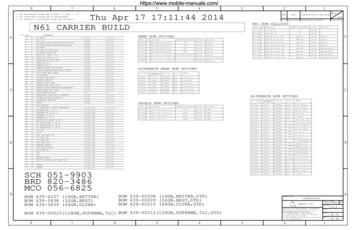
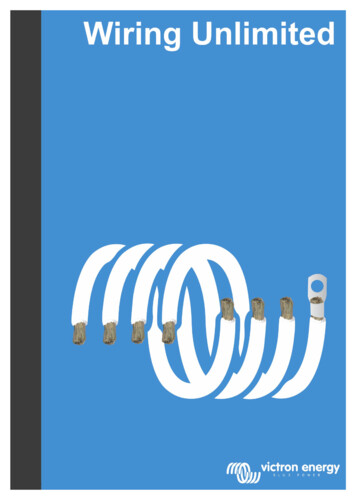
UltraShift DM3 6-Speed WiringDiagram with Push Button ShifterUltraShift DM3 6-Speed Wiring Diagram with Push Button Shifter30 AMP fuseTransmission ECUBattery power(Non-switched power)run to starter or BatteryOEMFor TransmissionDiagnostics181920101112BACDRail selectsensorABCGear selectsensorABC78TerminatingresistorABInput shaftspeed sensor2324AVehcile Interface LegendBAll OEM responsible wiring shown is "typical". Consult specific application.(38) 12 volt non-switched from battery(35) 12 volt switched from ignition switch(26) Latch into the ECU(27, 28, 10, 11, 3, 2, 1) Communication from and to the TECU(36, 25) Signal returns, grounds, and general OEM wiring(4, 21) -12 volt relay source(22, 32) 12 volt relay source(31) 12 volt switched from TECU(20) Signal into the TECUOutput shaftspeed sensorBCA4-way173125335ABB - Service Bat. C - Service Bat. A - Service Ignition Inertia brakeRail selectmotor35373638Gear icshifter
UltraShift DM3 6-Speed WiringDiagram with Push Button ShifterUltraShift DM3 6-SpeedWiring Diagram with PushButton ShifterPush Button Shift ControlPush Button Control30-way connectorF2F1 J3C1B3Dimmer control inputFor TransmissionDiagnostics perSAE StandardBack sideof gaugesDash lightsJ-1939 High10 AMP 12 volt onlymanual resettingcircuit breaker2728253135101126324222120orIgnition Key SwitchRuns to main power lead thatfeeds the ignition bus (OEMresponsible for overcurrentprotection on this line)10 AMP fuseIgnitionInterruptrelay86858787a* Run to ignitioninput on EngineECMEngine Power RelayFused 10 AMP 12 voltmanual resettingcircuit breakeror10 AMPfuseCAJ-1939 Low 12 voltsbatteryBJG30Bulkhead connectorlocated at firewallDEFHCDBFGAJ-1587 data link9-wayRun tostarter solenoidRun to startsignal fromigntion switch30878685StartenablerelayVehicle Interface LegendEngine ECMAll OEM responsible wiring shown is "typical". Consult specific application.(35, 30, 87, 87a) 12 volt switched from ignition switch(26-87) Latch into the ECU(27-F2, 28-F1, 10-F, 11-G) Communication from and to the TECU(25-J3) Signal returns, grounds, and general OEM wiring(4-85, 21-85) -12 volt relay source(22-86, 32-86) 12 volt relay source(31-C1) 12 volt switched from TECU(20-87) Signal into TECUJ-1939/11 data link(OEM supplied) ShieldterminationTerminatingresistorGND4
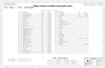
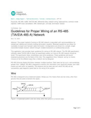
UltraShift AW3 6-Speed WiringDiagram with Analog ShifterUltraShift AW3 6-Speed Wiring Diagram with Analog Shifter30 AMP fuseTransmission ECUBattery power(Non-switched power)run to starter or 21Rail selectsensorABCGear selectsensorABC78ABInput shaftspeed sensorFor tput shaftspeed sensorBACDVehicle Interface Legend335BCA4-wayB - Service Bat. C - Service Bat. A - Service Ignition ABInertia brake173125231314Hydraulic manifoldAssemblyRail selectmotor35373638Gear selectmotor5ElectricshifterAll OEM responsible wiring shown is "typical". Consult specific application.(38) 12 volt non-switched from battery(35) 12 volt switched from ignition switch(26) Latch into the ECU(15, 16, 17, 10, 11, 3, 2, 1) Communication from and to the TECU(36, 25) Signal returns, grounds, and general OEM wiring(4) -12 volt relay source(32) 12 volt relay source(31) 12 volt switched from TECU(23) Signal from TECU
UltraShift AW3 6-Speed WiringDiagram with Analog ShifterUltraShift AW3 6-SpeedWiring Diagram withAnalog Shifter3 4 1 8 23 4 1 8 2Dimmer control input6 5 76 5 725311516172335101126324J-1939 HighBack sideof gaugesDash lightsTransmissionECU Connector Pins10 AMP 12 volt onlymanual resettingcircuit breakeror10 AMPfuseFor transmissionDiagnostics perSAE StandardFIgnition Key SwitchRuns to main power lead thatfeeds the ignition bus (OEMresponsible for overcurrentprotection on this line)DEJ-1939 LowCABJG 12 voltsBatteryHCDBFGAJ-1587 data link9-wayRun tostarter solenoidBulkhead connectorlocated at firewallRun to startsignal fromigntion switch30878685Vehicle Interface LegendEngine ECMJ-1939/11 data link(OEM supplied) orAll OEM responsible wiring shown is "typical". Consult specific application.(35, 30, 87) 12 volt switched from ignition switch(26-87) Latch into the ECU(15-1, 16-8, 17-2, 10-F, 11-G) Communication from and to the TECU(25-3) Signal returns, grounds, and general OEM wiring(4-85) -12 volt relay source(32-86) 12 volt relay source(31-4) 12 volt switched from TECU(23-6) Signal from TECUGND6
UltraShift AW3 6-Speed WiringDiagram with Push Button ShifterUltraShift AW3 6-Speed Wiring Diagram with Push Button Shifter30 AMP fuseTransmission ECUBattery power(Non-switched power)run to starter or BatteryBulkhead connectorlocated at firewallOEM181920101112BCACDGear selectsensorABCABInput shaftspeed sensor2324BRail selectsensorA78For TransmissionDiagnosticsATerminatingresistorBOutput shaftspeed sensorVehicle Interface Legend335BCA4-wayB - Service Bat. C - Service Bat. A - Service Ignition AB173125Inertia brakeAll OEM responsible wiring shown is "typical". Consult specific application.(38) 12 volt non-switched from battery(35) 12 volt switched from ignition switch(26) Latch into the ECU(27, 28, 10, 11, 3, 2, 1) Communication from and to the TECU(36, 25) Signal returns, grounds, and general OEM wiring(4) -12 volt relay source(32) 12 volt relay source(31) 12 volt switched from TECU231314Hydraulic manifoldAssemblyRail selectmotor35373638Gear ter
UltraShift AW3 6-Speed WiringDiagram with Push Button ShifterUltraShift AW3 6-SpeedWiring Diagram with PushButton ShifterPush Button Shift ControlPush Button Control30-way connectorF2F1 J3C1For transmissionDiagnostics perSAE StandardDimmer control inputBack sideof gaugesB3J-1939 HighTransmissionECU Connector Pins10 AMP 12 volt onlymanual resetting or10 AMPcircuit breakerfuse2728253135101126324Ignition Key SwitchRuns to main power lead thatfeeds the ignition bus (OEMresponsible for overcurrentprotection on this line)CABJGJ-1939 Low 12 voltsBatteryDEFHFCDBFGAJ-1587 data link9-wayRun tostarter solenoidBulkhead connectorlocated at firewallRun to startsignal fromigntion switch30878685Vehicle Interface LegendEngine ECMAll OEM responsible wiring shown is "typical". Consult specific application.(35, 30, 87) 12 volt switched from ignition switch(26-87) Latch into the ECU(27-F2, 28-F1, 10-F, 11-G) Communication from and to the TECU(25-J3) Signal returns, grounds, and general OEM wiring(4-85) -12 volt relay source(32-86) 12 volt relay source(31-C1) 12 volt switched from TECUJ-1939/11 data link(OEM supplied) orGND8
AutoShift 10-Speed WiringDiagram with Analog ShifterAutoShift 10-Speed Wiring Diagram with Analog Shifter30 AMP fuseTransmission ECUBattery power(Non-switched power)run to starter or BatteryOEM181920101112BCCAB1516ACDInput shaftspeed sensorAB2324BABVehicle Interface LegendMain shaftspeed sensorOutput shaftspeed sensor63428BCACBA1731254-wayB - Service Bat. C - Service Bat. A - Service Ignition Rail selectmotor35373638Gear selectmotor9TerminatingresistorGear selectsensorB78For TransmissionDiagnosticsRail icshifterRangevalveAll OEM responsible wiring shown is "typical". Consult specific application.(38) 12 volt non-switched from battery(35) 12 volt switched from ignition switch(26) Latch into the ECU(15, 16, 17, 10, 11, 3, 2, 1) Communication from and to the TECU(36, 25) Signal returns, grounds, and general OEM wiring(4) -12 volt relay source(32) 12 volt relay source(31) 12 volt switched from TECU(23) Signal from TECU
AutoShift 10-Speed WiringDiagram with Analog ShifterAutoShift 10-Speed WiringDiagram with AnalogShifter3 4 1 8 23 4 1 8 2Dimmer control input6 5 76 5 725311516172335101126324J-1939 HighBack sideof gaugesDash lightsTransmissionECU Connector Pins10 AMP 12 volt onlymanual resettingcircuit breakeror10 AMPfuseFor transmissionDiagnostics perSAE StandardFIgnition Key SwitchRuns to main power lead thatfeeds the ignition bus (OEMresponsible for overcurrentprotection on this line)DEJ-1939 LowCABJG 12 voltsBatteryHCDBFGAJ-1587 data link9-wayRun tostarter solenoidBulkhead connectorlocated at firewallRun to startsignal fromigntion switch30878685Vehicle Interface LegendEngine ECMJ-1939/11 data link(OEM supplied) orAll OEM responsible wiring shown is "typical". Consult specific application.(35, 30, 87) 12 volt switched from ignition switch(26-87) Latch into the ECU(15-1, 16-8, 17-2, 10-F, 11-G) Communication from and to the TECU(25-3) Signal returns, grounds, and general OEM wiring(4-85) -12 volt relay source(32-86) 12 volt relay source(31-4) 12 volt switched from TECU(23-6) Signal from TECUGND10
AutoShift 10-Speed WiringDiagram with Push Button ShifterAutoShift 10-Speed Wiring Diagram with Push Button Shifter30 AMP fuseTransmission ECUBattery power(Non-switched power)run to starter or BatteryOEM181920101112BCCACDB1516Input shaftspeed sensorABABVehicle Interface LegendMain shaftspeed sensorOutput shaftspeed sensor63428BCACBA1731254-wayB - Service Bat. C - Service Bat. A - Service Ignition Rail selectmotor35373638Gear selectmotor11TerminatingresistorA2324BGear selectsensorB78For TransmissionDiagnosticsRail ifterRangevalveAll OEM responsible wiring shown is "typical". Con
AutoShift 18-Speed Wiring Diagram with Analog Shifter . 21 AutoShift 18-Speed Wiring Diagram with Push Button Shifter . 23. 1 UltraShift DM3 6-Speed Wiring Diagram with Analog Shifter UltraShift DM3 6-Speed Wiring Diagram with Analog Shifter Gear select motor Rail select motor Electric shifter A B A B Rail select sensor Gea r10 select sensor Input shaft speed sensor Output shaft speed .