Transcription
A Publication of Hydraulic Training AssociatesSchematicsTroubleshooting made easier with schematicsA GUIDE TO UNDERSTANDING ISO SYMBOLS AND SCHEMATICS
SCHEMATICSThe mystery of them allBeing able to troubleshoot any systemwithout actually being on site can onlyhappen if you understand how to read aschematic. Many resist picking up theschematic because of their lack ofunderstanding the language of thesymbols.By understanding the symbols andfollowing the flow path of the schematic,success in determining a problem withyour system becomes quicker and morerewarding. The ability to determine apoint of entry for removal of componentsor installation of gauges and or flowmeters becomes quicker.By reading a schematic and following itsflow path, there is a less likely chance ofcomponents being removed pre-maturelythus saving time and component costs.
ISO SYMBOLSShapes and linesSymbols are critical for technical communication. Theyare not dependent on any specific language, beinginternational in scope and character. Hydraulic graphicsymbols emphasize the function and methods ofoperation of the components. These symbols can berather simple to draw, if the logic and elementary formsused in symbol design are understood.The elementary forms of symbols are: Circles Squares Triangles Arcs Arrow Dots Crosses
READING ASCHEMATICNot for the faint of heartA schematic is a compilation of interconnected graphicsymbols, showing a sequence of operational flow. In short,they explain how a circuit functions. Correct schematicreading is the most important element of hydraulictroubleshooting. Although initially most circuits mayappear complicated, recognizing standard symbols andsystematic flow tracings simplifies the process.
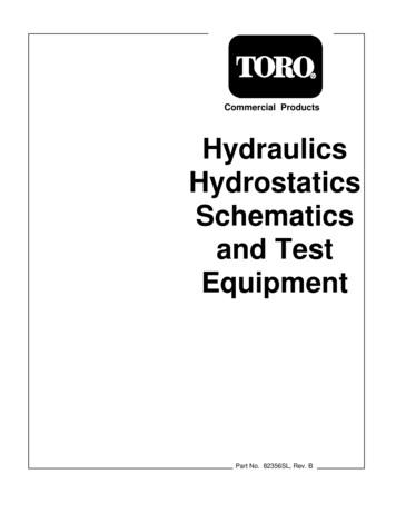
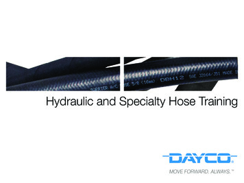
READING A SCHEMATICThis circuit uses two sequence valves. Theyare normally closed valves that open at apredetermined setting. By tracing the flowin the circuit, on should be able todetermine how the circuit is designed tooperate. This process is called reading aschematic.Tracing the flow in this circuit reveals that it isdesigned to keep retracting and extendingautomatically when the prime mover is engaged.Once the circuit is understood, proper function ofthe system will depend on the proper setting andfunction of the sequence valves and the properfunction of the hydraulically piloted directionalcontrol valve.
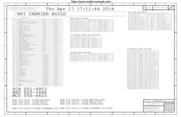
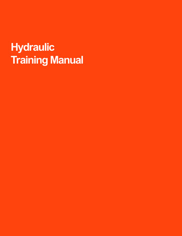
PROPER SCHEMATICDESIGNBuilding a schematic isimportant for all who are toread it and be able totroubleshoot with it. Here wewill examine wrong and rightways of schematic usage.Too often in industrialmanufacturing properschematics are not suppliedto the owners of theequipment. This makes itvery difficult to understandhow the system is toproperly operate.Excluding the hand writtennotes and numbers that weadded, this is a customersschematic whomanufactured a proto-typeminiature F16 planes for theAir Force Recruiters. Thisschematic was handed meand asked me totroubleshoot the system.What would you see as beingthe first problem with this?There is no way of knowing whatthe pathways were for the valves.The flow paths are missing in thecomponents.
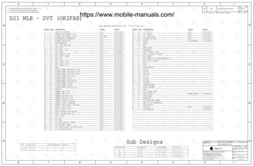
PROPER SCHEMATICDESIGNThis customer wanted this system troubleshoot as to why they broke off theback cover plate on the steering pump. Looking at this schematic, even thenovice troubleshooter can determine that this is not a good format.What is wrong with this picture?In this particular system the customer just replaced all the hoses in thesystem and this is the factory supplied page which informs the customerwhere the hoses are to be installed. Though this is a good parts page, it isalso the page in the book the helps the mechanic or operator determinewhere the components are located and how they interact with each other.The inserting of the number bubbles confuses the one wishing totroubleshoot.
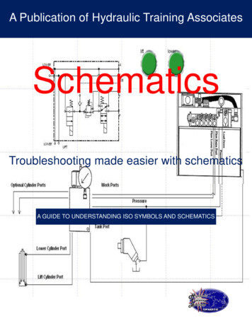
PROPER SCHEMATICDESIGNBelow is the re-drawn schematic that the customer can now use fortroubleshooting. The flow path can be followed and understanding of whatthe components do help assist in determining what caused the failure. Byfollowing the flow from the double fixed displacement pump we found thatafter re-installing the new hoses, they crossed the auxiliary line with thefixed steering line and when they turned the steering wheel the flow deadheaded the second pump.
TROUBLESHOOTINGIt would be a virtually impossible to try to document the causeand remedy of every possible fault that could occur on eventhe simplest hydraulic system. For this reason it is necessary toadopt a logical approach to troubleshooting, in order to locatea fault as quickly and accurately as possible.Troubleshooting can be either frustrating orrewarding.The outcome depends on how you approachthe task at hand. As in any job to be done,the best tools available will help make thejob go faster; establishing a starting point tosearch out the trouble requires knowledgeof several different orientations.As we have seen a proper schematic helps to visualize whatcomponents are involved in the system and how they areconfigured. The flow of the components settings of the pressurecontrols should all be listed on the schematic. Attempting tovisualize the hydraulic system, of any but the simplest machineand how it functions by looking at the machine first, can be selfdefeating.Many of the major hydraulic components are not visible from asingle vantage point and time can be lost simply in becomingfamiliar with the hydraulic system. This time is better spentreviewing the circuit diagram and relating the trouble symptomsto components which could be at fault.
“CSI of Troubleshooting” by J. Eric Freimuth June 2004 Fluid PowerMagazine: Ten steps in the CSI of troubleshooting.““Success is not final, failure is not fatal: it is thecourage to continue that counts.”Winston Churchill
GO TO OUR WEB SITEFOR A FREE DEMO TODAYHydraulic Training Associates provides more then just training, we can redraw your schematics and supply them to you animated and in an MP4format to use on your Smart Phones.For more information on this and much more call today: 866-432-9771www.htahydraulics.comContact our office for classes in your area
These symbols can be rather simple to draw, if the logic and elementary forms used in symbol design are understood. The elementary forms of symbols are: Circles Squares Triangles Arcs Arrow Dots Crosses . READING A SCHEMATIC Not for the faint of heart A schematic is a compilation of interconnected graphic symbols, showing a sequence of operational flow. In short .