Transcription
Professional LocksmithStudy Unit 4Lock MechanismsThis sneak preview of your study material has beenprepared in advance of the book's actual online release.
iiiPreviewWelcome to Study Unit 4 of your Professional Locksmith course! In your last studyunit, you learned all about keys and how to identify them. Now, in this study unit,you’ll begin learning about lock mechanisms in depth. A lock mechanism is the internalassembly of a lock that makes it work.You’ll be learning about a variety of lock mechanisms including key-operated, combination, and electric types. With the assistance of plenty of detailed diagrams anddrawings, you’ll be able to look at the insides of locks. You’ll discover how theselocks are constructed and how they work.Then, when you’ve gained a solid foundation of knowledge about lock mechanisms,you’ll learn what types of problems these locks are likely to have and what serviceslocksmiths will need to perform. We’ll explain how to completely disassemble and reassemble various lock mechanisms. Finally, we’ll tell you how to perform simpleservicing, cleaning, and lubrication on lock mechanisms.When you complete this study unit, you’ll be able to Name the four basic key-operated lock mechanisms Identify the basic types of key-operated lock mechanisms by visual inspection Name the principal parts of each lock type Explain, in simple language, how different types of lock mechanisms work Clean, lubricate, and perform simple maintenance on locks Disassemble and reassemble each type of lock as needed for servicing List the strong and weak points of each type of mechanism Explain how high security locks function Explain how combination entry locks work
vContentsINTRODUCTION . . . . . . . . . . . . . . . . . . . . . . . . . .1What is a Lock Mechanism?Locks vs. Lock MechanismsKEY-OPERATED LOCK MECHANISMS . . . . . . . . . . . . . .3How Key-Operated Mechanisms WorkThe Warded MechanismThe Lever Tumbler MechanismThe Disk or Wafer Tumbler MechanismThe Pin Tumbler MechanismHigh-Security Lock MechanismsInterchangeable CoresKey-Operated PadlocksCOMBINATION LOCK MECHANISMS . . . . . . . . . . . . . . 39IntroductionOperationDisassemblyCombination Entry LocksELECTRIC LOCK MECHANISMS . . . . . . . . . . . . . . . . . . 44ApplicationsOperationTHE KEY TO SUCCESS . . . . . . . . . . . . . . . . . . . . . . . 47KEY POINTS TO REMEMBER . . . . . . . . . . . . . . . . . . . . 47LOCKING IT UP! ANSWERS . . . . . . . . . . . . . . . . . . . . 53EXAMINATION . . . . . . . . . . . . . . . . . . . . . . . . . . 55COMING ATTRACTIONS . . . . . . . . . . . . . . . . . . . . . 59
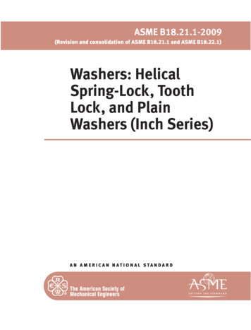
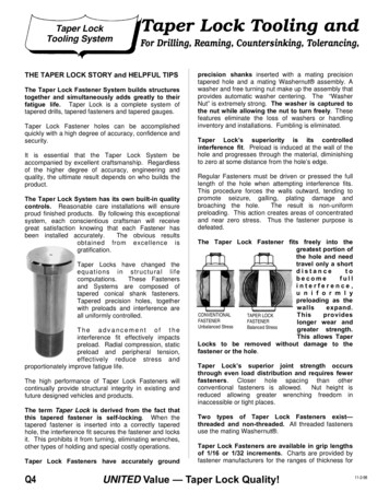
1Lock MechanismsDo You Know. . .What is the most important component of a combination lock?What are the major parts of a padlock?What is a ward?In these pages, you’ll find the answers to these and many more questions about lockmechanisms.INTRODUCTIONWhat is a Lock Mechanism?A lock mechanism is the assembly of parts inside a lock thatmakes it work. In most common locks, the locking mechanism holds or moves a latch, bolt, or shackle into the lockedor unlocked position. Due to the many types of lock designs,there are many different types of locking mechanisms.FIGURE 1—This figureshows a bolt in the“thrown” position.For example, a door lock contains a mechanism to operate alatch or bolt. The latch or bolt is the part that extends into thestrike, anchoringthe door to the doorframe. When thebolt is thrown, itmoves into thestrike and locks thedoor; when the boltis retracted backout of the strike, thedoor is free to open(Figure 1).
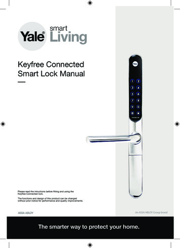
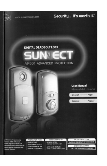
2Lock MechanismsFIGURE 2—A padlockmechanism holds theshackle inside the lockcase or shell.In contrast, a padlock contains a mechanism that holds theshackle in the case or shell of the lock, or that allows theshackle to release (Figure 2).Locks vs. Lock MechanismsIt’s important for you to note the difference between a lockand a lock mechanism. The word lock is a general term thatrefers to any device installed or attached to improve security.A padlock, a door lock, a car ignition lock—all of these arelocks. A lock mechanism is the inside structure of a lock. Forexample, a door lock could contain a warded mechanism, pintumbler mechanism, or a disk tumbler mechanism, depending on how it was made.For our study purposes, all lock mechanisms can be dividedinto three basic types: key-operated lock mechanisms, combinationlock mechanisms, and electric lock mechanisms. In this study unit,we’ll examine each of these different mechanisms in detail.We’ll look at how they’re constructed and how they operate;then we’ll examine simple repair techniques for each type. Let’sstart by turning our attention to key-operated lock mechanisms.
Lock Mechanisms3KEY-OPERATED LOCK MECHANISMSHow Key-Operated Mechanisms WorkA key-operated lock mechanism is simply any type of lock that’sopened and closed by inserting and turning a key. (Remember,as we discussed in Study Unit 2, not all locks are opened by akey. Some locks are opened by dialing a number combination,and some contain electrically-operated switches.) However,key-operated locks are the most common and familiar to us.Key-operated locks are found in residential doors, cars, andpadlocks.The four most common types of key-operated lock mechanismsare the warded mechanism, the lever tumbler mechanism, the disktumbler or wafer mechanism, and the pin tumbler mechanism. We’lldiscuss each in turn now.The Warded MechanismThe word ward means to guard or guard against; thus, we may“ward off” a cold by taking vitamin C (or a bowl of chickensoup). Similarly, a warden is a prison guard. In locksmithingterms, a ward is a metal barrier inside a lock mechanism thatprevents just any key from opening the lock. The ward ensures that only the proper key will engage the mechanismand open the lock. The “right” key contains cuts that exactlymatch the shape of the wards inside the lock.The warded lock mechanism is the oldest type still in use today (it was first used by the Romans thousands of years ago).Bit keys and barrel keys are used to open warded door andcabinet locks; flat keys are used to operate warded padlocks.The basic principle behind the warded lock is barrier protection.This means that the wards create a physical barrier that mustbe overcome before the lock can be opened. The security of thewarded mechanism comes from the type and number ofwards it contains. A ward is simply a metal ridge inside thelock that creates a barrier to the lock bolt. A properly-cut keywill fit around the wards and be free to turn, opening the lock.
4FIGURE 3—This wardedmechanism containstwo wards.FIGURE 4—Thiscomplex warded lockcontains several wardsarranged to provideextra security for thelock. Note the manycuts needed on thekey to allow it to clearthe wards.Lock MechanismsA warded lock cancontain any numberof wards. The simplest type containsonly one ward andis called a singlewarded lock. The interior of a simplewarded lock isshown in Figure 3.Note that when thekey is inserted, thecut correspondsexactly to the placement of the wards. When the proper key enters the keyhole ofthe unlocked door, negotiates the wards, and is turned, itraises the deadbolt over the obstructions that detain it. Thedeadbolt enters the strike, and the door is now effectivelylocked.KEYNow look at thelock interior shownin Figure 4. Thislock containsseveral complexwards. The key forthis lock was elaborately cut to “clear”the obstructionscaused by thewards.Some locks havewards on theWARDSexterior of theirkeyways. Thesewards are calledcase wards. Case wards add a little security to a lock, since anadditional cut must be made on a key just to allow it to slideinto the keyway (Figure 5).
Lock Mechanisms5FIGURE 5—Case wardsin the keyway of awarded lock add alittle security.A skeleton key is a key that has beenground down to make it very thin(Figure 6). The wards of a warded lockare easily bypassed using a skeletonkey. For this reason, warded locks arenot recommended in circumstanceswhere a high degree of security isdesired.Warded Mortise Locks andWarded Rim LocksThe warded door lock in Figure 7B iscalled a warded mortise lock, because itis installed in a recess in a door called amortise. By comparison, the warded rimlock in Figure 7A is surface-mounted on(rather than in) the door.Figure 8 shows the interior mechanismof a typical warded rim lock. Notethat the lock contains two bolts: aFIGURE 6—A skeletonkey-operated deadbolt and a latch bolt.key is designed tobypass the wards inThe latch is operated by turning thedoor-knob. The latch fits securely into a a warded lock.strike, the metal plate recessed in thedoor jamb. When the latch is in place,the door will be held closed, but not locked,since no key is required to move it. When the inside latch
6Lock MechanismsFIGURE 7—Part A of thisillustration shows awarded rim lock; Part Bshows a wardedmortise lock.button is pressed down, though, it does prevent the latch boltfrom being released by anyone outside the door. The deadboltis operated by a key or by turning a turnpiece inside thedoor. The door is truly locked when the deadbolt is thrown.INSIDELATCH SPRINGINSIDELATCH H BOLTSPRINGFIGURE 8—Interior of aWarded Rim LockKEY HOLE
Lock Mechanisms7Advantages and Disadvantages of the Warded LockWarded locks aren’t generally used on today’s exterior doors.They have been replaced by pin tumbler or disk tumbler locksin most cases. This is because warded locks aren’t nearly as secure as pin tumbler locks (which we’ll discuss shortly).Why isn’t the warded lock secure enough? Well, a lock’ssecurity depends on the following two things:1. The complexity of its internal mechanism2. The ease of looking into the lock to see the mechanismIn both of these cases, the warded lock offers little protection.Its mechanism is simple and the keyhole is large enough toview most of the inside of the lock. Because the keyway is solarge, it’s very simple to look inside the lock, bypass thewards with a pick, and release the locking mechanism todisengage the latch or bolt and open the door.The simplest method of picking a warded lock is to use a pickkey. Several pick keys for warded locks are illustrated inFigure 9. A pick key is a specially ground and cut piece offlat steel that will fit into thekeyway of a lock. A smallcurved projection is left near thetip of the key pick. The remainder of the key pick is quite narrow. A pick key will open allbut a few warded lock types.As you can see by the varietyof ward cuts on these pickkeys, it’s a simple matter toselect a pick key and turn itgently in the lock. If you feel aninternal ward interfering withthe pick key, you simply stopand try another pick key.FIGURE 9—Key pickslike the ones shownhere are useful foropening warded locks.However, despite the relativelack of security in wardedlocks, note that there are circumstances when the simplicity of the warded lock is an
8Lock Mechanismsadvantage. For example, warded padlocks are a good choicefor use in wet, sandy, or dusty environments where a morecomplex lock would rust or jam easily.Cleaning, Lubrication, and Repair of Warded LocksOften, a warded lock will stop working, or will work onlywith difficulty. Note that while it’s usually easier andcheaper to replace a warded lock than repair it, a customermay want an old lock repaired anyway. This is especiallytrue in very old homes where the owner may want to keepthe warded lock for its “quaint” appearance.You may also be called upon to repair small warded locks inantique furniture (chests, cabinets, clocks, trunks, and so on).One good suggestion is to keep any old lock parts and anyold bit and barrel keys you can find (at junk shops, yardsales, and so on). Since these parts and keys aren’t widelymanufactured anymore, keep them on hand for repairs.One of the most common causes of warded lock failure is thebuildup of dust and debris inside the lock. Paint is one of thebiggest offenders. Repeated painting of a door over the yearscan leave a warded lock clogged and can make it impossibleto insert or turn the key.In such a case, you’ll need to open up the lock to clean it,lubricate it, or replace worn parts. The warded lock is theeasiest to disassemble of all the lock types we’ll look at. Simply remove the screws on the cover plate, and the “guts” areexposed. After removing the cover plate, replace any rustedor worn parts. Then, use a wire brush to clean dirt and oldpaint away from the affected lock parts. Unless absolutely necessary, stay away from commercial paint removers: they tendto attract lint after use.Next, use a commercial lubricant such as WD-40 (never oil;we’ll explain why later) to lubricate the lock. You can apply itusing the spray assembly attached to the can.
Lock Mechanisms9Locking It Up! 1At the end of each section in your Professional Locksmith texts, you’llbe asked to pause and check your understanding of what you’ve justread by completing a Locking It Up! quiz. Writing the answers to thesequestions will help you review what you’ve studied so far. Please complete Locking It Up! 1 now.Fill in the blanks in the following statements.1. keys and keys are used to open warded door andcabinet locks.2. A is the assembly of parts inside a lock that makes it work.3. A contains a mechanism that holds or releases a shackle inthe case or shell of the lock.4. A is simply any type of lock that’s opened and closed by inserting and turning a key.5. The word means to guard or guard against.6. Wards on the exterior of the keyway of a lock are called .7. A is a key that has been ground down to bypass the wardsin a warded lock.8. A lock is mounted on the surface of a door.Check your answers with those on page 53.
10Lock MechanismsThe Lever Tumbler MechanismFigure 10 shows an exterior view of a typical lever tumbler lock.Lever tumbler locks are used on school lockers, cash boxes,suitcases, mailboxes, and safe-deposit boxes. The slim, flat design of the lever tumbler lock is more appropriate for these applications than a cylinder-type lock. Modern lever tumbler locksalmost always use flat keys, although some European models areoperated with bit or barrel keys. The average lever lock is onlyslightly more secure than the warded lock; however, the leverlocks used on safe deposit boxes are very secure.FIGURE 10—A LeverTumbler LockLever tumbler locksare available in awide range ofsecurity levels.Generally, the levertumbler locks youwill encounter willhave between twoand five lever tumblers within thelock. Some highsecurity lever tumbler locks can haveas many as sixteen lever tumblers. (The more tumblers, themore difficult it is to invade the lock.) High-security levertumbler locks are used on some types of bank safe depositboxes and on some types of public lockers. In this section onpicking lever tumbler locks, we’ll look at the medium security lever tumbler locks with two to five lever tumblers.Now, let’s look at the interior of a lever tumbler mechanism(Figure 11) to see how it operates. This lock mechanismcontains three lever tumblers. Regardless of the number oftumblers, however, the operation is essentially the same in alllever tumbler locks.Each lever tumbler is a flat metal plate held in place by springpressure. Figure 12 shows the parts of one lever tumbler.Taking a close look at these parts will help you understandhow the lever tumbler lock operates. The lever is the mostimportant part of the lever lock mechanism, since its movement controls the movement of the bolt. Other importantcomponents of the lever tumbler lock are the gate, the post,and the saddle.
Lock Mechanisms11FIGURE 11—This figureshows the interior of alever tumbler lockmechanism.COVER BOSSCOVERTRUNNIONLEVER TUMBLER(TOP)LEVER TUMBLER(MIDDLE)BOLTNOTCHLEVER TUMBLER(BOTTOM)POSTBOLTBASEThe key enters through the cover boss and trunnion. When thekey is inserted, the key’s cuts will engage the saddle of eachlever tumbler. The saddle must be raised enough to allow thepost that is attached to the bolt to slide into the rear trap.When this action occurs, the bolt will slide out of the jamb ofthe door, opening the door.In some lever tumbler locks, you may see different coloredlevers. The color of the lever will identify the trap-to-saddledistance. Also, in some lever tumbler locks, the levers themselves will be of different thicknesses. Here the thicker thelever the greater the distance is between the bottom of thesaddle and the center of the trap.
12Lock MechanismsFIGURE 12—Thisillustration shows theparts of one levertumbler.Disassembly and ServicingLever tumbler locks that have been riveted or spot-weldedare generally very inexpensive, and aren’t worth the workrequired to disassemble and reassemble them. Instead, theyshould just be replaced. Other types of lever locks can beopened either by removing the cover screws or by prying thecover off, according to how the cover is attached. Carefullyremove the trunnion, and then the lever tumblers in order.Reassemble by reversing the procedure.Once the lever tumblers have been removed, the exposedbase and bolt can be checked for irregularities. If you findany foreign matter, remove it.The most probable cause of trouble in a lever tumbler lock isa broken spring. To correct, remove the broken spring fromthe affected lever and replace it.The Disk or Wafer Tumbler MechanismThe disk tumbler mechanism (also called the wafer tumblermechanism) is commonly used in automobile doors, desks andcabinets, and vending machines. Disk tumbler locks providemuch better security than warded or lever tumbler locks. Notethat while most disk locks are constructed the same way, their
Lock Mechanisms13outward appearances may vary depending on whatthe lock is used for.Figure 13 shows afamiliar example ofa disk tumbler lock.FIGURE 13—This type ofdisk tumbler lock iscommonly used ondesks.Figure 14 is an exploded drawing ofthe principal partsof a disk tumblerlock. The main components of a disk tumbler lock are the shell,the plug, the disks, and the springs. Let’s examine the disks first.FIGURE 14—ExplodedView of a Disk TumblerLock YSPRINGPLUGDISKSSPRINGSSPRINGSWhen you first think about a disk tumbler or wafer tumblerlock, you may think that the disks within the lock are circular. However, this is not the case. The disks or wafers insidethese locks are small, flat, rectangular pieces of steel, eachcontaining a slot or hole. The key will be inserted into theseslots to operate the lock.
14Lock MechanismsFor most disk locks, the disks come in five different slot arrangements (Figure 15). The location of the slot in each diskwill determine the key cut depth needed. In Figure 15, notethat the position of the slot in each disk is a little different.The distance from the top of each disk varies. You may alsonotice that each disk has a number stamped on it. Thisnumber identifies the type of disk you’re working with.FIGURE 15—The fivedifferent sizes of discsin a disk tumbler lockare shown here.A disk tumblerlock’s plug willcontain an arrangement of any ofthese five disks(any one of thedisks may appearmore than once, aswell). While thefive disk tumblers inside the disk tumbler lock plug are thesame height and width, the rectangular cuts in the disks varyin terms of their position on the disks. The key has five cutsthat correspond exactly to these tumbler cuts. The arrangement of the disks forms each lock’s individual combination.The plug is held inside the shell. The shell contains an upperand a lower slot. The disks or wafers inside the plug “stickout” a little and fit into the lower slot in the shell. The disksor wafers are pressed into the slot by means of small springs.This keeps the plug from turning inside the shell whenthere’s no key in the lock.FIGURE 16—Thiscutaway side viewshows a key inserted ina disk tumbler plug.The disks have beenpulled into alignmentby the key, freeing theplug to turn.The disks are slotted for key entry. When the proper key is inserted into the lock, the disks are pulled away from the slot inthe shell and centered in the plug.This action frees theLOCKING CAMplug from the shellDISKSand allows the plugto turn with the key.Figure 16 shows aview of a key inserted in a disk lock.KEYIf an improperlycut key is insertedinto the plug, oneor more of the disks
Lock Mechanisms15may not be lifted out of the slot in the shell. This action willprevent the plug from turning and the lock from opening.The Side Bar Wafer Lock MechanismA side bar wafer lock is a variation of the disk tumbler lock.Side bar wafer locks provide a greater degree of security thansimple disk tumbler locks because they’re extremely difficultto pick. Side bar wafer locks will make up a large amount ofyour locksmithing work. This is because they’re inexpensive,and also because they’re widely used for ignition, door, andtrunk or rear hatch locks for General Motors automobiles andlight trucks.The five types of wafers that you might find inside a side barwafer lock are shown in Figure 17. The disks in a side barwafer lock are much like those in a standard disk tumblerlock, but with one change: each disk (or wafer) has a Vshaped notch on one side. These wafers may be identified bya number (one through five) stamped on the wafer. Thesenumbers refer to the heights of the position of the V-shapednotch.You’ll remember from our previous discussion that a regulardisk lock opens when the disks disengage from a slot in theshell, allowing the plug to turn. In contrast, in a side barwafer lock, the disks release a side bar that disengages from aslot in the shell.FIGURE 17—This figure shows the five types of wafers or disks you’ll see inside a side bar wafer lock. Note the V-shaped notches in the sides of the wafers.
16FIGURE 18—In thiscutaway view of a sidebar wafer lock, youcan see how the disksmust be aligned toallow the side bar todisengage from theshell.Lock MechanismsWhen the side barwafer mechanism islocked, the side barextends into a special slot inside theshell; as a result, theplug is held securelyin place. As the keyenters the plug, thekey pushes the disksupward, causing theside bar to fall intothe group of Vshaped notches onthe side of thedisks. The side baris now clear of theslot, and the plug is free to turn with the key. The disks canonly be aligned by the proper key. The operation of a typicalside bar wafer arrangement is shown in Figure 18.The Cam Lock MechanismFIGURE 19—Thisillustration shows atypical cam lock.One variation of the disk tumbler mechanism is the cam lockshown in Figure 19. Cam locks are used extensively on cabinet doors and deskdrawers. In thiskind of lock, amoveable cam is attached to the rearof the lock. Thecam is a flat pieceof metal that rotates when the keyis turned in thelock. The cam creates a physical barrier that prevents a door or drawer from being pulled open.When the cam is turned into the “lock” position, the cam willhold the door or drawer in place. When the cam is turned tothe “unlock” position, the door or drawer will be free toopen.
Lock Mechanisms17DisassemblyDisk locks may need to be disassembled for cleaning, repair, orrekeying. Some disk tumbler locks are easy to take apart, othersare not; it depends on the method used to hold the plug insidethe shell. Some plugs are held with a screw-in retaining plate;others must be drilled to access the internal retaining clip.FIGURE 20—A hole hasbeen drilled in this disktumbler lock to allowaccess to the retainingclip.In the lock shown inFigure 20, a hole hasbeen drilled in theshell to allow accessto the retaining clipthat holds the plugin place. On somedisk tumbler locks,this hole may already be present.To remove the plugfrom such a lock, insert a small tool such as a lock pick or thinawl into the drilled hole. By applying pressure, the retainingclip for the plug can be compressed. With the key located in theplug, turn the plug slowly while pulling outward. The plugshould slide from the shell.Once the plug is removed, you can begin removing thedisks. The disks may lift right out, or they may need to be“pinched” to allow removal, depending on the type of lock.As each disk is removed from the lock, place it in order in apin tray or other small container. To reassemble the lock,reload the disks into the plug. Then insert the plug into theshell, applying only as much pressure as is necessary for theend of the plug to engage the retainer clip.Disassembling a Side Bar Wafer Lock. Since most side barwafer locks are found in cars, you’ll need to remove it fromthe vehicle before you can disassemble the lock itself. In general, ignition and trunk locks are removed by driving out aretaining pin to release the lock shell. In a door lock, a specialretaining clip may be used to hold the lock shell. (We’ll discuss the exact details on removing locks from automobiles ina later study unit. If you want more information now, youcan consult any automotive service manual.)To disassemble this type of lock, you will have to remove thespring and disk retainer cover. Pry upwards on the cover with
18Lock Mechanismsa small screwdriver and it will come free of the shell. (Note:Very often, this cover will be bent or distorted upon removaland require replacement after you have moved the discs.These covers are available through locksmith suppliers.)With the cover removed, begin lifting the six internal springsfrom the lock with a pair of tweezers. Place these springs inyour pin tray or other container.If you were disassembling the lock for the purpose of rekeying, you would now lift the disks out of the plug and replacethem as needed. Replace the springs and then insert a newspring retainer cover into the shell.Disassembling a Cam Lock. To disassemble a cam lock,remove the nut, lock washer, and cam from the back of thelock. The core can now be pushed out with finger pressure,or eased out using the key.Cleaning and LubricatingIf a disk or spring has broken inside a disk tumbler lock, thelock is sometimes replaced. This is because it can be cheaperto replace a malfunctioning disk tumbler lock than to repairit. However, in many cases, a thorough cleaning and lubrication can quickly and easily correct many lock problems.One of the first things to check when a disk tumbler lock fails isthe key. When a key gets very worn, it may not lift the disks tothe proper height, keeping the plug from turning. Often when akey is excessively worn, cutting a new key will correct the problem.Many disk tumbler locks fail due to dirt or lack of lubrication(particularly car locks, which are constantly exposed to theelements). Disk tumbler plugs can be cleaned in a safe andnon-flammable solvent. Spray solvents and other types ofcleaning solutions are available from locksmith supplyhouses and hardware stores. If you wish, you can also useelectrical spray cleaners such as those used on volumecontrols and other electronic components. A good cleaningsolution should flush any dirt and dust from the lock.It’s a good idea to lightly lubricate the lock with a commerciallubricant after cleaning. Never use oil, grease, or any type ofmineral- or paraffin-base lubricants. These types of lubricantswill collect dust and dirt over time, and eventually turn into apaste inside the lock. This paste will cause the lock to malfunction.
Lock Mechanisms19Locking It Up! 2Indicate whether each of the following statements is True or False.1. Modern lever tumbler locks almost always use bit keys.2. The disk tumbler mechanism is also called the wafer tumblermechanism.3. A disk tumbler lock’s springs typically contain an arrangementof five disks.4. Lever lock mechanisms are commonly used as ignition, door,and trunk or rear hatch locks for General Motors automobilesand light trucks.5. When the side bar wafer lock mechanism is locked, the sidebar extends into a special slot inside the shell; as a result, theplug is held securely in place.6. Cam locks are used extensively on home entry doors and carignitions.7. All disk tumbler locks are easy to take apart.8. It’s generally cheaper to replace a malfunctioning disktumbler lock than to repair it.9. In a disk tumbler lock, the rectangular cuts in the disks arealways in the same position.10. Disk tumbler locks are seldom used today.Check your answers with those on page 53.
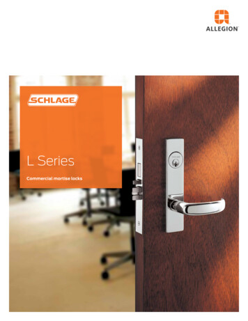
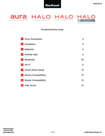
20Lock MechanismsThe Pin Tumbler MechanismThe pin tumbler lock is the most secure and widely used locktoday. This type of lock is very popular in home entry locks,padlocks, and other types of locking devices.A pin tumbler mechanism is contained within a device calleda cylinder. Pin tumbler cylinders can be installed in a varietyof products: in a door knob, in a door surface, or in a car ignition. While each of these locks functions differently from theoutside, the pin tumbler cylinder itself always works thesame way. Pin tumbler lock mechanisms are always operatedwith cylinder keys.ConstructionA pin tumbler cylinder contains the following parts: the plug,the keyway, the top pins, the bottom pins, and the springs.Let’s start our discussion by examining these parts.FIGURE 21—ExteriorView of a Pin TumblerCylinder and PlugFigure 21 shows anexterior view of apin tumbler cylinder and a plug. Thecylinder is therounded shell thatsurrounds andholds the plug,which is the centralassembly of themechanism. Theplug is a small“tube” that containsthe bottom pins(Figure 22). Notethe five holes thatwere drilled alongthe length of theplug, each containing a bottom pin.(Many pin tumblermechanisms contain five pins, butthere are six- and even seven-pin arrangements.) The keywayis the opening in the plug that allows a key to be inserted.
Lock MechanismsFIGURE 22—Plug andBottom Pins21Now look atFigure 23, whichshows an interiorview of a pin tumbler cylinder. Thevisible componentsof the pin tumblerlock are the plugand the
KEY-OPERATED LOCK MECHANISMS. How Key-Operated Mechanisms Work. A. key-operated lock mechanism. is simply any type of lock that's opened and closed by inserting and turning a key. (Remember, as we discussed in Study Unit 2, not all locks are opened by a key. Some locks are opened by dialing a number combination,