Transcription
Saflok Quantum PixelInstallation InstructionsPK3693-T - 2021 - 09EN
Saflok Quantum Pixel Installation InstructionsWARNINGCAUTIONIMPORTANTAll parts needed to install the Quantum Pixel lock are included with each unit. Please check to make sureall parts are accounted for before you begin the installation. Do not substitute any of the parts. The useof substitute parts will result in poor performance of the lock.All information contained herein, including but not limited to product pricing and other intellectualproperty, is confidential and intended for the sole use of the addressee(s) so named. Any misuse of thisconfidential information contained herein may result in legal action by dormakaba USA Inc. andits parent company.Door and door frame preparationTools required for this stepRecommend doors prepped at factory for higher precisionDo not drill both STD and ADB Ø7/16 thumb turn holes. Drill only the hole that corresponds to the mortisepurchased. Do not drill a Ø7/16 thumb turn hole for utility locks. DrillPlunge Router- 1” Straight- 1-1/16” StraightDrill bits- 11/16” Reader- 7/16” Thumb Turn- 11/64” Mortise Mounting2-1/8" Hole SawChiselJigsaw1:1 Door Prep TemplatesOptional Door Prep Jig P/N: FIXT-PIXEL (available for purchase)- Door prep jig only available for 1-3/8" [34.9mm] OR 1-3/4" [44.5mm] doors with standard centeredlower mortise pocket and no rabbet. 2021 dormakaba USA, Inc. All trademarks and registered trademarks are the property of their respective owners.2Saflok Quantum PixelPK3693 T09-21
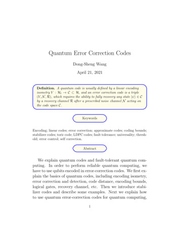
Door and door frame preparationFigure 1 - Exploded Lock ViewCONTROLLER FACE PLATE#12 X 1 PANHEAD SCREWSLOCK CONTROLLER#8-32 X 1/4 FLATHEAD SCREWSTHUMBTURN BASEFERRITE (OPTIONAL)#6 X 1/2 FLATHEAD SCREWSREADER BASETHUMBTURNANTENNA PCB#4 X 3/16 SCREWSTRIKE PLATE#6 X 1/2 FLATHEAD SCREWSREADER COVERI/S LEVER ROSESHOULDER SCREWSI/S LEVER ASSY#12 X 1-1/2#12-24 X 3/8FLAT HEAD SCREWSOR#8-32 X 1/4 FLATHEAD SCREWSMORTISE#12 X 1-1/4 PANHEAD SCREWSO/S LEVER ASSYMORTISE FACE PLATEFigure 2 - Door preperation jigSaflok Quantum PixelPK3693 T09-213
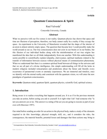
Door and door frame preparation (continued)Figure 3 - Door preperation templates.69[17.5]OUTSIDE ONLYNOT THRUDOOR EDGEVIEW1.75[44.5](.41[10.3])1.09[27.8]DOOR EDGEVIEW.23[5.9]2X R4.70[119.3].25[6.4]4LY* .4 E ONISORT UB M THR] AD NOTDOOR EDGE1.1[ 16.88[174.6]* 1.00[25.4]4* .4 E ONLYISORTD M T THRUNO] ST.1[ 112.75[69.9]BACK CKCASECL STRIKECL LOCK2.44[61.9]1.50[38.1]CLLEVER2.13[ 54.0]THRUOUTSIDEPREP1.09[27.7]INSIDEPREPADD .02 RELIEF CUTTO BOTTOM EDGE*ONLY ONE THUMB TURN HOLE TOBE DRILLED, BASED ON LOCK TYPE*NO THUMB TURN HOLE FORUTILITY LOCK*LOWER MORTISECENTERED IN DOORPAGE 1 - O/S TRIM &LOWER MORTISEPAGE 2 - I/S TRIMDOOR EDGEVIEW1.09[27.7]* .88[22.2]ADD .02 RELIEF CUTTO TOP EDGEDOOR FRAMEVIEW4.70[119.3]x .44[11.1]1.26[32.0].09 DEEP1.03[26.2].31[7.9]* 1.00[25.4].72[18.3]2X 1]3.44[87.4]CL STRIKE.38[9.5]CL LOCK(1.93[49.0])1.0 [25.4]DEEP6X .17 [ 4.3](WOOD) #12-24TAP (METAL)*UPPER MORTISE OFFSET TO O/S DOORFACE IF GREATER THAN 1-3/4" DOORTHICKNESS.*CENTERED FOR 1-3/8" TO 1-3/4" DOORTHICKNESS.(2X MORTISEPREP & FRAMEPREP)PAGE 4 - STRIKE PREPPAGE 3 - UPPERCONTROLLER MORTISE*NOT TO SCALE4Saflok Quantum PixelPK3693 T09-214.89[124.2]
Lock trim installationTools Required for Installation Driver handle (P/N: 24190) #1 Philips bit #2 Philips bit #3 Philips bit T-15 tamper resistant torx bit (P/N: A39250) Spanner wrench for thumb turn (P/N: A32370)Figure 4 - Pixel Controller andMortise Mounting1. Lower Mortise Installationa. Pre-Drill #12 screw pilot holesb. Slide mortise into lower pocketc. Route mortise cable harness and mortise ground strapalong the side wire channel that connects the top and bottommortise pockets (see figure #6 for wire channel location)d. Secure with included #12 flat head screwse. Ensure wire harness and ground strap are free and not pinchedFigure 5 - Lock Exploded View with Mounted Controller and MortiseSaflok Quantum PixelPK3693 T09-215
Lock trim installation (continued)2.a.b.c.d.e.f.g.h.Controller Assembly InstallationLift controller to top of pocket and center horizontally to mark pilot hole locations based on casemounting holesPre-Drill #12 screw pilot holes, ensure holes are centered for proper face plate alignmentSlide tray out partially from controller to ensure tabs are not bent when securing #12 screwsLift and center assembly to ensure proper alignmentSecure upper mounting hole with included #12 pan head screw.Route ground strap as shown in figure #7 and secure with included #12 pan head screw.Slide the tray out partway to and ensure all connections are secure*Do not connect the battery at this pointConnect the harnesses from the mortise and controller together*Do not seat the slide tray in door at this pointFigure 6 - Wire Channel in Door EdgeWire ChannelFigure 7 - Controller and Mortise Harness ConnectionGROUND STRAP6Saflok Quantum PixelPK3693 T09-21
Lock trim installation (continued)3. Reader Assembly InstallationFigure 8 - Exploded Reader AssemblyFERRITE(OPTIONAL)READER BASEANTENNA PCBREADER COVER#4 X 3/16 PANHEAD SCREW#6 X 1/2 FLATHEAD SCREWSa. Remove the antenna from the antenna base by removing the #4 mounting screwb. Align the reader base to the 6 pin antenna socket (inside controller assembly)with the orientation arrow facing upc. Ensure base is level and mounting holes are horizontald. Mark hole centers using center punch to ensure alignment is maintainede. Drill small pilot hole with a short depth to aid in securing the screws*Short depth is required so that controller case is not drilled into and damaged**Don't apply too much pressure when drilling to help maintain door integrityf. Secure the reader base to the outside of the door using the included #6 flat head screws*Don't apply too much torque, but ensure base is fully seated against doorg. Plug the antenna into the 6 pin socket visible through the hole in the doorFigure 9 - Reader Basei. Align pins in upper openingii. Insert antenna PCB by sliding the pins carefully into the socket*Minimal force required if properly alignedh. Secure the antenna to the base using the #4 pan head screw removed in step aNote: Ferrite for use with metal door only. Ferrite comes pre-attached to reader base when metaloption is selected.Saflok Quantum PixelPK3693 T09-217
Installing the lock trim (continued)4. Initial lock power upa. Connect the battery to the PCB. Green LED should flash 4 timesb. Present a valid keycard to the reader. Red and green LEDs will flash and motor will activatec. Seat the tray into the controller being careful to not pinch any wiresFigure 10 - Exploded Lever Set Assembly#8-32 Shoulder ScrewsO/S Lever AssyI/S Lever AssyI/S Lever Rose5. Lever Set Installation (If supplied by dormakaba)a. Place the outside lever rose assembly on the outside of the doorb. Place the inside lever rose assembly on the inside of the doorc. Secure to the outside rose assembly using the included shoulder screwsd. Carefully slide the escutcheon over the lever and ensure removal notch is aligned belowlever set for concealment8Saflok Quantum PixelPK3693 T09-21
Installing the lock trim (continued)Figure 11 - Exploded Thumb Turn Assembly#6 X 1/2 FlatHead ScrewsThumb Turn6.a.b.c.d.e.Thumb Turn BaseThumb Turn Installation (If supplied by dormakaba)Align base centered over the mortise cam (not hole in door)Mark hole centers using center punch to ensure alignment is maintainedDrill small pilot hole with a short depth to aid in securing the screwsSecure the base to the door with the included screwsAlign turn piece onto base so that it is at 12 and 6 o'clock (see figure #12)Figure 12 - Thumb Turn Base AlignmentMortise Camf. Install the turn piece onto the base by screwing the collar on clockwise until tight; torque securewith spanner wrenchg. Check the turn for smooth operation ensuring no drag or binding occurs*If binding occurs; verify base alignment with mortise cam7.a.b.Faceplate InstallationInstall lower mortise faceplate using #8 flat head screwsInstall upper controller assembly faceplate using #8 flat head screws*Ensure the controller harness does not become pinched when securing faceplatesSaflok Quantum PixelPK3693 T09-219
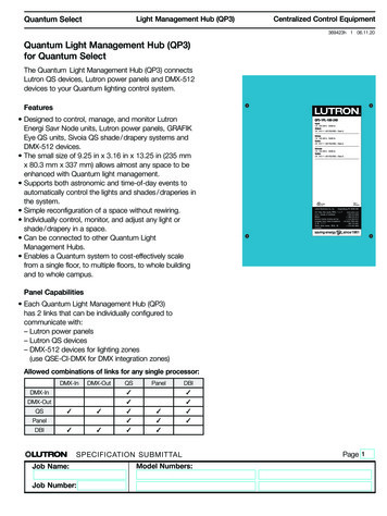
Lock functionality testing1.a.b.Initial Lock Test (Construction Mode)Present a valid opening key to the readerEnsure lock unlatches, lever turns freely, and lock re-latches2.a.Lock ProgrammingUse HH6 to program lock to desired room number (see figure #13 for USB programming port)Figure 13 - USB Programming Cable Connection3.a.b.c.Reader Cover InstallationLocate release hole at 5:00 (see figure #14)Place the lens onto the base and rotate clockwise to secure at 6:00Ensure cover is secured (locking tab will click when fully seated)*For ease of assembly and disassembly; wrap thumb around circumference of cover to get a good gripFigure 14 - Reader Cover Installation10Saflok Quantum PixelPK3693 T09-21
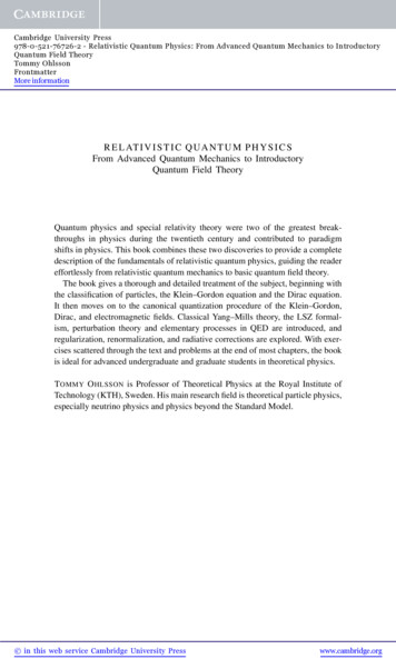
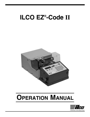
Removing the cover4.a.b.c.d.e.f.g.Final Lock TestPresent a valid opening key to readerEnsure reader flashes the green LED 8 timesEnsure lock unlatches, lever turns freely, and lock re-latchesWith door open; throw deadbolt and activate privacyPresent valid opening key to readerEnsure reader flashes the yellow LED 12 timesRotate inside lever to retract deadbolt and thumb turn*Ensure I/S lever retracts smoothlyRefer to the table below for other LED feedback:Lock CommunicationElectronic Function DescriptionRed and green LEDs flash 9 times simultaneouslyTime and date not set, use the Quantum LPI probeto resetYellow LED flashes 12 timesDead bolt is thrown or switch cam is not properlyalignedYellow LED flashes 2 timesKeycard not allowed OR keycard cancelled by newkeycardRed and green LEDs flash alternately 9 timesLow battery (contact the SAFLOK servicedepartment)Yellow and red LEDs flash 2 times simultaneouslyBad keycard read or corrupted data (may requirenew keycard)5.a.b.Reader Cover RemovalInsert cover removal tool through release hole at bottom to unlock locking tabRotate cover counter-clockwise while maintaining upward pressure on locking tab*A32360 Cover removal tool can be attached to HH6 programming cable or keychainFigure 15 - Cover Removal Tool AlignmentProgrammingCable SlotCover Removal Tool AlignmentSaflok Quantum PixelPK3693 TKeychain HoleA32360 Cover Removal Tool09-2111
Door Unit Inspection CriteriaAppearance Finish is free of blemishes or scratches that would distract from lock appearance Lock body and under plate (if used) are mounted straight on the door Door scalp is mounted straight and flush with the door edge Jamb strike is mounted straight and is flush with the jamb face Correction of minor blemishes on the door jamb are the responsibility of the property’smaintenancedepartmentLock Function Knob or lever rotates and moves freely Lever is horizontal to floor when at rest position Dead bolt extends fully and retracts without binding (door open) Lock latch and dead bolt engage jamb strike plate freely Anti-pick latch when depressed (door open) Anti-pick latch is depressed when contact is made with the strike plate (door closed)Electronics/Keycards Present keycard in front of reader, and the yellow light flashes twice when incorrect keycard is used Green light flashes when the proper keycard is used Green light is flashing when the lever is operated Green light continues to flash for a five-second cycle Yellow light flashes 12 times when the dead bolt is extended and a guest/hotel keycard is used All keycards function to the specifications of the properties key designDoor function Door closes and latches with little or no interference Dead bolt extends fully through the strike plate without interference (door closed) Spacing between door edge and inside door jamb does not exceed 3/16” (door closed)Note: If bumpers or other seals are added after strike plate installation and causes alignment and latchproblems, it is the property’s responsibility to correct this condition. This note generally applies to newconstruction or new door installation.12Saflok Quantum PixelPK3693 T09-21
FCC and IC WarningsFCC Interference Statement (Part 15.105 (b)):This equipment has been tested and found to comply with the limits for a Class B digital device, pursuantto Part 15 of the FCC Rules. These limits are designed to provide reasonable protection against harmfulinterference in a residential installation. This equipment generates uses and can radiate radio frequencyenergy and, if not installed and used in accordance with the instructions, may cause harmful interferenceto radio communications. Howev er, there is no guarantee that interference will not occur in a particularinstallation. If this equipment does cause harmful interference to radio or television reception, whichcan be determined by turning the equipment off and on, the user is encouraged to try to correct theinterference by one of the following measures:Reorient or relocate the receiving antenna.Increase the separation between the equipment and receiver.Connect the equipment into an outlet on a circuit different from that to which the receiver is connected.Consult the dealer or an experienced radio/TV technician for help.This device complies with Industry Canada licence-exempt RSS standard(s). Operation is subject to thefollowing two conditions: (1) this device may not cause interference, and (2) this device must accept anyinterference, including interference that may cause undesired operation of the device.Le présent appareil est conforme aux CNR d'Industrie Canada applicables aux appareils radio exempts delicence. L'exploitation est autorisée auxdeux conditions suivantes : (1) l'appareil ne doit pas produire de brouillage, et (2) l'utilisateur de l'appareildoit accepter tout brouillage radioélectriquesubi, même si le brouillage est susceptible d'en compromettre le fonctionnement.Saflok Quantum PixelPK3693 T09-2113
dormakaba USA Inc.Customer Services & SupportSaflok: 1.800.999.6213 / t to change without noticeGeneral information:dormakaba.usOnline consumable orders:www.saflokstore.comTo access all of our easy steps, pleasevisit our support website:www.dormakabalodgingsupport.com
10 Saflok Quantum Pixel PK3693_T 09-21 Lock functionality testing 1. Initial Lock Test (Construction Mode) a. Present a valid opening key to the reader b. Ensure lock unlatches, lever turns freely, and lock re-latches 2. Lock Programming a. Use HH6 to program lock to desired room number (see figure #13 for USB programming port)