Transcription
WHITE PA P E RThermally Conductive PottingCompounds Enable Higher PowerDensity ElectronicsDaniel Barber, Staff Scientist, and Eric Wyman, Scientist,Electronic Materials Technology, LORD Corporation
Thermally Conductive PottingCompounds Enable Higher PowerDensity ElectronicsABSTRACTA key challenge in developing higher power densityelectronics for electric vehicles and other applicationsis to manage the heat generated by smaller, highpower devices, such as on-board battery chargers,power inverters and converters, and electric machines.Thermally conductive potting compounds are proving tobe an ideal method for rapidly and effectively conductingheat away from power components to the heat sink. Inthis study, we examine the heat rise of inductors pottedin a liquid-cooled aluminum fixture using LORD siliconepotting materials with thermal conductivities ranging from0.1 to 4.0 W/m K. Comparing an inductor potted with aninsulating material (0.1 W/m K) to the most conductivematerial (4.0 W/m K), the heat rise is decreased by about50 C, and the time required to reach a stable temperatureis decreased from nearly two hours to about 15 minutes.These significant improvements in heat managementenable the development of dramatically smaller powerelectronics, saving weight, space, and cost.INTRODUCTIONCurrently, there is a strong trend toward the electrificationof vehicles in the transportation industry, includingautomobiles, buses, trains, off-road vehicles, watercraft,and aircraft. Long ranges and/or high horsepower requirehigh power density from their electrical componentssuch as batteries, motors and generators, and the powerelectronics needed for operation. The trend is towardssmaller, lighter, and less expensive components thatwill save space and reduce costs while boosting powerefficiency.2One key challenge in developing these types ofcomponents is to manage the heat generated by smaller,high-power devices like on-board battery chargers,power inverters and converters, and electric machines.Thermally conductive potting compounds are proving tobe an ideal method for rapidly and effectively conductingheat away from power components to the heat sink. Thepotting compound fills the component enclosure entirely,leaving no air gaps. As a result, heat is dissipated withinthe enclosure and rapidly conducted to the heat sink,which has enabled substantial size and weight reductionsof the finished component.LORD Corporation has been supplying thermallyconductive, electrically insulating potting materials tothe power electronics industry for over a decade, andrecently, we have been testing the effectiveness of usingpotting compounds with high thermal conductivity todissipate heat in high-power applications. For example,we have demonstrated substantial temperature reductionsand improved power output using LORD CoolThermTMSC-320 Thermally Conductive Silicone Encapsulant to potthe end windings of electric motors. (For more informationon this topic please access our white paper, “How ProperApplication of Thermally Conductive Materials WillImprove Motor Power Density,” atwww.lord.com/thermconductpaper). In this white paper,we present the results of another study on the ability ofLORD thermally conductive silicone materials to rapidlyand effectively remove heat from high-power inductors.
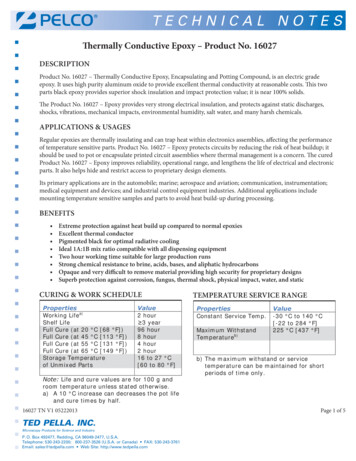
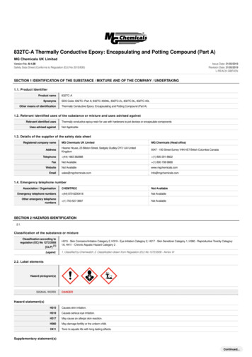
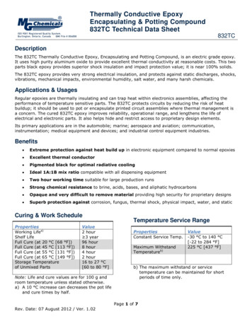
POTTING MATERIALS USED IN THE STUDYINDUCTOR POTTING AND TESTINGFive different LORD silicone potting materials wereused in this study. All of the materials are electricallyinsulating with high dielectric strength and excellenthigh-temperature stability. LORD ThermosetTM SC-400Silicone Encapsulant is a clear, soft gel with low thermalconductivity (0.1 W/m K) used for potting sensitiveelectronics where high dielectric strength and very lowmechanical stress are desired. LORD CoolTherm SC-305,SC-309, SC-320, and SC-324 Thermally ConductiveSilicone Encapsulant are filled silicone potting materialswith progressively higher thermal conductivities of 0.7,1.0, 3.0, and 4.0 W/m K, respectively. These materialsare currently being used in numerous applications toprotect sensitive electronic components from excess heat,including LED driver electronics, on-board chargers andinverters for electric vehicles, and electric motor stators.The inductors used in this study were made fromMicrometals T400-61D high-temperature, magneticpowder toroid cores wrapped with 62 turns of 10-gaugeinsulated copper wire, which yield about 500 μHinductance at load. Inductors were potted in custommade aluminum cooling plates fitted with liquid inlet andoutlet ports for connection to an external circulating fluidbath. The five different materials were used to pot threeinductors with each material, resulting in a total of 15potted inductors. One set of potted inductors is shownin Figure 2. Before potting, each inductor was fitted witha thermocouple to measure its temperature during thetest. (See Figure 3.) The location of the thermocouplecorresponds to the hottest location in the inductor asjudged qualitatively from a thermal camera image of anunpotted inductor under load.A key differentiating property of LORD thermallyconductive silicone materials is their low viscositycompared to competitor materials with similar thermalconductivity. The lower viscosity allows LORD materials toflow and fill voids more readily while providing excellentthermal conductivity. They are also easier to degas,meaning that parts can be potted that are essentially voidfree if a vacuum potting process is used. Figure 1 showsthermal conductivity versus viscosity of LORD siliconematerials as compared to various competitor products.Technical data sheets for all commercial products can befound at www.lord.com.Figure 2: Inductors potted in aluminum cooling plates with each of theLORD potting materials.Thermocouple forinductor temperatureFigure 3: Detail showing the thermocouple location on the inductor, onthe inner edge of the toroid opposite the wire leads.Figure 1: Thermal conductivity versus viscosity for various potting materials.Commercially-available LORD materials are indicated as red circles.3
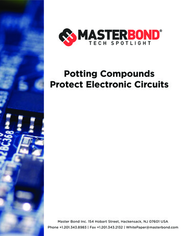
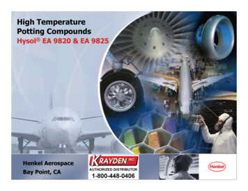
For the thermal tests, each inductor was connected to aManzanita Micro PFC40X-188 charger passing 9.3 kWand 40 A at 240V input with 0.98 power factor. Power atthe inductor was 30W. The aluminum cooling plate wasconnected to a temperature-controlled liquid bath; eachinductor was tested at coolant temperature set points of25 C, and the typical automotive coolant temperature of50 C. A second thermocouple was attached to the exteriorof the cooling plate to monitor temperature changesduring the test; however, the temperature rise of thecooling plate was less than 2 C even in the most extremecases and, accordingly, will not be considered further. Thecomplete set-up is shown in Figure 4.During each thermal test, the temperatures of the inductorand cooling plate were recorded using an Omega Softdata logger. The cooling plate and inductor temperatureswere allowed to stabilize with no power. Power was thenapplied, and the temperature was monitored until theinductor temperature stabilized. The equilibration time waschosen at the point when the temperature reached steadystate (no further temperature increase took place), andthe reported temperature rise was calculated as the finaltemperature of the inductor minus the initial temperature.Figure 5 shows a representative plot for an inductor pottedwith Thermoset SC-400 encapsulant with the parametersindicated.Figure 4: Test set-up for one inductor potted with Thermost SC-400encapsulant showing the PFC40X-188 charger on the left, the pottedinductor on the right, and the coolant inlet and outlet lines at the far right.Figure 5: Temperature profile for a typical Thermoset SC-400 encapsulant potted inductor test, showing definitions of temperature rise andequilibration time. The blue line is the inductor, and the nearly-horizontal red line is the cooling plate.4
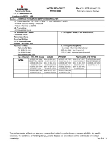
RESULTS OF THE STUDYEach of the 15 inductors were tested at least one time,and several of the inductors were tested multiple times todetermine repeatability. The average temperature rise andequilibration time data are summarized in Figures 6 and7. Error bars are plus and minus one standard deviationof the data, which includes part-to-part variation andrepeatability.The data show that both the inductor temperaturerise and the equilibration time are independent of thecoolant temperature, as the data at 25 C and 50 C arenearly superimposable and within the test variation. It isimportant to note that the variation becomes much smalleras the thermal conductivity increases due to the moreeffective thermal connection to the aluminum coolingplate.Dramatic reductions in both temperature rise andequilibration time are observed for inductors pottedwith thermally conductive materials. (See Figure 6.)The average temperature rise with Thermoset SC-400encapsulant was about 55 C, and the average rise for themost thermally conductive materials, CoolTherm SC-320and SC-324 encapsulants, was less than 10 C. Even themoderately conductive silicones, CoolTherm SC-305 andSC-309 encapsulants at 0.7 and 1.0 W/m K, respectively,provided significant improvements. Under different testconditions that would generate a temperature rise muchgreater than 55 C, it is likely that the improvement wouldbe even more pronounced.Figure 6: Average temperature rise for inductors in the study at both 25 C and 50 C set points of the liquid coolant.5
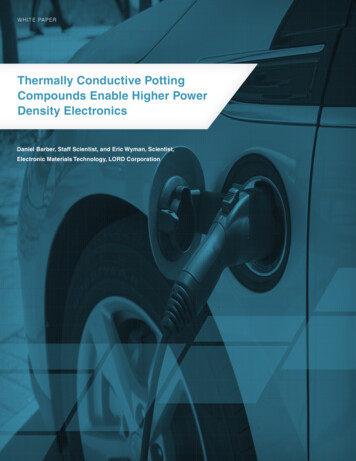
Similarly, the equilibration time was also dramaticallyreduced with the higher thermally conductive materials.(See Figure 7.) With the non-conductive silicone,Thermoset SC-400 encapsulant, nearly two hourswas required to reach steady state, whereas a stabletemperature was achieved in less than 20 minutes forCoolTherm SC-320 and SC-324 encapsulants. This rapidtemperature recovery means that heat is dissipatedquickly and components will spend less time at elevatedtemperatures, thus increasing the lifetime of thecomponents.CONCLUSIONSProper thermal management is essential for developingpower electronics that are smaller and lighter, andsmaller and lighter means higher power density. UsingLORD thermal management materials that provide theunique combination of high thermal conductivity and lowviscosity, we have demonstrated substantial reductionsin both maximum temperature rise and the time to reacha stable temperature. Both of these benefits bring aboutimprovements in efficiency and component lifetime,thereby enabling high-performance power electronics.Figure 7: Average time to reach steady-state temperature (equilibration time) for inductors in the study at both 25 C and 50 C set points of theliquid coolant.Acknowledgement:LORD Corporation would like to thank Rich Rudman and his staff at Manzanita Micro for providing lab space, testequipment, and electronics expertise for this study.6
7
CoolTherm, Thermoset and “Ask Us How” are trademarks of LORD Corporation or one of its subsidiaries.LORD provides valuable expertise in adhesives and coatings, vibration and motion control, and magnetically responsivetechnologies. Our people work in collaboration with our customers to help them increase the value of their products. Innovative andresponsive in an ever-changing marketplace, we are focused on providing solutions for our customers worldwide . Ask Us How.LORD CorporationWorld Headquarters111 Lord DriveCary, NC 27511-7923USACustomer Support Center (in United States & Canada) 1 877 ASK LORD (275 5673)www.lord.comFor a listing of our worldwide locations, visit LORD.com. 2017 LORD Corporation OD LL3244 (Rev.1 8/17)
Thermally conductive potting compounds are proving to be an ideal method for rapidly and effectively conducting heat away from power components to the heat sink. The potting compound fills the component enclosure entirely, leaving no air gaps. As a result, heat is dissipated within the enclosure and rapidly conducted to the heat sink,