Transcription
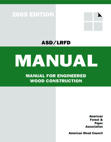
2005 EDITIONASD/LRFDMANUALMANUAL FOR ENGINEEREDWOOD CONSTRUCTIONAmericanForest &PaperAssociationAmerican Wood Council
Updates and ErrataWhile every precaution has been taken toensure the accuracy of this document, errorsmay have occurred during development.Updates or Errata are posted to the AmericanWood Council website at www.awc.org.Technical inquiries may be addressed toawcinfo@afandpa.org.The American Wood Council (AWC) is the wood products division of the American Forest & PaperAssociation (AF&PA). AF&PA is the national trade association of the forest, paper, and wood productsindustry, representing member companies engaged in growing, harvesting, and processing wood andZRRG ¿EHU PDQXIDFWXULQJ SXOS SDSHU DQG SDSHUERDUG SURGXFWV IURP ERWK YLUJLQ DQG UHF\FOHG ¿EHU and producing engineered and traditional wood products. For more information see www.afandpa.org.
2005 EDITIONASD/LRFDMANUALFOR ENGINEEREDWOOD CONSTRUCTIONCopyright 2006American Forest & Paper Association, Inc.
iiASD/LRFD MANUAL FOR ENGINEERED WOOD CONSTRUCTIONASD/LRFD Manual for Engineered Wood Construction 2005 EditionWeb Version: September 2008ISBN 0-9625985-7-7 (Volume 3)ISBN 0-9625985-8-5 (4 Volume Set)Copyright 2006 by American Forest & Paper Association, Inc.All rights reserved. No part of this publication may be reproduced, distributed, or transmitted in any form or by anymeans, including, without limitation, electronic, optical, or mechanical means (by way of example and not limitation,photocopying, or recording by or in an information storage retrieval system) without express written permission of theAmerican Forest & Paper Association, Inc. For information on permission to copy material, please contact:Copyright PermissionAF&PA American Wood Council1111 Nineteenth St., NW, Suite 800Washington, DC 20036email: awcinfo@afandpa.orgPrinted in the United States of AmericaAMERICAN WOOD COUNCIL
ASD/LRFD MANUAL FOR ENGINEERED WOOD CONSTRUCTIONiiiFOREWORDThis Allowable Stress Design/Load and ResistanceFactor Design Manual for Engineered Wood Construction(ASD/LRFD Manual) provides guidance for design of mostwood-based structural products used in the constructionof wood buildings. The complete Wood Design Packageincludes this ASD/LRFD Manual and the following: ANSI/AF&PA NDS-2005 National Design Speci¿FDWLRQ (NDS ) for Wood Construction – withCommentary; and, NDS Supplement – Design Values for Wood Construction, 2005 Edition, ANSI/AF&PA SDPWS-05 – Special Design Provisions for Wind and Seismic (SDPWS) – withCommentary, ASD/LRFD Structural Wood Design Solved Example Problems, 2005 Edition.SURGXFWV IRU RYHU \HDUV ¿UVW LQ WKH IRUP RI WKH WoodStructural Design Data series and then in the National'HVLJQ 6SHFL¿FDWLRQ 1'6 IRU :RRG &RQVWUXFWLRQ.It is intended that this document be used in conjunctionwith competent engineering design, accurate fabrication,and adequate supervision of construction. AF&PA does notassume any responsibility for errors or omissions in thedocument, nor for engineering designs, plans, or construction prepared from it.Those using this standard assume all liability arisingfrom its use. The design of engineered structures is withinthe scope of expertise of licensed engineers, architects, orother licensed professionals for applications to a particularstructure.The American Forest & Paper Association (AF&PA)has developed this manual for design professionals.AF&PA and its predecessor organizations have providedengineering design information to users of structural woodAMERICAN FOREST & PAPER ASSOCIATIONAmerican Forest & Paper Association
ivASD/LRFD MANUAL FOR ENGINEERED WOOD CONSTRUCTIONAMERICAN WOOD COUNCIL
ASD/LRFD MANUAL FOR ENGINEERED WOOD CONSTRUCTIONvTABLE OF CONTENTSPart/TitleM1PageGENERAL REQUIREMENTSFOR STRUCTURAL DESIGN .1Part/TitleM7M1.1 Products Covered in This ManualM1.2 General RequirementsM1.3 Design ProceduresM2DESIGN VALUES FORSTRUCTURAL MEMBERS . 3M2.1 General InformationM2.2 Reference Design ValuesM2.3 Adjustment of Design ValuesM3M4SAWN LUMBER . 11M4.1 GeneralM4.2 Reference Design ValuesM4.3 Adjustment of Reference DesignValuesM4.4 Special Design ConsiderationsM4.5 Member Selection TablesM4.6 Examples of Capacity TableDevelopmentM5STRUCTURAL GLUEDLAMINATED TIMBER . 27M5.1 GeneralM5.2 Reference Design ValuesM5.3 Adjustment of Reference DesignValuesM5.4 Special Design ConsiderationsM6ROUND TIMBER POLESAND PILES. 33M6.1 GeneralM6.2 Reference Design ValuesM6.3 Adjustment of Reference DesignValuesM6.4 Special Design ConsiderationsPREFABRICATED WOODI-JOISTS . 37M7.1 GeneralM7.2 Reference Design ValuesM7.3 Adjustment of Reference DesignValuesM7.4 Special Design ConsiderationsM8STRUCTURAL COMPOSITELUMBER . 53M8.1 GeneralM8.2 Reference Design ValuesM8.3 Adjustment of Reference DesignValuesM8.4 Special Design ConsiderationsDESIGN PROVISIONS ANDEQUATIONS . 5M3.1 GeneralM3.2 Bending Members - GeneralM3.3 Bending Members - FlexureM3.4 Bending Members - Shear0 %HQGLQJ 0HPEHUV 'HÀHFWLRnM3.6 Compression MembersM3.7 Solid ColumnsM3.8 Tension MembersM3.9 Combined Bending and Axial LoadingM3.10 Design for BearingPageM9WOOD STRUCTURALPANELS .59M9.1 GeneralM9.2 Reference Design ValuesM9.3 Adjustment of Reference DesignValuesM9.4 Special Design ConsiderationsM10 MECHANICALCONNECTIONS .69M10.1M10.2M10.3M10.4M10.5GeneralReference Design ValuesDesign Adjustment FactorsTypical Connection DetailsPre-Engineered Metal ConnectorsM11 DOWEL-TYPE FASTENERS. 85M11.1 GeneralM11.2 Reference Withdrawal DesignValuesM11.3 Reference Lateral Design ValuesM11.4 Combined Lateral and WithdrawalLoadsM11.5 Adjustment of Reference DesignValuesM11.6 Multiple FastenersM12 SPLIT RING AND SHEARPLATE CONNECTORS. 89M12.1 GeneralM12.2 Reference Design ValuesM12.3 Placement of Split Ring and ShearPlate ConnectorsAMERICAN FOREST & PAPER ASSOCIATION
viASD/LRFD MANUAL FOR ENGINEERED WOOD CONSTRUCTIONPart/TitlePageM13 TIMBER RIVETS. 91Part/TitleM16 FIRE DESIGN . 101M13.1 GeneralM13.2 Reference Design ValuesM13.3 Placement of Timber RivetsM14 SHEAR WALLS ANDDIAPHRAGMS . 93M14.1M14.2M14.3M14.4PageGeneralDesign PrinciplesShear WallsDiaphragmsM15 SPECIAL LOADINGCONDITIONS.99M15.1 Lateral Distribution ofConcentrated LoadsM15.2 Spaced ColumnsM15.3 Built-Up ColumnsM15.4 Wood Columns with Side Loadsand EccentricityAMERICAN WOOD COUNCILM16.1 GeneralM16.2 Design Procedures for ExposedWood MembersM16.3 Wood Connections
ASD/LRFD MANUAL FOR ENGINEERED WOOD CONSTRUCTIONviiLIST OF TABLESM4.3-1Applicability of Adjustment Factors forSawn Lumber . 13M4.4-1Approximate Moisture and ThermalDimensional Changes. 140 &RHI¿FLHQW RI 0RLVWXUH ([SDQVLRQ HME,and Fiber Saturation Point, FSP, for SolidWoods . 150 &RHI¿FLHQW RI 7KHUPDO ([SDQVLRQ HTE, forSolid Woods . 16M4.5-1aASD Tension Member Capacity (T'),Structural Lumber (2-inch nominal thicknessVisually Graded Lumber (1.5 inch drydressed size), CD 1.0.4-inch nominalthickness Visually Graded Lumber (3.5inch dry dressed size), CD 1.0) . 18M4.5-1b ASD Tension Member Capacity (T'),Structural Lumber (2-inch nominalthickness MSR Lumber (1.5 inch drydressed size), CD 1.0) . 18M4.5-2aASD Column Capacity (P', P'x, P'y), Timbers(6-inch nominal thickness (5.5 inch drydressed size), CD 1.0) . 19M4.5-2b ASD Column Capacity (P', P'x, P'y), Timbers(8-inch nominal thickness (7.5 inch drydressed size), CD 1.0) . 20M4.5-2cM4.5-3aASD Column Capacity (P', P'x, P'y), Timbers(10-inch nominal thickness (9.5 inch drydressed size), CD 1.0) . 21ASD Bending Member Capacity (M',CrM', V', and EI), Structural Lumber (2-inchnominal thickness (1.5 inch dry dressedsize), CD 1.0, CL 1.0) . 22M4.5-3b ASD Bending Member Capacity (M', CrM',V', and EI), Structural Lumber (4-inchnominal thickness (3.5 inch dry dressedsize), CD 1.0, CL 1.0. . 22M4.5-4aASD Bending Member Capacity (M', V',and EI), Timbers (6-inch nominal thickness(5.5 inch dry dressed size), CD 1.0,CL 1.0) . 23M4.5-4b ASD Bending Member Capacity (M', V',and EI), Timbers (8-inch nominalthickness (7.5 inch dry dressed size),CD 1.0, CL 1.0). 23M4.5-4cASD Bending Member Capacity (M', V',and EI), Timbers (10-inch nominalthickness (9.5 inch dry dressed size),CD 1.0, CL 1.0). 24M4.5-4d ASD Bending Member Capacity (M', V',and EI), Timbers (Nominal dimensions 10 inch (actual nominal – 1/2 inch),CD 1.0, CL 1.0). 24M5.1-1Economical Spans for Structural GluedLaminated Timber Framing Systems . 29M5.3-1Applicability of Adjustment Factors forStructural Glued Laminated Timber. 310 YHUDJH 6SHFL¿F *UDYLW\ DQG :HLJKW Factor . 32M6.3-1Applicability of Adjustment Factors forRound Timber Poles and Piles . 35M7.3-1Applicability of Adjustment Factors forPrefabricated Wood I-Joists . 40M8.3-1Applicability of Adjustment Factors forStructural Composite Lumber . 56M9.1-1Guide to Panel Use . 61M9.2-1Wood Structural Panel Bending Stiffnessand Strength . 62M9.2-2Wood Structural Panel Axial Stiffness,Tension, and Compression Capacities. 63M9.2-3Wood Structural Panel Planar (Rolling)Shear Capacities . 65M9.2-4Wood Structural Panel Rigidity andThrough-the-Thickness Shear Capacities . 65M9.3-1Applicability of Adjustment Factors forWood Structural Panels . 66M9.4-1Panel Edge Support . 67M9.4-2Minimum Nailing for Wood StructuralPanel Applications. 68M10.3-1 Applicability of Adjustment Factors forMechanical Connections . 71AMERICAN FOREST & PAPER ASSOCIATION
viiiM11.3-1ASD/LRFD MANUAL FOR ENGINEERED WOOD CONSTRUCTIONApplicability of Adjustment Factors forDowel-Type Fasteners . 87M12.2-1 Applicability of Adjustment Factors forSplit Ring and Shear Plate Connectors . 90M13.2-1 Applicability of Adjustment Factors forTimber Rivets . 92M16.1-1 Minimum Sizes to Qualify as HeavyTimber Construction . 102M16.1-2 One-Hour Fire-Rated Load-BearingWood-Frame Wall Assemblies .103M16.1-3 Two-Hour Fire-Rated Load-BearingWood-Frame Wall Assemblies . 103M16.1-4 One-Hour Fire-Rated Wood Floor/CeilingAssemblies . 104M16.1-5 Two-Hour Fire-Rated Wood Floor/CeilingAssemblies . 104M16.1-6 Minimum Depths at Which Selected BeamSizes Can Be Adopted for One-Hour FireRatings . 119M16.1-7 Fire-Resistive Wood I-Joist Floor/CeilingAssemblies . 123M16.1-8 Privacy Afforded According to STCRating . 143M16.1-9 Contributions of Various Products to STCor IIC Rating . 143M16.1-10 Example Calculation . 144M16.1-11 STC & IIC Ratings for UL L528/L529 . 144M16.1-12 STC & IIC Ratings for FC-214 . 144M16.2-1 Design Load Ratios for BendingMembers Exposed on Three Sides(Structural Calculations at StandardReference Conditions: CD 1.0, CM 1.0,Ct 1.0, Ci 1.0, CL 1.0) (ProtectedSurface in Depth Direction) . 147M16.2-2 Design Load Ratios for Bending MembersExposed on Four Sides (StructuralCalculations at Standard ReferenceConditions: CD 1.0, CM 1.0, Ct 1.0,Ci 1.0, CL 1.0) .148M16.2-3 Design Load Ratios for CompressionMembers Exposed on Three Sides(Structural Calculations at StandardReference Conditions: CM 1.0, Ct 1.0,Ci 1.0) (Protected Surface in DepthDirection) . 149M16.2-4 Design Load Ratios for CompressionMembers Exposed on Three Sides(Structural Calculations at StandardReference Conditions: CM 1.0, Ct 1.0,Ci 1.0) (Protected Surface in WidthDirection) . 150M16.2-5 Design Load Ratios for CompressionMembers Exposed on Four Sides(Structural Calculations at StandardReference Conditions: CM 1.0, Ct 1.0,Ci 1.0) . 151M16.2-6 Design Load Ratios for Tension MembersExposed on Three Sides (StructuralCalculations at Standard ReferenceConditions: CD 1.0, CM 1.0, Ct 1.0,Ci 1.0) (Protected Surface in DepthDirection) . 152M16.2-7 Design Load Ratios for Tension MembersExposed on Three Sides (StructuralCalculations at Standard ReferenceConditions: CD 1.0, CM 1.0, Ct 1.0,Ci 1.0) (Protected Surface in WidthDirection) . 153M16.2-8 Design Load Ratios for Tension MembersExposed on Four Sides (StructuralCalculations at Standard ReferenceConditions: CD 1.0, CM 1.0, Ct 1.0,Ci 1.0) . 154M16.2-9 Design Load Ratios for Exposed TimberDecks (Double and Single Tongue &Groove Decking) (Structural Calculationsat Standard Reference Conditions:CD 1.0, CM 1.0, Ct 1.0, Ci 1.0). 155M16.2-10 Design Load Ratios for Exposed TimberDecks (Butt-Joint Timber Decking)(Structural Calculations at StandardReference Conditions: CD 1.0, CM 1.0,Ct 1.0, Ci 1.0) . 155AMERICAN WOOD COUNCIL
ASD/LRFD MANUAL FOR ENGINEERED WOOD CONSTRUCTIONixLIST OF FIGURESM5.1-1Unbalanced and Balanced LayupCombinations . 28M5.2-1Loading in the X-X and Y-Y Axes . 30M7.4-1Design Span Determination . 41M7.4-2Load Case Evaluations . 43M7.4-3End Bearing Web Stiffeners (BearingBlock) . 45M7.4-4Web Stiffener Bearing Interface . 46M7.4-5Beveled End Cut . 46M7.4-6Sloped Bearing Conditions (Low End) . 47M7.4-7Sloped Bearing Conditions (High End) . 48M7.4-8Lateral Support Requirements for Joistsin Hangers . 49M7.4-9Top Flange Hanger Support . 49M7.4-10 Connection Requirements for Face NailHangers . 50M7.4-11Details for Vertical Load Transfer . 51M9.2-1Structural Panel with Strength DirectionAcross Supports . 60M9.2-2Example of Structural Panel in Bending . 60M9.2-3Structural Panel with Axial CompressionLoad in the Plane of the Panel. 64M9.2-4Through-the-Thickness Shear for WoodStructural Panels. 64M9.2-5Planar (Rolling) Shear or Shear-in-thePlane for Wood Structural Panels. 64M14.2-1 Shear Wall Drag Strut . 94M14.2-2 Shear Wall Special Case Drag Strut . 95M14.2-3 Diaphragm Drag Strut (Drag strut parallelto loads) . 95M14.2-4 Diaphragm Chord Forces . 96M14.3-1 Overturning Forces (no dead load) . 97M16.1-1 One-Hour Fire-Resistive Wood WallAssembly (WS4-1.1) (2x4 Wood StudWall - 100% Design Load - ASTME119/NFPA 251) . 105M16.1-2 One-Hour Fire-Resistive Wood WallAssembly (WS6-1.1) (2x6 Wood StudWall - 100% Design Load - ASTME119/NFPA 251) . 106M16.1-3 One-Hour Fire-Resistive Wood WallAssembly (WS6-1.2) (2x6 Wood StudWall - 100% Design Load - ASTME119/NFPA 251) . 107M16.1-4 One-Hour Fire-Resistive Wood WallAssembly (WS6-1.4) (2x6 Wood StudWall - 100% Design Load - ASTME119/NFPA 251) . 108M16.1-5 One-Hour Fire-Resistive Wood WallAssembly (WS4-1.2) (2x4 Wood StudWall - 100% Design Load - ASTME119/NFPA 251 . 109M16.1-6 One-Hour Fire-Resistive Wood WallAssembly (WS4-1.3) (2x4 Wood StudWall - 78% Design Load - ASTME119/NFPA 251) . 110M16.1-7 One-Hour Fire-Resistive Wood WallAssembly (WS6-1.3) (2x6 Wood StudWall - 100% Design Load - ASTME119/NFPA 251) .111M16.1-8 One-Hour Fire-Resistive Wood WallAssembly (WS6-1.5) (2x6 Wood StudWall - 100% Design Load - ASTME119/NFPA 25) . 112M16.1-9 Two-Hour Fire-Resistive Wood WallAssembly (WS6-2.1) (2x6 Wood StudWall - 100% Design Load - ASTME119/NFPA 251) . 113M16.1-10 One-Hour Fire-Resistive WoodFloor/Ceiling Assembly (2x10 Wood Joists16" o.c. – Gypsum Directly Applied or onOptional Resilient Channels) . 114M14.3-2 Overturning Forces (with dead load) . 97AMERICAN FOREST & PAPER ASSOCIATION
xASD/LRFD MANUAL FOR ENGINEERED WOOD CONSTRUCTIONM16.1-11 One-Hour Fire-Resistive WoodFloor/Ceiling Assembly (2x10 Wood Joists16" o.c. – Suspended Acoustical CeilingPanels) . 115M16.1-18 One-Hour Fire-Resistive CeilingAssembly (WIJ-1.4) (Floor/Ceiling 100% Design Load - 1-Hour Rating ASTM E119/NFPA 251) . 127M16.1-12 One-Hour Fire-Resistive Wood Floor/CeilingAssembly (2x10 Wood Joists 16" o.c.– Gypsum on Resilient Channels) . 116M16.1-19 One-Hour Fire-Resistive CeilingAssembly (WIJ-1.5) (Floor/Ceiling 100% Design Load - 1-Hour Rating ASTM E119/NFPA 251) . 128M16.1-13 One-Hour Fire-Resistive WoodFloor/Ceiling Assembly (2x10 WoodJoists 24" o.c. – Gypsum on ResilientChannels) . 117M16.1-14 Two-Hour Fire-Resistive WoodFloor/Ceiling Assembly (2x10 WoodJoists 16" o.c. – Gypsum Directly Appliedwith Second Layer on ResilientChannels) . 118M16.1-15 One-Hour Fire-Resistive Ceiling Assembly(WIJ-1.1) (Floor/Ceiling - 100% DesignLoad - 1-Hour Rating - ASTME119/NFPA 251) . 124M16.1-16 One-Hour Fire-Resistive CeilingAssembly (WIJ-1.2) (Floor/Ceiling 100% Design Load - 1 Hour Rating ASTM E119/NFPA 251) . 125M16.1-17 One-Hour Fire-Resistive CeilingAssembly (WIJ-1.3) (Floor/Ceiling 100% Design Load - 1-Hour Rating ASTM E119/NFPA 251) . 126M16.1-20 One-Hour Fire-Resistive CeilingAssembly (WIJ-1.6) (Floor/Ceiling 100% Design Load - 1-Hour Rating ASTM E119/NFPA 251) . 129M16.1-21 Two-Hour Fire-Resistive CeilingAssembly (WIJ-2.1) (Floor/Ceiling 100% Design Load - 2-Hour Rating ASTM E119/NFPA 251) . 130M16.1-22 Cross Sections of Possible One-HourArea Separations . 139M16.1-23 Examples of Through-PenetrationFirestop Systems . 142M16.3-1 Beam to Column Connection Connection Not Exposed to Fire . 159M16.3-2 Beam to Column Connection - ConnectionExposed to Fire Where Appearance is aFactor . 159M16.3-3 Ceiling Construction . 159M16.3-4 Beam to Column Connection - ConnectionExposed to Fire Where Appearance isNot a Factor . 159M16.3-5 Column Connections Covered . 160M16.3-6 Beam to Girder - ConcealedConnection . 160AMERICAN WOOD COUNCIL
ASD/LRFD MANUAL FOR ENGINEERED WOOD CONSTRUCTION11M1: GENERALREQUIREMENTSFORSTRUCTURALDESIGNM1.1Products Covered in This Manual2M1.2General Requirements2M1.2.1 Bracing2Design Procedures2M1.3AMERICAN FOREST & PAPER ASSOCIATION
2M1: GENERAL REQUIREMENTS FOR STRUCTURAL DESIGNM1.1 Products Covered in This ManualThis Manual was developed with the intention of covering all structural applications of wood-based productsand their connections that meet the requirements of thereferenced standards. The Manual is a dual format document incorporating design provisions for both allowablestress design (ASD) and load and resistance factor design(LRFD). Design information is available for the followinglist of products. Each product chapter contains informationfor use with this Manual and the National Design Speci¿FDWLRQ 1'6 IRU :RRG &RQVWUXFWLRQ. Chapters areorganized to parallel the chapter format of the NDS. Sawn LumberStructural Glued Laminated TimberRound Timber Poles and PilesPrefabricated Wood I-JoistsChapter 4Chapter 5Chapter 6Chapter 7 Structural Composite LumberWood Structural PanelsMechanical ConnectionsDowel-Type FastenersSplit Ring and Shear Plate ConnectorsTimber RivetsShear Walls and DiaphragmsChapter 8Chapter 9Chapter 10Chapter 11Chapter 12Chapter 13Chapter 14An additional Supplement, entitled Special DesignProvisions for Wind and Seismic (SDPWS), has beendeveloped to cover materials, design, and construction ofwood members, fasteners, and assemblies to resist windand seismic forces.M1.2 General RequirementsThis Manual is organized as a multi-part package forPD[LPXP ÀH[LELOLW\ IRU WKH GHVLJQ HQJLQHHU ,QFOXGHG LQ this package are: NDS and Commentary; and, NDS Supplement:Design Values for Wood Construction, Special Design Provisions for Wind and Seismic(SDPWS) and Commentary, Structural Wood Design Solved Example Problems.M1.2.1 BracingDesign considerations related to both temporary andSHUPDQHQW EUDFLQJ GLIIHU DPRQJ SURGXFW W\SHV 6SHFL¿F discussion of bracing is included in the product chapter.M1.3 Design ProceduresThe NDS LV D GXDO IRUPDW VSHFL¿FDWLRQ LQFRUSRUDWLQJ design provisions for ASD and LRFD. Behavioral equations, such as those for member and connection design, arethe same for both ASD and LRFD. Adjustment factor tablesinclude applicable factors for determining an adjusted ASDdesign value or an adjusted LRFD design value. NDSAppendix N – (Mandatory) Load and Resistance FactorDesign (LRFD) outlines requirements that are unique toLRFD and adjustment factors for LRFD.The basic design equations for ASD or LRFD requireWKDW WKH VSHFL¿HG SURGXFW UHIHUHQFH GHVLJQ YDOXH PHHW RU exceed the actual (applied) stress or other effect imposedE\ WKH VSHFL¿HG ORDGV ,Q 6' WKH UHIHUHQFH GHVLJQ YDOXHV are set very low, and the nominal load magnitudes are setat once-in-a-lifetime service load levels. This combination produces designs that maintain high safety levels yetremain economically feasible.From a user’s standpoint, the design process is similar using LRFD. The most obvious difference betweenLRFD and ASD is that both the adjusted design valuesand load effect values in ASD will be numerically muchlower than in LRFD. The adjusted design values are lowerEHFDXVH WKH\ DUH UHGXFHG E\ VLJQL¿FDQW LQWHUQDO VDIHW\ adjustments. The load effects are lower because they arenominal (service) load magnitudes. The load combinationequations for use with ASD and LRFD are given in themodel building codes.AMERICAN WOOD COUNCIL
ASD/LRFD MANUAL FOR ENGINEERED WOOD CONSTRUCTIONM2: DESIGNVALUES FORSTRUCTURALMEMBERS2M2.1General Information4M2.2Reference Design Values4M2.3Adjustment of Design Values4AMERICAN FOREST & PAPER ASSOCIATION3
4M2: DESIGN VALUES FOR STRUCTURAL MEMBERSM2.1 General InformationStructural wood products are provided to serve a widerange of end uses. Some products are marketed throughFRPPRGLW\ FKDQQHOV ZKHUH WKH SURGXFWV PHHW VSHFL¿F standards and the selection of the appropriate product isthe responsibility of the user.Other products are custom manufactured to meet theVSHFL¿F QHHGV RI D JLYHQ SURMHFW 3URGXFWV LQ WKLV FDWHJRU\ are metal plate connected wood trusses and custom structural glued laminated timbers. Design of the individualPHPEHUV LV EDVHG RQ FULWHULD VSHFL¿HG E\ WKH DUFKLWHFW RU engineer of record on the project. Manufacture of theseproducts is performed in accordance with the product’smanufacturing standards. Engineering of these productsnormally only extends to the design of the productsthemselves. Construction-related issues, such as load pathanalysis and erection bracing, remain the responsibility ofthe professional of record for the project.M2.2 Reference Design ValuesReference design value designates the allowablestress design value based on normal load duration. Toavoid confusion, the descriptor “reference” is used andserves as a reminder that design value adjustment factorsare applicable for design values in accordance with referHQFHG FRQGLWLRQV VSHFL¿HG LQ WKH NDS – such as normalload duration.Reference design values for sawn lumber and structural glued laminated timber are contained in the NDSSupplement: Design Values for Wood Construction. Reference design values for round timber poles and piles,dowel-type fasteners, split ring and shear plate connectors,and timber rivets are contained in the NDS. Reference design values for all other products are typically containedin the manufacturer’s code evaluation report.M2.3 Adjustment of Design ValuesAdjusted design value designates reference designvalues which have been multiplied by adjustment factors.Basic requirements for design use terminology applicableto both ASD and LRFD. In equation format, this takes thestandard form fb )bƍ ZKLFK LV DSSOLFDEOH WR HLWKHU 6' RU LRFD. Reference design values (Fb, Ft, Fv, Fc, Fc], E, Emin)are multiplied by adjustment factors to determine adjusteddesign values (Fbƍ )tƍ )vƍ )cƍ )c]ƍ (ƍ (minƍ 5HIHUHQFH FRQGLWLRQV KDYH EHHQ GH¿QHG VXFK WKDW D majority of wood products used in interior or in protectedenvironments will require no adjustment for moisture,temperature, or treatment effects.Moisture content (MC) reference conditions are 19%or less for sawn lumber products. The equivalent limit forglued products (structural glued laminated timber, structural composite lumber, prefabricated wood I-joists, andZRRG VWUXFWXUDO SDQHOV LV GH¿QHG DV 0& RU OHVV Temperature reference conditions include sustainedtemperatures up to 100ºF. Note that it has been traditionally assumed that these reference conditions also includecommon building applications in desert locations wheredaytime temperatures will often exceed 100ºF. Examplesof applications that may exceed the reference temperaturerange include food processing or other industrial buildings.Tabulated design values and capacities are for untreated members. Tabulated design values and capacitiesalso apply to wood products pressure treated by an apSURYHG SURFHVV DQG SUHVHUYDWLYH H[FHSW DV VSHFL¿HG IRU load duration factors.An unincised reference condition is assumed. Formembers that are incised to increase penetration of preservative chemicals, use the incising adjustment factorsgiven in the product chapter.7KH HIIHFWV RI ¿UH UHWDUGDQW FKHPLFDO WUHDWPHQW RQ strength shall be accounted for in the design. Referencedesign values, including connection design values, forlumber and structural glued laminated timber pressureWUHDWHG ZLWK ¿UH UHWDUGDQW FKHPLFDOV VKDOO EH REWDLQHG from the company providing the treatment and redryingservice. The impact load duration factor shall not applyWR VWUXFWXUDO PHPEHUV SUHVVXUH WUHDWHG ZLWK ¿UH UHWDUGDQW chemicals.AMERICAN WOOD COUNCIL
ASD/LRFD MANUAL FOR ENGINEERED WOOD CONSTRUCTIONM3: DESIGNPROVISIONSAND EQUATIONS3M3.1General6M3.2Bending Members - General6M3.3Bending Members - Flexure6M3.4Bending Members - Shear60 %HQGLQJ 0HPEHUV 'HÀHFWLRQ 7M3.6Compression Members7M3.7Solid Columns8M3.8Tension Members8M3.8.1 Tension Parallel to Grain8M3.8.2 Tension Perpendicular to Grain 8M3.9Combined Bending and Axial Loading 9M3.10 Design for BearingAMERICAN FOREST & PAPER ASSOCIATION510
6M3: DESIGN PROVISIONS AND EQUATIONSM3.1 GeneralThis Chapter covers design of members for bending,compression, tension, combined bending and axial loads,and bearing.M3.2 Bending Members - GeneralThis section covers design of members stressed priPDULO\ LQ ÀH[XUH EHQGLQJ ([DPSOHV RI VXFK PHPEHUV include primary framing members (beams) and secondaryframing members (purlins, joists). Products commonlyused in these applications include glulam, solid sawnlumber, structural composite lumber, and prefabricatedI-joists.Bending members are designed so that no design capacity is exceeded under applied loads. Strength criteriafor bending members include bending moment, shear, localbuckling, lateral torsional buckling, and bearing.6HH VSHFL¿F SURGXFW FKDSWHUV IRU PRPHQW DQG VKHDU capacities (joist and beam selection table
Factor Design Manual for Engineered Wood Construction (ASD/LRFD Manual) provides guidance for design of most wood-based structural products used in the construction of wood buildings. The complete Wood Design Package includes this ASD/LRFD Manual and the following: ANSI/A

