Transcription
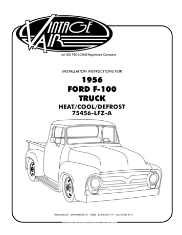
an ISO 9001:2015 Registered CompanyStreamline3-Knob Horizontal Panel, Anodized491223-RUACA/CFAN18865 Goll St. San Antonio, TX 78266Phone: 800-862-6658Sales: sales@vintageair.comTech Support: tech@vintageair.comwww.vintageair.com901223-RUA REV D 06/24/19 PG 1 OF 8
www.vintageair.comTable of ContentsCover. 1Table of Contents. 2Packing List/Parts Disclaimer. 3Control Panel Dimensions and Installation. 4Control Panel Installation (Cont.). 5Wiring Diagram. 6Operation of Controls. 7Packing List. 8Important Notice—Please ReadForcontrolMaximumPerformance,Air RecommendsThispanel isSystemdesigned toonly work with aVintageGen IV evaporatorunit equipped thewith Following:a 246204-PUAECU. Please confirm that your unit has the proper ECU prior to installing the control panel as shownServiceInfo:below.A replacementECU can be purchased from Vintage Air if needed.Evacuate the system for 35-45 minutes with system components (Drier, compressor, evaporator andcondenser) at a temperature of at least 85 F. On a cool day, the components can be heated with aheat gunOR by running the engine with the heater on before evacuating. Leak check and charge tospecifications.The Proper Amount of Refrigerant is Critical to Proper System Operation.Vintage Air Recommends Our System be Charged by Weight with a QualityCharging Station or Scale.Refrigerant Capacity for Vintage Air Systems:(For other systems, consult manufacturer’s guidelines)R134a SystemCharge with 1.8 lbs. (1 lb., 12 oz.) of refrigerant.Lubricant Capacities:New Compressor—No Additional Oil Needed.Used Compessor—Consult Vintage Air.2901223-RUA REV D 06/24/19, PG 2 OF 8
www.vintageair.comNo.1.2.Qty.11Part No.491222-RUA232007-VURPacking List:Control Panel Kit (491223-RUA)Streamline 3-KnobHorizontal, AnodizedDescriptionStreamline 3-Knob Horizontal Control Panel (Anodized)Gen IV Universal Control Harness** Before beginning installation, open all packages and check contents of shipment.Please report any shortages directly to Vintage Air within 15 days. After 15 days,Vintage Air will not be responsible for missing or damaged items.CA/CFAN21NOTE: Images may not depict actual parts and quantities.Refer to packing list for actual parts and quantities.3901223-RUA REV D 06/24/19, PG 3 OF 8
Control Panel ��Level This LineControl Panel Installation1. Select a suitable location for the control panel, considering heater control valve location, wiring harnesslength and operator convenience.2. After selecting a location for the control panel, mask the area 1 ½” (tall) x 4 ½” (wide).3. Using the dimensions provided above, mark or scribe the control panel opening location onto the dash.When you are certain that your dimensions and markings are correct, cut the dash to make the controlpanel opening. NOTE: Measure twice. Cut once. This opening MUST be a precise fit. Cut the openingundersize, and then file to fit. The mounting screws only hold the panel against the dash. They donot locate the panel laterally. If the opening is oversized, the panel may shift during use.4. Install the control panel face through the opening in the dash. Place the control panel PC board assemblybehind the dash, and secure it to the control panel face using the (4) 8-32 x 3/8” screws (See Figure 1 and2a, Page 5). NOTE: When tightening the control panel mounting screws, hand tighten until thescrew contacts the back side of the dash. Then, using a screwdriver, tighten an additional 1/2turn. Do not over tighten, as this may cause damage to the PC board or the dash.5. Plug the control panel wiring harness into the control panel and the ECU on the evaporator (See Figure 2,Page 5).6. Wire according to the wiring diagram on Page 6.4901223-RUA REV D 06/24/19, PG 4 OF 8
www.vintageair.comControl Panel Installation (Cont.)(4) ControlPanel PC BoardMounting Screws(4) ControlPanelMounting ScrewsThread IntoBack Side ofControl Panel FaceControlPanelPC BoardAssemblyOpeningin DashControlPanel FaceFigure 1CA/CFANControl PanelPC Board AssemblyNOTE: When using a Vintage Air supplied control panel,connect the tan wire from the Gen IV Evaporator wiringharness (232600-VUA) to the factory dash lights toenable panel backlighting.Control PanelPC Board AssemblyDashRear ViewThread IntoControlPanel FaceFigure 2Control PanelFaceECU232007-VURGen IV UniversalControl Harness5Figure 2aSnug AgainstBack Side of DashSide View901223-RUA REV D 06/24/19, PG 5 OF 8
Wiring REDWHT/REDWHT/YELWHT/GRNAC ANNUNCIATORBACKLIGHT POSBACKLIGHT NEGGND5V-SWTEMP WIPERMODE WIPERFAN WIPERPRE-WIREDVIEWED FROM WIRE SIDE232002-VUAA/C(IF USED)GEN IV ECUGEN IV WIRING DIAGRAMREV E, 10/6/2017TEMPMODEFANPROGRAM* DASH LAMP(IF USED)*** WIDE OPENTHROTTLESWITCH(OPTIONAL)** CIRCUITBREAKER30 AMPHEATERCONTROL VALVE* Dash Lamp Is Used Only With Type 232007-VUR Harness.** Warning: Always Mount Circuit Breaker As Close to the Battery As Possible. (NOTE: Wire BetweenBattery and Circuit Breaker Is Unprotected and Should Be Carefully Routed to Avoid a ShortCircuit).*** Wide Open Throttle Switch Contacts Close Only at Full Throttle, Which Disables A/CCompressor.6901223-RUA REV D 06/24/19, PG 6 OF 8
Operation of Controlswww.vintageair.comOn Gen IV systems with three lever/knob controls, the temperature control toggles between heat and A/Coperations. To activate A/C, move the temperature lever/knob all the way to cold and then back it off to the desiredvent temperature. For heat operation, move the temperature lever/knob all the way to hot and then adjust to thedesired vent temperature. The blower will momentarily change speed, each time you toggle between operations, toindicate the change. NOTE: For proper control panel function, refer to control panel instructions forcalibration procedure.Blower SpeedThis lever/knob controlsblower speed, fromOFF to HI.Mode ControlThis lever/knob controlsthe mode positions,from DASH to FLOORto DEFROST, with ablend in between.BlowerSpeedModeControlTemperature ControlThis lever/knob controlsthe temperature,from HOT to COLD.TemperatureControlCA/CFANA/C OperationBlower SpeedAdjust to desiredspeed.Mode ControlAdjust to desiredmode position(DASH positionrecommended).Temperature ControlFor A/C operation, adjust tocoldest position to engagecompressor (Adjust betweenHOT and COLD to reachdesired temperature).CA/CFANHeat OperationBlower SpeedAdjust to desiredspeed.Mode ControlAdjust to desiredmode position(FLOOR positionrecommended).Temperature ControlFor maximum heating, adjustto hottest position (Adjustbetween HOT and COLD toreach desired temperature).CA/CFANDefrost/De-fog OperationBlower SpeedAdjust to desiredspeed.Temperature ControlAdjust to desiredtemperature.Mode ControlAdjust to DEFROST position for maximum defrost, orbetween FLOOR and DEFROST positions for a bi-levelblend (Compressor is automatically engaged).7CA/CFAN901223-RUA REV D 06/24/19, PG 7 OF 8
www.vintageair.comNo.1.2.Qty.11Part No.491222-RUA232007-VURPacking List:Control Panel Kit (491223-RUA)Streamline 3-KnobHorizontal, AnodizedDescriptionStreamline 3-Knob Horizontal Control Panel (Anodized)Gen IV Universal Control HarnessChecked By:Packed By:Date:CA/CFAN21NOTE: Images may not depict actual parts and quantities.Refer to packing list for actual parts and quantities.8901223-RUA REV D 06/24/19, PG 8 OF 8
Install the control panel face through the opening in the dash. Place the control panel PC board assembly behind the dash, and secure it to the control panel face using the (4) 8-32 x 3/8" screws (See Figure 1 and 2a, Page 5). NOTE: When tightening the control panel mounting screws, hand tighten until the screw contacts the back side of the dash.
