Transcription
Erection and Safety ManualRevision NotesDate:October 04, 2016The following “Steel Building Erection Manual” pages have been revised effective immediately.1. Revision to page 34Last RevisionDate: 06/01/16By: JMMChanged cable hardware for 3/8” and 1/2”.
Erection and Safety ManualRevision NotesDate:July 07, 2016The following “Steel Building Erection Manual” pages have been revised effective immediately.2. Revision to page 54Last RevisionDate: 06/01/16By: JMMChanged mark numbers.
Erection and Safety ManualRevision NotesDate:June 01, 2016The following “Steel Building Erection Manual” pages have been revised effective immediately.3. Revisions to all pagesLast RevisionDate: 06/01/16By: JMMCreated new manual.
Erection and Safety ManualTable of ContentsSAFETY WARNINGINTRODUCTIONRECOMMENDED TOOLSSTANDARD PARTS1.0FOUNDATION1.1GENERAL INFORMATION ---------------- 131.2FOUNDATION CHECKING PROCEDURE ------------------------------------------------- 141.3ANCHOR BOLT SETTINGS ---------------- 161.4FRAMED OPENING CONCRETE NOTCH ------------------------------------------------- 171.5UNCURED CONCRETE WARNING ------ 182.0PRE-ERECTION2.1ACCESS TO --------------------------------- 192.2OFFLOADING CONSIDERATIONS ------- 202.3LIFTING EQUIPMENT ---------------------- 232.4CABLE TENSION VS. HOOK ---------- 242.5PRIMARY & SECONDARY STORAGE --- 262.6SHEETING & TRIM STORAGE ------------ 273.0PRIMARY & SECONDARY3.1GENERAL INFORMATION ---------------- 293.2STRUCTURAL FRAMING PRECAUTIONS ------------------------------------------------ 303.3LOCATION OF BUILDING PARTS -------- 313.4WIND BRACING INSTALLATION -------- 333.5CONNECTION BOLTS ---------------------- 36Last RevisionDate: 06/01/16By: JMMPage 1 of 120
Erection and Safety ManualTable of Contents3.6STANDING ---------------------------- 373.7PREPARING RAFTERS --------------------- 393.8RAISING RAFTERS -------------------------- 403.9PLUMBING THE FIRST ------------------ 413.10SECONDARY CONNECTIONS ------------ 433.11POST AND BEAM ENDWALLS ----------- 453.12REMAINING FRAMES --------------------- 463.13REMAINING SECONDARY ---------------- 473.14FRAMED OPENING TRIM --------- 484.0SHEETING & TRIM4.1GENERAL INFORMATION ---------------- 504.2“R” PANEL ----------------------------------- 514.3“PBR” PANEL -------------------------------- 524.4“PBU” ------------------------------------- 534.5ROOF AND WALL FASTENERS ----------- 544.6FASTENER ---------------------------- 554.7PROPER MASTIC INSTALLATION ------- 564.8PANEL PREPARATION --------------------- 574.9SQUARING THE GIRTS -------------------- 594.10WALL INSULATION ------------------------ 604.11SIDEWALL PANELS ------------------------- 634.12ENDWALL PANELS ------------------------- 654.13CORNER TRIM ------------------------------ 664.14EAVE --------------------------------------- 674.15SAFETY PRECAUTIONS FOR ROOFING WORK ----------------------------------------- 684.16ROOF INSULATION ------------------------ 714.17ROOF SHEETING SEQUENCE ------------ 74Last RevisionDate: 06/01/16By: JMMPage 2 of 120
Erection and Safety ManualTable of Contents4.18EAVE ---------------------------------- 754.19FIRST ROOF PANEL ------------------------ 774.20SIDELAP SEALANT -------------------------- 784.21EAVE ------------------------------------- 794.22INTERMEDIATE ROOF PANELS ---------- 804.23ENDLAP SEALANT -------------------------- 814.24TRANSLUCENT LIGHT PANEL ------------ 824.25FINAL ROOF PANEL ------------------------ 834.26UNIVERSAL RIDGE CAP ------------------- 844.27DIE-FORMED RIDGE CAP ----------------- 854.28TRIM INFORMATION ---------------------- - 874.30DOWNSPOUT ------------------------------- 884.31RAKE TRIM & PEAK --------------------- 894.32CORNER ----------------------------------- 90GENERAL WARNINGSGENERAL MAINTENANCEGLOSSARYLast RevisionDate: 06/01/16By: JMMPage 3 of 120
Erection and Safety ManualSafety WarningIMPORTANT!READ AND UNDERSTAND THIS PAGE BEFORE PROCEEDING WITHANY WORK OR FURTHER READINGSAFETY FIRSTARMSTRONG STEEL CORPORATION has a commitment to detail, design and engineer quality building components that aredesigned to meet the structural requirements of the building. However, the safety commitment and jobsite practices ofthe erector are beyond the control of ARMSTRONG.It is urgently recommended that the safe working conditions and accident prevention practices be the top priority on thejobsite and that local, state and federal safety and health standards always be followed to help ensure worker safety.These points cannot be stressed enough.Jobsite safety is a joint responsibility of all parties present on the jobsite, including owners, architects, engineers,contractors, subcontractors, delivery personnel, and employees of all the above, among others. All should be watchful toavoid hazards which might cause damage to property or injury to any person, including themselves.Always make certain all employees know the safest and most productive way of erecting a building along with emergencytelephone numbers, location of first aid stations and emergency procedures. Avoid working during inclement periodswhen personnel are at risk due to high winds, lightning, precipitations, etc. ARMSTRONG recommends daily meetingshighlighting safety procedures, the use of hard hats, rubber sole shoes for roof work, proper equipment for handlingmaterial and appropriate safety gear, including nets where necessary.This manual should be interpreted and administered with sound judgement consistent with good safety practices. Itsinformation is to be distributed to all workers on the jobsite. Where any doubt exists as to language or direction of thismanual, do not take a risk, “play it safe.”ALL DETAILS, RECOMMENDATIONS AND SUGGESTIONS IN THIS MANUAL ARE FORGENERAL GUIDELINES ONLY, AND NOT MEANT TO BE ALL INCLUSIVE. INDUSTRY ACCEPTEDINSTALLATION PRACTICES WITH REGARDS TO ALL AREAS NOT SPECIFICALLY DISCUSSED INTHIS MANUAL SHOULD BE FOLLOWED. ONLY EXPERIENCED, KNOWLEDGEABLE ERECTORSFAMILIAR WITH ACCEPTED PRACTICES SHOULD BE USED TO ASSURE A QUALITY PROJECT.Last RevisionDate: 06/01/16By: JMMPage 4 of 120
Erection and Safety ManualIntroductionARMSTRONG STEEL CORPORATION details, designs and engineers high quality, pre-engineered metal building packages.Quality erection is essential to complete the structure to the satisfaction of the customer.This manual has been prepared to help guide the erection process and reflects the techniques in use in the metal buildingindustry believed to be most representative of good erection practices. These procedures and methods are, by necessity,general in nature. The erector should always, especially in special circumstances, use proven and safe erection methods.This erection manual is intended as a support to the erection drawings that are furnished with each building. The erectiondrawings show the customer’s building as engineered and fabricated according to his/her requirements. The buildingerection drawings will always govern with regard to construction details and specific building parts. In case of conflictbetween this installation manual and the erection drawings, the erection drawings will take precedence. Contactcustomer service to resolve any matters not addressed.The information contained in this manual is believed to be reliable, however, ARMSTRONG disclaims any responsibility fordamages which may result from use of this manual since the actual erection operations and conditions are beyondARMSTRONG’s control. Only experienced, knowledgeable erectors with trained crews and proper equipment should beengaged to do the erection.It is emphasized that ARMSTRONG is only a manufacturer of metal buildings and components and is not engaged in theerection of its products. Opinions expressed by ARMSTRONG about erection practices are intended to present only a guideas to how the components could be assembled to create a building. The experience, expertise and skills of the erectioncrews as well as the equipment available for handling the materials determines the quality and safety of erection and theultimate customer satisfaction with the completed building.The MBMA’s “CODE OF STANDARD PRACTICE” shall govern with respect to the fabrication tolerances, erection methods,and all field work associated with the project in question.The erector should familiarize themselves with the contents of this document. Additional copies may be requested for anadditional cost.NOTE!COMPLETE SETS OF ERECTION DRAWINGS ARE FURNISHED WITH EVERY BUILDING. EACHPLAN IS SPECIALLY PREPARED FOR EACH INDIVIDUAL BUILDING AND SHOULD BE STRICTLYADHERED TO, THEREFORE ARMSTRONG DOES NOT FURNISH “AS-BUILT”DRAWINGS.FAMILIARIZE YOURSELF AND CREW WITH THESE DRAWINGS PRIOR TO START-UP.PREVIOUS SETS OF DRAWINGS MARKED “APPROVAL,” “PERMIT”OR “CONSTRUCTION” ARENOT TO BE REFERENCED FOR ERECTION.Last RevisionDate: 06/01/16By: JMMPage 5 of 120
Erection and Safety ManualRecommended ToolsWhen buying or renting tools for building erection, it is recommended that only industrial rated, top quality tools bepurchased. Experience shows that lighter duty tools, although cheaper initially, will not hold up satisfactorily, and in thelong run, will cost more, not only in repairs, but also in lost time. High speed drill bits are always recommended sincecarbon steel bits will not provide satisfactory service. Most erectors find that short jobber length bits are more economicaland rugged than standard length bits.Smaller hand tools are particularly difficult to maintain because of breakage, losses, theft, etc. Some erectors require theworkers on the crew to furnish their own tools in this category. Others issue the tools to individuals or foreman who areheld responsible and liable for them. Since work rules and customs differ according to localities, each erector shouldestablish a definite policy which is acceptable to his workers while protecting their property.Maintaining equipment and tools in a safe, clean condition reduces injuries, lowers replacement expense, and stimulatesworkers to take better care of equipment and greater pride in their work.SAFETY NOTE!MAKE CERTAIN THAT THE CORRECT TOOL IS AVAILABLE AND USED FOR EACH PHASE OFBUILDING ERECTION. IMPROPER TOOL USAGE MAY RESULT IN INJURY. ALL TOOLS SHOULD BEOSHA APPROVED FOR COMMERCIAL CONSTRUCTION USE. SAFETY FIRST!Last RevisionDate: 06/01/16By: JMMPage 6 of 120
Erection and Safety ManualRecommended ToolsRECOMMENDED TOOL LISTBall Peen HammerBox KnifeBridge ReamerBroom, PushBrush, WireCable, 1/2” DiameterCable ClampsCaulking Gun, Open BarrelChalk Line, 100 feet long with ChalkChannel LocksCable Chokers1/2” Cable, 6 feet long, eyes both ends5/8” Cable, 6 feet long, eyes both ends1/2” Cable, 10 to 14 feet long, eyes both endsChiselCome-a-longDollyDrift Pin (Spud Wrench, Barrel Pin, Bull Pin)Extension Cords16 gauge wire, 100 feet maximum cord length14 gauge wire, 200 feet maximum cord length12 gauge wire, 300 feet maximum cord lengthLaddersExtension, 20 to 40 feet longStep, 6 to 8 feet highLoad BindersPliers, Side CuttersPlumb BobPop Rivet Gun Manual or ElectricPunch, CenterRope, 1/2” – 5/8” Diameter, 40 to 60 feet long with hooksSawzallScaffold, with wheelsScrewdrivers, Flat and PhillipsSledge HammerSlings, Nylon, 4” wide, 10 to 12 feet longSnips, Aviation (1 Right-hand, 1 Left-Hand, 1 Straight Cut)Snips, Large (Bulldogs)Soapstone PencilSpirit Level, 6 feet longLast RevisionDate: 06/01/16By: JMMSpreader Bar, 20 feet long, 1 set of 3/4” Diameter,Center Eye, With HooksStaple Gun and StaplesStaple Gun, PlierSquare, FramingSquare, TryTape Measure20 to 30 feet long100 feet longTarps (Plastic Covers)Transit and Level RodVise Grips, Sheet MetalVise Grips, StandardVise Grips, Welding ClampWedge, SteelWrecking Bar (Crow Bar)WrenchesAdjustableOpen or Box End Wrenches, Various SizesSocket Wrench SetCutting Torch, with 100 foot hose, bottle cartPower Drill and Drill BitsHammer Drill with 6 bitsImpact Wrench and SocketsPower NibblerPower ShearsScrew Gun1700-2000 RPM Electric Screw Gun, with TorqueAdjustable Clutch for Self-Drillers Screws500-600 RPM Electric Screw Gun, with TorqueAdjustable Clutch for Self-Tapping ScrewsWelding UnitPage 7 of 120
Erection and Safety ManualStandard PartsUNIVERSAL CLIPCOLUMN BASE CLIPPart #BC-01JAMB BASE CLIPPart #BC-04WALKDOOR FRAME TO GIRT CLIPPart #'s8" Girts - BC-1310" Girts - BC-1412" Girts - BC-500Part #BC-05GIRT TO RAFTER CLIPCEE RAKE TO PURLIN CLIPPart #'sBC-15BC-16Last RevisionDate: 06/01/16By: JMMPage 8 of 120Part #'s8" Cee Rake/8" Purlins - BC-1810" Cee Rake/8" Purlins - BC-1912" Cee Rake/8" Purlins - BC-20
Erection and Safety ManualStandard PartsCEE RAKE RAFTER PEAK SPLICESHEETING CLIPPart #'s8" Cee Rake - BC-2510" Cee Rake - BC-2612" Cee Rake - BC-27EAVE STRUT PLATEPart #BC-42LINER FLANGE BRACE CLIPPart #BC-44BRACE PADPart #BC-46RAKE ANGLEBASE ANGLEPart #BC-50Last RevisionDate: 06/01/16By: JMMPage 9 of 120Part #L4x2
Erection and Safety ManualStandard PartsFRAMED OPENING COVER TRIMHEADER WRAP COVER TRIM35 16312818 BASED ON GIRT DEPTH812 BASED ON GIRT DEPTHCC31235 16Part #'s8" Girts - Q37010" Girts - AR37112" Girts - AR372STYLE EAVE CORNER CAPPart #'s8" Girts - AR38010" Girts - AR38112" Girts - AR382GUTTER/RAKE/HIGH EAVE CORNER CAP811677 1615 82116513 16611BEND DOWN 60 BEND DOWN 60 33 423 453 1643 16BEND DOWN 30 815 16COLOR: NEAR SIDEBEND DOWN 60 103 843 1653 16COLOR: NEAR SIDE53 16BEND DOWN 60 127 16BEND DOWN 60 15Part #'sLeft - AR961L - ShownRight - AR961R - OppositeRAKE TRIM CLOSURE CAP21166Part #AR962BASE TRIM91811 443 1613 467 81BEND DOWN 90 BEND DOWN 90 BEND DOWN 90 11 4COLOR: NEAR SIDEBEND DOWN 90 11 4121 485 16C58135 Part #'sLeft - AR963L - ShownRight - AR963R - OppositeLast RevisionDate: 06/01/16By: JMM31 4Page 10 of 120Part #BA
Erection and Safety ManualStandard PartsPRESS BROKE STRAIGHT DOWNSPOUT312PRESS BROKE DOWNSPOUT ELBOW 45 31244135 LENGTH77Part #DSE45Part #DSPRESS BROKE DOWNSPOUT ELBOW 90 312HEAD TRIM4C90 711 425 813 87Part #DSE90Part #HEOUTSIDE CORNER TRIMJAMB TRIM323 413 44C11 41C135 211 4135 35 8Part #JALast RevisionDate: 06/01/16By: JMMPage 11 of 120Part #OU
Erection and Safety ManualStandard PartsFLAT RIDGE CAP TRIMFLAT EAVE TRIM31 211121112CA 5A 1212ROOFSLOPECROOFSLOPEPart #Q190Part #UNSTYLE RAKE TRIMSTYLE HANG-ON GUTTERD167 8135 43 16C120 43 16B 35 835 8"C" BASED ONROOF SLOPE121 121 35 843 16413 411 4A 120 35 8135 120 371 471 4C120 43 1651 411 4ROOFSLOPE12Part #Q764Part #Q760STYLE LOW EAVE TRIMSTYLE HIGH EAVE TRIM67 869 1643 1635 871 4C121 120 ROOFSLOPE23 8C120 121 11 461235 823 435 8120 120 43 1643 1611 412ROOFSLOPE11 4A A Part #Q768Last RevisionDate: 06/01/16By: JMMPage 12 of 12011 4Part #Q772
Erection and Safety Manual1.0 Foundation1.1GENERAL INFORMATIONARMSTRONG recommends that all building foundations, including pier sizes, grade beams and floor slabs, be designed byan experienced local foundation engineer. The engineer can also recommend excavation procedures, drainage practices,form work, reinforcing steel requirements and concrete proportioning. This will assure proper designs, expedited workand reduced costs. All information that is required for the foundation engineer is in the Permit/Construction drawings.Proven construction techniques should be adhered to in the foundation work. The bottoms of all excavations should belevel and smooth, and care should be taken to prevent cave-ins when utilizing the walls of the excavations for concreteforms. Strict adherence to OSHA and other local codes or laws governing shoring of excavation to prevent accidental caveins is critical. Where the ground surface is not level, the bottoms of the foundations should be in steps coinciding with thepiers (as shown). Fill areas should be properly compacted to prevent settling cracks. Footing should extend below any fillmaterial.Take care to obtain a good finish on the floor slab and to maintain the correct elevation throughout the slab. Shrinkagecracks can be minimized by pouring the slab in alternate sections, “checker board fashion.” The outer corners of thefoundation walls and piers should be sharply formed with straight sides and level tops. This will allow neat seating andgood alignment of the base angle.Top of grade beamNatural groundSlabFooting or pier capGrade beams pouredagainst Earth sidesand bottomNOTE!ARMSTRONG DOES NOT PROVIDE ANCHOR BOLTS OR ENGINEERING FOR FOUNDATIONS.Last RevisionDate: 06/01/16By: JMMPage 13 of 120
Erection and Safety Manual1.0 Foundation1.2FOUNDATION CHECKING PROCEDUREThe importance of accurate foundation construction and anchor bolt settings cannot be overemphasized. Foundationerrors and misplacement of anchor bolts are among the most frequent and troublesome errors made in metal buildingconstruction. The following procedures and methods should help to minimize these costly errors and delays.TransitThis dimensionmust be equal1. To determine that the foundation is square, measure diagonal dimensions to be sure they are of equal length.2. To determine that the foundation is level, set up a transit and use a level rod to obtain the elevation at all columnsand post locations.Last RevisionDate: 06/01/16By: JMMPage 14 of 120
Erection and Safety Manual1.0 Foundation3. To determine that the anchor bolts are in the correct location, use the following procedure to check all anchorbolts against the “Anchor Bolt” drawing furnished by ARMSTRONG. All dimensions must be identical to ensureproper start-up. The procedure is as follows:A. Start at one end of the foundation and measure the distance to the centerline of each frame column andthe out to out dimensions of the foundation at both sides.B. Start at one side of the foundation and measure the distance to the centerline of each endwall columnand the out to out dimensions of the foundation at both ends and interior partitions.C. Measure the distance across the building between outside anchor bolts as shown on erection drawings.D. Measure the distance from outside of the foundation and from the centerline of each column to theanchor bolts.E. Measure the distance across, from center of column at edge of concrete, to next column opposite side,then for both columns.This dimensionmust be equal(E)Last RevisionDate: 06/01/16By: JMMPage 15 of 120
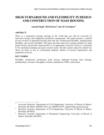
Erection and Safety Manual1.0 Foundation1.3ANCHOR BOLT SETTINGSIt is extremely important that anchor bolts be placed accurately in accordance with the anchor bolt plan. All anchor boltsshould be held in place with a template or similar means, so that they will remain plumb and in the correct location duringplacing of the concrete. Unless specified otherwise on the erection drawings, all anchor bolts are grade F1554 or A307. Alltemplates should be prepared in advance so they can be quickly nailed in place. For this reason, epoxy anchors orexpansion anchors should never be used. Whether you decide to have the optional concrete notch for your wall panels ornot, this will not affect the design of the foundation or any materials for the building. Drill air relief holes in the templateto allow trapped air to escape. When finishing or “floating” concrete, vibrate until wet concrete seeps through the top ofthe air relief holes. Check the concrete forms and anchor bolt locations prior to the pouring of the concrete. Prior topouring the concrete use duct tape to wrap and protect the anchor bolt threads. A person responsible to the buildershould check the concrete forms and the anchor bolt locations prior to the pouring of the concrete. A final check shouldbe made after the completion of the concrete work and prior to the steel erection. This will allow any necessarycorrections to be made, once ARMSTRONG is properly notified, and before the costly erection labor and equipmentarrives.Optional Notch mold(1 21" X 1 21")Air relief holes(1/8" diameter)Form boardDA ADTemplate(3/4" Plywood)BOptional Notch mold(1 21" X 1 21")Duplex nail(secures template)Template(3/4" Plywood)NOTE: Dimensions as specified byanchor bolt plans in erection drawings,and must be within 1/8" toleranceAnchor boltsOptional secondary template(Used to help keep anchor bolts straight and squared)(will remain embedded in concrete)Form boardSlab line(Finished floor)StakeStabilzed soilLast RevisionDate: 06/01/16By: JMMCPage 16 of 120
Erection and Safety Manual1.0 Foundation1.4FRAMED OPENING CONCRETE NOTCHIn order to keep water from entering your building, consider creating a sloping concrete notch in your foundation, at largeframed openings. When water hits your closed door, it will run down and normally back into your building. It is alwaysbest to verify with the door provider how far this notch should extend into your building. Normally 3” from the back ofyour door jamb is sufficient. This notch is also recommended to have some slope to it as well.Last RevisionDate: 06/01/16By: JMMPage 17 of 120
Erection and Safety Manual1.0 Foundation1.5UNCURED CONCRETE WARNINGRigid Frame ColumnEdge Of SlabUncured ConcreteNOTE!NEVER STORE MATERIAL OR BEGIN BUILDING ERECTION ON GREEN CONCRETE. ANCHORBOLTS MAY PULL LOOSE, CONCRETE SPALL (CHIP OUT ALONG EDGES) MAY OCCUR ANDEQUIPMENT MAY CRUSH OR CRACK SLAB. NORMAL PORTLAND CEMENT CONCRETE SHOULD CUREAT LEAST SEVEN DAYS AND HIGH-EARLY-STRENGTH CONCRETE AT LEAST THREE DAYS BEFORE THESTRUCTURAL COLUMNS ARE ERECTED. SPECIAL CIRCUMSTANCES MAY REQUIRE EVEN LONGERCURING PERIODS, SO CONSULT THE PROJECT ENGINEER, NOT ARMSTRONG ON FOUNDATIONQUESTIONS. BUILDING ON GREEN CONCRETE WILL ALSO CAUSE EXCESSIVE CONDENSATIONINSIDE OF THE BUILDING.Last RevisionDate: 06/01/16By: JMMPage 18 of 120
Erection and Safety Manual2.0 Pre-Erection2.1ACCESS TO SITEThe vehicle transporting your building parts will be hauling an 80-foot load, and must gain access to the building site fromthe adjacent highway or road. Such access should be studied and prepared in advance of arrival. All obstructions,overhead and otherwise, must be removed and the access route graveled or planked if the soil will not sustain the heavywheel loads. If a full size semi cannot safely navigate in and out of the jobsite, an alternate delivery address must bedesignated. Materials must be offloaded adjacent to the truck.Ensure there is enough room to physically perform the tasks required to erect the building. Application of sheeting andtrim can be expensive when there is not sufficient working space because of the proximity of adjacent buildings or otherobstructions.The availability of any required utilities should also be considered in advance. Take careful note of any overhead electriclines or other utilities to avoid hazards and damage (Notify your utility company when necessary).Develop a comprehensive safety awareness program in advance to familiarize the work force with the unique conditionsof the site, and the building materials, along with the appropriate “Safe Work” practices that will be utilized.NOTE!COMPLETE SETS OF ERECTION DRAWINGS ARE FURNISHED WITH EVERY BUILDING. EACHPLAN IS SPECIALLY PREPARED FOR EACH INDIVIDUAL BUILDING AND SHOULD BE STRICTLYFOLLOWED.FAMILIARIZE YOURSELF AND CREW WITH THESE DRAWINGS PRIOR TO START-UP.Last RevisionDate: 06/01/16By: JMMPage 19 of 120
Erection and Safety Manual2.0 Pre-Erection2.2OFFLOADING CONSIDERATIONSOffloading considerations are an important part of the erection procedure. This involves careful, safe and orderly storageof all materials. Detailed planning is required at the jobsite where storage space is restricted. Here, a planned separationof materials in the order of the erection process is necessary to minimize the costly double handling of materials. Whileset procedures are not possible in all cases, special attention should be given to the following items found on the nextpage.Load is consolidated or community freight. You are responsible for safely offloading all material that belongs to you, andmust safely replace any materials belonging to others back on the truck. Materials must be offloaded adjacent to thetruck. After the driver leaves, if necessary, move materials to the jobsite. You only have a 2 hour window to offload thematerial.NOTE!ARMSTRONG TRUCKS ARE LOADED TO MAXIMIZE EFFICIENCY, MAXIMIZE TRAILER WEIGHT,AND ENSURE SAFETY. UNFORTUNATELY, ARMSTRONG CAN NOT LOAD TRUCKS PER CUSTOMERREQUEST.NOTE!IN THE EVENT THAT A DISCREPANCY OR ERROR ARISES WITH MATERIALS SHIPPED FOR ANYPROJECT OR ON ERECTION DRAWINGS, THE ERECTOR/INSTALLER MUST NOTIFY ARMSTRONGPRI
ARMSTRONG STEEL CORPORATION details, designs and engineers high quality, pre-engineered metal building packages. Quality erection is essential to complete the structure to the satisfaction of the customer. This manual has been prepared to help guide the erection process and reflects the