Transcription
Touchmonitor User Guide1519L 15.6” LCD Desktop Touchmonitor1919L 18.5” LCD Desktop Touchmonitor(Optional Magnetic Stripe Reader Available)
Elo Touch Solutions15.6” and 18.5” LCD TouchmonitorOptional Magnetic Stripe ReaderUser GuideRevision CP/N E356416Elo Touch Solutions1-800-ELOTOUCHwww.elotouch.com
Copyright 2012 ELO Touch Solutions.All Rights Reserved.No part of this publication may be reproduced, transmitted, transcribed, stored in a retrievalsystem, or translated into any language or computer language, in any form or by any means,including, but not limited to, electronic, magnetic, optical, chemical, manual, or otherwisewithout prior written permission of ELO Touch Solutions.DisclaimerThe information in this document is subject to change without notice. ELO Touch Solutionsand its Affiliates makes no representations or warranties with respect to the contentsherein, and specifically disclaims any implied warranties of merchantability or fitnessfor a particular purpose. ELO Touch Solutions reserves the right to revise this publicationand to make changes from time to time in the content hereof without obligation of ELOTouch Solutions to notify any person of such revisions or changes.Trademark AcknowledgmentsAccuTouch, ELO (logo), ELO Touch Solutions, and IntelliTouch, are trademarks of the ELO TouchSolutions. Windows is a trademark of the Microsoft group of companies. Other product namesmentioned herein may be trademarks or registered trademarks of their respective companies. ELOTouch Solutions claims no interest in trademarks other than its own.iii
Table of ContentsChapter 1IntroductionChapter 4Troubleshooting526Solutions to Common Problems .26Product Description .5Precautions.5Appendix AChapter 2Installation and SetupNative Resolution .276Unpacking Your Touchmonitor .6Appendix BAssembling the stand plate .8Interface Connection .9Speakers and Audio .9MSR Interface connection (Optional) .10Product Overview .11Main Unit .11Rear View .11Mounting the Display .12Rear Mounting Using the VESA Interface .13VESA Mounting Options.13Installing the Driver Software.14Installing the Serial Touch Driver (not applicableto Acoustic Pulse Recognition andTouchmonitor Safety .29Care and Handling of Your Touchmonitor .30Appendix CTouchmonitor Specifications .3115.6" LCD Touchmonitor (ET1519L) Dimensions .3418.5" LCD Touchmonitor (ET1919L) Dimensions .35Regulatory Information 36Warranty 39Projected-Capacitive monitor) .15Installing the Serial Touch Driver for Windows 7,Windows Vista, Windows XP, Windows 2000, ME,Windows 98/95 and NT 4.0 .16Installing the Serial Touch Driver for Windows 3.1and MS-DOS .16Installing the USB Touch Driver .17Installing the USB Touch Driver for Windows 7,Windows Vista, Windows XP, Windows 2000, ME,and Windows 98.17Installing APR USB Touch Driver forWindows 7, Windows VISTA andWindows XP .17Chapter 3Operation18About Touchmonitor Adjustments .18Bottom Panel Controls.19Controls and Adjustment .20OSD Menu Functions .20OSD Lock/Unlock .20OSD Control Options.21Preset Modes .22Power Management System.23Display Angle.23IntelliTouch Plus Touch Technology .24Projected-Capacitive Touch Technology .25Gesture Support .25v
C HAPTE R1INTRODUCTIONProduct DescriptionYour new 1519/1919L touchmonitor combines the reliable performance of touch technologywith the latest advances in LCD display design. This combination of features creates a naturalflow of information between a user and your touchmonitor.This LCD monitor incorporates a 15.6” or 18.5” color active matrix thin-film-transistor (TFT)liquid crystal display to provide high quality display performance. A maximum resolution ofWXGA 1366 x 768 is well-suited for displaying both graphics and images. Other features thatenhance the performance of this LCD touchmonitor are Plug & Play compatibility, OSD (OnScreen Display) controls, an optional magnetic strip reader (MSR), and Elo’s unique zero-bezelAcoustic Pulse Recognition (APR) touchscreen. In addition, the 1519/1919L is easilyconfigurable for either portrait or landscape orientation.PrecautionsFollow all warnings, precautions and maintenance procedure as recommended in this user’smanual to maximize the life of the touch monitor. See Appendix B for more information ontouchmonitor safety.1-5
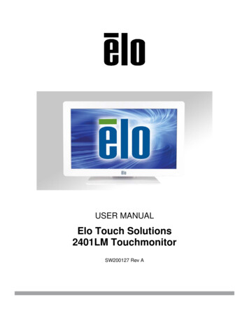
C HAPTE R2INSTALLATION AND SETUPThis chapter discusses how to install the 1519L/1919L LCD touchmonitor and the driversoftware.Unpacking Your TouchmonitorCheck that the following items are present and in good condition:LCD monitorVGA cableUSB cableAudio cableElo QuickStartCDSoftwareCD and Quick Install GuidePower BrickSerial Cable(not included with APR model)2-6
Power cable for North America modelsUSA/UL Power cablePower cable for European modelsEurope/VDE power cableUK power cablePower cable for Japan modelsJapanese/PSE power cableAdapter/TerminalPower cable for Asia modelsandandororChina/CCC power cable Taiwan/BSMI power cableKorea/KC power cablePower cable for Worldwide modelsUSA/UL Power cableEurope/VDE power cable2-7
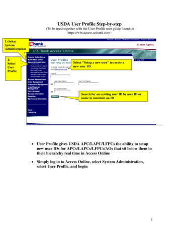
Assembling the stand platePushing the stand plate toward the stand untill it is tight, then fasten the stand plate usingcaptive screw.2-8
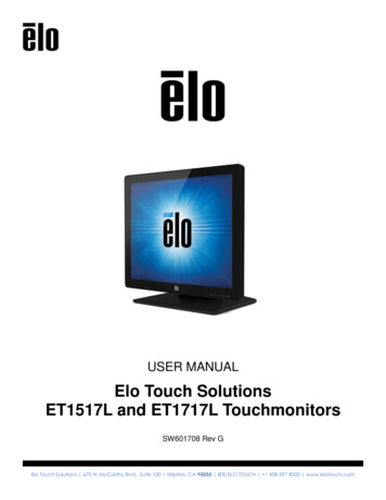
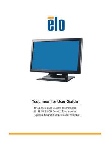
Interface ConnectionNote:Before connecting the cables to your touchmonitor and PC, be sure that the computer andtouchmonitor are turned off.Headphone Cable1232Serial Cable4Audio CableVGA CableUSB CablePower Brick1. Connect DC cable of the power brick to the monitor and the other end through AC powercable to the AC outlet.2. Connect one end of either the touchscreen serial (RS232) cable or the touch screen USBcable (but not both) to the rear side of the computer and the other end to the LCD monitor.Tighten by turning the two thumb screws clockwise to ensure proper grounding.3. Connect one end of the VGA cable to the rear side of computer and the other to the LCDmonitor. Tighten by turning the two thumb screws clockwise to ensure proper grounding.4. Connect one end of the audio cable to the rear side of computer and the other to the LCDmonitor.5. Facing the monitor, press the power button located on the underside of the botom-rightcorner of the monitor.Speakers and AudioThe touchmonitor includes two built-in speakers. To use the speakers, plug in the audio cableto the Audio Input port and connect the other end to your computer.To use headphones, plug in the headphones to the Audio Output port shown above. Whenheadphones are connected, the sound plays through the headphones only.The volume and muting of the sound can be adjusted by using the “Audio” choice from theOn-Screen Display (OSD) Control panel menu as described on page 3-21.2-9
Magnetic Stripe Reader (MSR) Interface Connection (optional)If the MSR is installed on the monitor, plug the USB cable from the MSR directly to the PC.No drivers are required to be loaded.To change the MSR function mode from keyboard emulation to HID, load the “MSR CHANGEMODE.EXE” utility from the enclosed TouchTools CD or go online to www.elotouch.com todownload this utility.Note:MSR function mode can be changed to HID mode from keyboard emulation mode and back usingthe “MSR CHANGE MODE.EXE” utility.2-10
Product OverviewMain UnitRear ViewKensingtonTMLockThe KensingtonTM lock is a security device that prevents theft. To find out more about this security device, go to http://www.kensington.com.2-11
Mounting the DisplayYour medically certified touchscreen display conforms to the VESA Flat Panel MonitorPhysical Mounting Interface (FPMPMI) standard. The FPMPMI standard defines a physicalmounting interface for flat panel displays. Your display conforms to the correspondingstandards for flat panel display mounting devices, such as for walls and table arms. The VESAmounting interface is located on the back of your touchscreen display and is pre-connected tothe pedestal.ET1919LM111ET1519LM1Figure 2-1 : VESA mounting interface location, pedestal removed1 Screw location, M4 Phillips, 4Note:2-12You will need a Phillips screwdriver to mount the display or remove the pedestal.
Rear Mounting Using the VESA Interface1 If the display is already connected to a pedestal, remove the four screws that connect thepedestal to the display (refer to Figure2-1 , item 1 ). Separate the pedestal from the display.2 Reinstall the four screws into the VESA interface mount. Ensure that the monitor ispositioned with the correct side up.3 Mount the monitor to the wall according to the template shown in Figure 2-2. Route thecables through the cable access opening.11Figure 2-2: Rear mount template (not to scale)ET1519LMET1919LMVESA Mounting OptionsThe following companies provide VESA mounting devices compatible with your n.comInnovative Office rod.comMRI800-688-2414www.mediarecovery.com2-13
Installing the Driver SoftwareELO Touch Solutions provides driver software that allows your touchmonitor to work with yourcomputer. Drivers are located on the enclosed CD-ROM for the following operating systems: Windows 7 Windows Vista Windows XP Windows 2000Windows MeWindows 98Windows 95Windows NT 4.0 Windows 3.1 MS-DOSAdditional drivers and driver information for other operating systems are available on the ELOTouch Solutions web site at www.elotouch.com.The ELO touchmonitor is plug-and-play compliant. Information on the video capabilities ofyour touchmonitor is sent to your video display adapter when Windows starts. If Windowsdetects your touchmonitor, follow the instructions on the screen to install a generic plug-andplay monitor.Refer to the following appropriate section for driver installation instructions.Depending upon whether you connected the serial communication cable or the USBcommunication cable, only the serial driver or the USB driver should be installed.2-14
Installing the Serial Touch Driver (not applicable to AcousticPulse Recognition and Projected-Capacitive monitor)Installing the Serial Touch Driver for Windows 7, Windows Vista,Windows XP, Windows 2000, 98/95, ME and NT4.0NOTE: For Windows 2000 and NT4.0 you must have administrator access rights to install the driver.Make sure the serial connector (RS232) is plugged into the monitor and an open com port onthe PC.1 Insert the ELO CD-ROM in your computer's CD-ROM drive.2 If the AutoStart feature for your CD-ROM drive is active, the system automatically detectsthe CD and starts the setup program.3 Follow the directions on the screen to complete the driver setup for your version ofWindows.4 If the AutoStart feature is not active:5678Click Start Run.Click the Browse button to locate the EloCd.exe program on the CD-ROM.Click Open, then OK to run EloCd.exe.Follow the directions on the screen to complete the driver setup for your version ofWindows.2-15
Installing the Serial Touch Driver for Windows 3.1 and MS-DOSYou must have a DOS mouse driver (MOUSE.COM) installed for your mouse if you wish tocontinue using your mouse along with your touchmonitor in DOS.To install Windows 3.x and MS-DOS touch driver from Windows 98/95, follow the directionsbelow:1 Insert the CD-ROM in your computer’s CD-ROM drive.2 From DOS, type d: and press the Enter key to select the CD-ROM (your CD-ROM drivemay be mapped to a different drive letter).3 Type cd\elodos w31 to change to the correct directory.4 Type Install and press Enter to start the installation.5 Calculate the touchscreen.2-16
Installing the USB Touch DriverInstalling the USB Touch Driver for Windows 7, Windows Vista, Windows XP,Windows 2000, ME and Windows 98.1 Insert the ELO CD-ROM in your computer’s CD-ROM drive.If Windows 2000 or Windows 98 starts the Add New Hardware Wizard, do the following:2 Choose Next. Select “Search for the best driver for your device (Recommended)” andchoose Next.3 When a list of search locations is displayed, place a checkmark on “Specify a location” anduse Browse to select the \EloUSB directory on the ELO CD-ROM.4 Choose Next. Once the ELO USB touchscreen driver has been detected, choose Next again.5 You will see several files being copied. Insert your Windows 98 cd if prompted. ChooseFinish.If Windows 2000 or Windows 98 does not start the Add New Hardware Wizard, do thefollowing:NOTE: For Windows 2000 you must have administrator access rights to install the driver.1 Insert the ELO CD-ROM in your computer’s CD-ROM drive. If the AutoStart feature foryour CD-ROM drive is active, the system automatically detects the CD and starts the setupprogram.2 Follow the directions on the screen to complete the driver setup for your version ofWindows.If the AutoStart feature is not active:1 Click Start Run.2 Click the Browse button to locate the EloCd.exe program on the CD-ROM.3 Click Open, then OK to run EloCd.exe.4 Follow the directions on the screen to complete the driver setup for your version ofWindows.Installing APR USB Touch Driver for Windows 7, Windows VISTA andWindows XPInsert the ELO APR CD-ROM in your computer’s CD-ROMdriver.Follow the directions on the screen to complete the APR 3.1 driver setup for your version ofWindows. Do not plug USB cable until software is fully loaded. When finished, plug USBcable and alignment data is transferred.Note:For the latest driver, go to elotouch.com and download it from the driver download section.2-17
C HAPTE R3OPERATIONAbout Touchmonitor AdjustmentsYour touchmonitor will not likely require adjustment. However, variations in video output andapplication may require adjustments to the touchmonitor to optimize the quality of the display.For best performance, the input video resolution should be the touchmonitors native resolution,1366 x 768. Use the Display control panel in Windows to choose 1366 x 768 resolution.Operating in other resolutions will degrade video performance. For further information, pleaserefer to Appendix A.All adjustments made to the controls are automatically memorized. This feature saves you fromhaving to reset the choices every time the touchmonitor is unplugged or powered off and on. Ifthere is a power failure, the touchmonitor settings will not default to the factory specifications.3-18
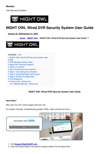
Bottom Panel ControlsSELECTMENUAudio OutputSELECT54MENU321Control1 Menu/ExitFunctionDisplay/Exits the OSD menus.21. Enter Luminance of the OSD.2. Increase value of the adjustment item.3. Move OSD selection upward.31. Enter Audio of the OSD.2. Decrease value of the adjustment item.3. Move OSD selection downward .4 Select1. Auto adjust function.2. Select the adjustment item from the OSD menu.5 Power SwitchSwitch the power of the monitor.3-19
Controls and AdjustmentOn Screen Display (OSD) Menu FunctionsTo Display and Select the OSD Functions:1. Press the Menu key to activate the OSD menu.2. Use or to move upward or downward through the menu. Press the “Select” key,execute the function or enter the sub-menu.3. To quit the OSD screen at any time during the operation, press the Menu key. If no keys arepressed for a short time period, the OSD automatically disappears.NOTE: The OSD screen will disappear if no input activities are detected for at a minimum of 15 secondsor depending on how long the timer is set via the OSD menu. The time ranges from 5 seconds to60 seconds.On Screen Display (OSD) Lock/UnlockThe OSD feature can be locked and unlocked. The monitor is shipped in the unlocked position.To lock the OSD:1. Press the Menu button and button simultaneously until a window appears displaying“OSD Unlocked”. Continue to hold the buttons until the window toggles to “OSD Locked”.2. To unlock the the Power Locking Feature, repeat the procedure until the “OSD Unlocked” isdisplayed.To lock the power:1. Press the menu and button simultaneously until a window displaying “Power unlocked”appears. Continue to hold the buttons until the “Power Locked”.2. To unlock the power repeat the procedure until the “Power Unlocked” is displayed.3-20
On Screen Display(OSD) Control rastImage riptionSelect “Auto-Adjust” to enable this function. The Auto-Adjustwill automatically adjust V-Position, H-Position, Clock andPhase.Increases or decreases brightnessIncreases or decreases contrastMoves the screen left or rightMoves the screen up or downThe dot clock is fine-adjusted after auto adjust.Increases or decreases the video noise of the image after anauto adjustment is made.Press or to select 9300, 6500, 5500, 7500 and USER.Only when selecting USER can you make adjustments to theR/G/B content values.Audio.Mute.VolumeOSD.OSD H-Position.OSD V-Position.OSD TimeoutEnable/Disable audio mute.Increase or decrease audio volume.Moves the OSD position horizontally on the screen. When thebutton is pressed, the OSD control menu will move to theright side of the screen. Likewise, when thebutton ispressed, the OSD control menu will move to the left side.Moves the OSD position vertically on the screen. When thebutton is pressed, the OSD control menu will move to thetop side of the screen. Likewise, when the button is pressed,the OSD control menu will move to the lower side.Adjusts the amount of time of the OSD menu is displayed.LanguageSelect from English, French, Italian, German, Spanish,Japanese, Traditional Chinese and Simplified Chinese.RecallMiscellaneous.Aspect ratio.Fill screenReturns the monitor to its default settings.Fill to Aspect ratio.SharpnessNo matter what LCD aspect ratio, scales video so it fills theLCD with no over or under scan. Change video aspect ratio.Sets the height of video equal to the height of LCD. VideoAspect ratio is preserved. Black bars on left and right side ofLCD screen may appear.Adjusts sharpness of video signals on a scale from 1 to 5 using4 discrete steps.ExitExits the OSD display.3-21
Preset ModesTo reduce the need for adjustment for different modes, the monitor has default setting modesthat are most commonly used as given in the table below. If any of these display modes aredetected, the monitor automatically adjusts the picture size and centering. When none of themodes are matched, the user can store their preferred modes in the user modes. The monitoris capable of storing up to 7 user modes. The only condition to store as a user mode is the newdisplay information which must have 1 KHz difference for horizontal frequency or 1 Hz forvertical frequency or the sync signal polarities are different from the default modes.Resolution3-22Vertical Frequency720 x 35070Hz (may not display at full screen)720 x 40070Hz640 x 48060 / 72 / 75Hz800 x 60056 / 60 / 72 / 75Hz832 x 62475Hz1024 x 76860 / 70 / 75Hz1280 x 80060Hz1280 x 96060Hz1280 x 102460 / 75Hz1360 x 76860Hz1366 x 76860Hz1440 x 90060Hz1600 x 120060Hz1680 x 105060Hz
Power Management SystemModeOnSleepOffPowerConsumption (12VDC input) 42W 2W 1WIt is recommended to switch the monitor off when it is not in use for a long period of time.NOTE: Complies to VESA Power Management (DPM) standards. To activate the monitor, press any keyon the keyboard or move the mouse or touch the touchscreen. In order for the touchscreen to bringthe monitor from the DPM system, the touchscreen function must be fully operational.Display AngleFor viewing clarity, the LCD can tilt forward (up to -5 degrees) or backward (up to 90 degrees.)CAUTIONIn order to protect the LCD, be sure to hold the base when adjusting the LCD and do nottouch the screen.3-23
IntelliTouch Plus Touch TechnologyWhen connected to Windows 7 computers, the touchmonitor can report 2 simultaneous touches.The IntelliTouch Plus touchscreen can be re-calibrated to your displayed video image, ifneeded, through the Calibration function in the ELO driver control panel.The IntelliTouch Plus driver will only support multiple monitor if they are all using theIntelliTouch Plus touch technology.To use multiple IntelliTouch Plus monitors, double click on the EloConfig desktop shortcut toopen up the ELO Touchscreen Configuration screen.Select “Match Touch to Display ” to calibrate multiple monitors.3-24
Projected-Capacitive Touch TechnologyWhen connected to Windows 7 computers, the touchmonitor can report 2 simultaneous touches.When connected to Windows XP computers, the touchmonitor reports single touches.No additional drivers are required for this technology to work, it uses Windows HID drivers.No calibration is required for this technology.Gesture SupportThe IntelliTouch Plus and Projected-Capacitive touch technologies enable several gestures thatsupport single and multiple contacts. Refer to the Microsoft Website http://msdn.microsoft.com/en-us/library/dd940543 on the various gestures that are supported in Windows 7.3-25
C HAPTE R4TROUBLESHOOTINGIf you are experiencing trouble with your touchmonitor, refer to the following table. If theproblem persists, please contact your local dealer or the ELO’service center.Solutions to Common ProblemsProblemThe monitor does not respondwhen turning on the system.Suggestion(s)1. Check that the monitor’s Power Switch is on.2. Turn off the power and check the monitor’s DC power cordand signal cable for proper connection.Characters on the screen are dimRefer to the About Touchmonitor Adjustments section toadjust the brightness.The video is blank1. During operation, the monitor screen may automatically turnoff as a result of the Power Saving feature. Press any key to seeif the screen reappears.2. Refer to the About Touchmonitor Adjustments section toadjust the brightness.4-26Screen flashes when initializedTurn the monitor off then turn it on again.“Out of Range” displayReconfigure the resolution of your computer to make one of themonitor’s supported video mode (see Appendix C).See Appendix Afor more information on resolution.Touch doesn’t workMake sure the touch cable is securely attached at both ends.
APPEN D I XANATIVE RESOLUTIONThe native resolution of a monitor is the resolution level at which the LCD panel is designed toperform best. For the LCD touchmonitor, the native resolution is 1366 x 768 for the 15.6 inchand 18.5 inch size. In almost all cases, screen images look best when viewed at their nativeresolution. The resolution setting of a monitor can be lowered but not increased.Input Video640 x 480 (VGA)800 x 600 (SVGA)1024 x 768 (SVGA)1519L/1919L monitorTransforms input format to 1366 x 768Transforms input format to 1366 x 768Transforms input format to 1366 x 7681366 x 768 (WXGA)1360 x 768Displays in Native ResolutionDisplays with scalingThe native resolution of an LCD is the actual number of pixels horizontally in the LCD by thenumber of pixels vertically in the LCD. LCD resolution is usually represented by the followingsymbols:VGA640 x 480SVGAXGASXGAUXGA800 x 6001024 x 7681280 x 10241600 x 1200WXGA, avgSXGAWXGA, maxWXGA WSXGA 1280 x 8001280 x 9601366 x 7681440 x 9001680 x 1050A-27
As an example, a SVGA resolution LCD panel has 800 pixels horizontally by 600 pixelsvertically. Input video is also represented by the same terms. XGA input video has a format of1024 pixels horizontally by 768 pixels vertically. When the input pixels contained in the videoinput format match the native resolution of the panel, there is a one to one correspondenceof mapping of input video pixels to LCD pixels. As an example, the pixel in column 45 androw 26 of the input video is in column 45 and row 26 of the LCD. For the case when the inputvideo is at a lower resolution than the native resolution of the LCD, the direct correspondencebetween the video pixels and the LCD pixels is lost. The LCD controller can compute thecorrespondence between video pixels and LCD pixels using algorithms contained on itscontroller. The accuracy of the algorithms determines the fidelity of conversion of video pixelsto LCD pixels. Poor fidelity conversion can result in artifacts in the LCD displayed image suchas varying width characters.A-28
APPEN D I XBTOUCHMONITOR SAFETYThis manual contains information that is important for the proper setup and maintenance ofyour touchmonitor. Before setting up and powering on your new touchmonitor, read throughthis manual, especially Chapter 2 (Installation), and Chapter 3 (Operation).1 To reduce the risk of electric shock, follow all safety notices and never open thetouchmonitor case.2 Turn off the product before cleaning.3 The slots located on the sides and top of the touchmonitor case are for ventilation. Do notblock or insert anything inside the ventilation slots.4 It is important that your touchmonitor remains dry. Do not pour liquid into or onto yourtouchmonitor. If your touchmonitor becomes wet do not attempt to repair it yourself.B-29
Care and Handling of Your TouchmonitorThe following tips will help keep your touchmonitor functioning at the optimal level. To avoid risk of electric shock, do not disassemble the brick power supply or display unitcabinet. The unit is not user serviceable. Remember to unplug the display unit from thepower outlet before cleaning. Do not use alcohol (methyl, ethyl or isopropyl) or any strong dissolvent. Do not use thinneror benzene, abrasive cleaners or compressed air. To clean the display unit cabinet, use a cloth lightly dampened with a mild detergent. Avoid getting liquids inside your touchmonitor. If liquid does get inside, have a qualifiedservice technician check it before you power it on again. Do not wipe the screen with a cloth or sponge that could scratch the surface. To clean the touchscreen, use window or glass cleaner. Put the cleaner on a clean cloth andwipe the touchscreen. Never apply the cleaner directly to the touchscreen.WarningThis product consists of devices that may contain mercury, which must be recycled or disposedof in accordance with local, state, or federal laws. (Within this system, the backlight lamps inthe monitor display contain mercury.)Waste Electrical and Electronic Equipment (WEEE) DirectiveIn the European Union, this label indicates that this product should not be disposed of withhousehold waste. It should be deposited at an appropriate facility to enable recovery andrecycling.B-30
APPEN D I XCTECHNICAL SPECIFICATIONSC-31
Touchmonitor SpecificationsModelLCD DisplayDisplay SizePixel PitchNative ResolutionDisplay ModeContrast RatioBrightnessResponse TimeDisplay ColorViewing AngleInput VideoSignal TypeSyncConnectorBottom ControlsSpeakersAudio Input ConnectorHeadphone Output connectorOSDPlug & PlayTouch PanelPower AdapterOperating ConditionsStorage ConditionsDimensions (HxWxD)Weight TemperatureHumidityAltitude1519L15.6” TFT Active Matrix Panel344.232 (H) x 193.536 (V) mm0.252 (H) x 0.252 (V) mm1366 x 768720 x 350 (70Hz) - (may not display at full screen)720 x 400 (70Hz)640 x 480 (60 / 72 / 75Hz)800 x 600 (56 / 60 / 72 / 75Hz)832 x 624 (75Hz)1024 x 768 (60 / 70 / 75Hz)1280 x 800 (60Hz)1280 x 960 (60Hz)1280 x 1024 (60 / 75Hz)1360 x 768 (60Hz)1366 x 768 (60Hz)1440 x 900 (60Hz)1600 x 1200 (60Hz)1680 x 1050 (60Hz)500 : 1 (typical)LCD Monitor: typical 250 Cd/m2; Min 210 Cd/m2AccuTouch: typical 200 Cd/m2; Min 157.5 Cd/m2IntelliTouch: typical 225 Cd/m2; Min 178.5 Cd/m2Acoustic Pulse Recognition: typical 225 Cd/m2; Min 178.5 Cd/m2Projected-Capacitive: typical 225 Cd/m2; Min 185 Cd/m2IntelliTouch Plus: typical 225 Cd/m2; Min 179 Cd/m2Tr Tf 8ms (Typ.)16.7MooVertical -20 / 45oHorizontal 45R.G.B. Analog 0.7Vp-p, 75 ohmTTL Positive or Negative, Sync on green or Composite Sync.Mini D-Sub 15 pinMenu,, , Select, PowerTwo 2W internal speakers3.5mm TRS jackTwo 3.5m TRS jackContrast, Brightness, H-Position, V-Position,Color Temperature, Phase, Clock, OSD Time, Recall,Language: English, French, Italian, German, Spanish, Japanese,Traditional Chinese and Simplified ChineseDDC 2BAccuTouch /IntelliTouch/Acustic Pulse RecognitionProjected-Capacitive/IntelliTouch PlusInput: AC 100-240V, 50-60Hz , Output: DC 12V/4.16Aoo0 C 40 C20% 80% (No Condensation)0 to 3,658moo-20 C 50 C10% 90% (No Condensation)0 to 12,192m383.05 x 276.5 x 213.2mm/ 406.21 x 276.5 x 213.2mm (with MSR)5.2KgArgentina S-Mark, UL, CE, FCC, VCCI, C-Tick, CCC,ICES-003, China RoHS
Touchmonitor SpecificationsModelLCD DisplayDisplay SizePixel PitchNative ResolutionDisplay ModeContrast RatioBrightnessResponse TimeDisplay ColorViewing AngleInput VideoSignal TypeSyncConnectorBottom ControlsSpeakersAudio Input ConnectorHead
Connect one end of either the touchscreen serial (RS232) cable or the touch screen USB cable (but not both) to the rear side of the computer and the other end to the LCD monitor. . ELO Touch Solutions provides driver software that allows your touchmonitor to work with your computer. Drivers are located on the enclosed CD-ROM for the following .