Transcription
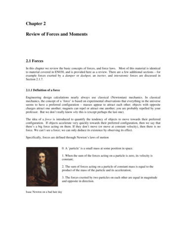
Chapter 2Review of Forces and Moments2.1 ForcesIn this chapter we review the basic concepts of forces, and force laws. Most of this material is identicalto material covered in EN030, and is provided here as a review. There are a few additional sections – forexample forces exerted by a damper or dashpot, an inerter, and interatomic forces are discussed inSection 2.1.7.2.1.1 Definition of a forceEngineering design calculations nearly always use classical (Newtonian) mechanics. In classicalmechanics, the concept of a force’ is based on experimental observations that everything in the universeseems to have a preferred configuration – masses appear to attract each other; objects with oppositecharges attract one another; magnets can repel or attract one another; you are probably repelled by yourprofessor. But we don’t really know why this is (except perhaps the last one).The idea of a force is introduced to quantify the tendency of objects to move towards their preferredconfiguration. If objects accelerate very quickly towards their preferred configuration, then we say thatthere’s a big force acting on them. If they don’t move (or move at constant velocity), then there is noforce. We can’t see a force; we can only deduce its existence by observing its effect.Specifically, forces are defined through Newton’s laws of motion0. A particle’ is a small mass at some position in space.1. When the sum of the forces acting on a particle is zero, its velocity isconstant;2. The sum of forces acting on a particle of constant mass is equal to theproduct of the mass of the particle and its acceleration;3. The forces exerted by two particles on each other are equal in magnitudeand opposite in direction.Isaac Newton on a bad hair day
The second law provides the definition of a force – if a mass m has acceleration a, the force F acting on itisF maOf course, there is a big problem with Newton’s laws – what do we take as a fixed point (and orientation)in order to define acceleration? The general theory of relativity addresses this issue rigorously. But forengineering calculations we can usually take the earth to be fixed, and happily apply Newton’s laws. Inrare cases where the earth’s motion is important, we take the stars far from the solar system to be fixed.2.1.2 Causes of forceForces may arise from a number of different effects, including(i) Gravity;(ii) Electromagnetism or electrostatics;(iii) Pressure exerted by fluid or gas on part of a structure(v) Wind or fluid induced drag or lift forces;(vi) Contact forces, which act wherever a structure or component touches anything;(vii) Friction forces, which also act at contacts.Some of these forces can be described by universal laws. For example, gravity forces can be calculatedusing Newton’s law of gravitation; electrostatic forces acting between charged particles are governed byCoulomb’s law; electromagnetic forces acting between current carrying wires are governed by Ampere’slaw; buoyancy forces are governed by laws describing hydrostatic forces in fluids. Some of theseuniversal force laws are listed in Section 2.6.Some forces have to be measured. For example, to determine friction forces acting in a machine, you mayneed to measure the coefficient of friction for the contacting surfaces. Similarly, to determineaerodynamic lift or drag forces acting on a structure, you would probably need to measure its lift and dragcoefficient experimentally. Lift and drag forces are described in Section 2.6. Friction forces arediscussed in Section 12.Contact forces are pressures that act on the small area of contact between two objects. Contact forces caneither be measured, or they can be calculated by analyzing forces and deformation in the system ofinterest. Contact forces are very complicated, and are discussed in more detail in Section 8.2.1.3 Units of force and typical magnitudesIn SI units, the standard unit of force is the Newton, given the symbol N.The Newton is a derived unit, defined through Newton’s second law of motion – a force of 1N causes a 1kg mass to accelerate at 1 ms 2 .The fundamental unit of force in the SI convention is kg m/s2In US units, the standard unit of force is the pound, given the symbol lb or lbf (the latter is an abbreviationfor pound force, to distinguish it from pounds weight)A force of 1 lbf causes a mass of 1 slug to accelerate at 1 ft/s2
US units have a frightfully confusing way of representing mass – often the mass of an object is reportedas weight, in lb or lbm (the latter is an abbreviation for pound mass). The weight of an object in lb is notmass at all – it’s actually the gravitational force acting on the mass. Therefore, the mass of an object inslugs must be computed from its weight in pounds using the formulam (slugs) W (lb)g (ft/s 2 )where g 32.1740 ft/s2 is the acceleration due to gravity.A force of 1 lb(f) causes a mass of 1 lb(m) to accelerate at 32.1740 ft/s2The conversion factors from lb to N are1 lb1N 4.448 N0.2248 lb(www.onlineconversion.com is a handy resource, as long as you can tolerate all the hideousadvertisements )As a rough guide, a force of 1N is about equal to the weight of a medium sized apple. A few typical forcemagnitudes (from The Sizesaurus’, by Stephen Strauss, Avon Books, NY, 1997) are listed in the tablebelowForceGravitational Pull of the Sun on EarthNewtons3.5 10Gravitational Pull of the Earth on the Moon2 1020Thrust of a Saturn V rocket engine3.3 107Thrust of a large jet engine7.7 105Pull of a large locomotive5 105Force between two protons in a nucleus104Gravitational pull of the earth on a person7.3 102Maximum force exerted upwards by a forearm2.7 102Gravitational pull of the earth on a 5 cent coin5.1 10 2Force between an electron and the nucleus of a Hydrogen atom 8 10 622Pounds Force7.9 10214.5 10197.4 1061.7 1051.1 1051031.6 102601.1 10 21.8 10 8
2.1.4 Classification of forces: External forces, constraint forces and internal forces.When analyzing forces in a structure or machine, it is conventional to classify forces as external forces;constraint forces or internal forces.External forces arise from interaction between the system of interest and its surroundings.Examples of external forces include gravitational forces; lift or drag forces arising from wind loading;electrostatic and electromagnetic forces; and buoyancy forces; among others. Force laws governing theseeffects are listed later in this section.Constraint forces are exerted by one part of a structure on another, through joints, connections or contactsbetween components. Constraint forces are very complex, and will be discussed in detail in Section 8.Internal forces are forces that act inside a solid part of a structure or component. For example, a stretchedrope has a tension force acting inside it, holding the rope together. Most solid objects contain verycomplex distributions of internal force. These internal forces ultimately lead to structural failure, and alsocause the structure to deform. The purpose of calculating forces in a structure or component is usually todeduce the internal forces, so as to be able to design stiff, lightweight and strong components. We willnot, unfortunately, be able to develop a full theory of internal forces in this course – a proper discussionrequires understanding of partial differential equations, as well as vector and tensor calculus. However, abrief discussion of internal forces in slender members will be provided in Section 9.2.1.5 Mathematical representation of a force.Force is a vector – it has a magnitude (specified in Newtons, or lbf, orwhatever), and a direction.kFzjFyA force is therefore always expressed mathematically as a vectorFxzquantity. To do so, we follow the usual rules, which are described inyOmore detail in the vector tutorial. The procedure isx1. Choose basis vectors {i, j, k} or {e1 , e 2 , e 2 } that establish threeifixed (and usually perpendicular) directions in space;2. Using geometry or trigonometry, calculate the force component along each of the three referencedirections ( Fx , Fy , Fz ) or ( F1 , F2 , F3 ) ;3. The vector force is then reported asF Fx i Fy j Fz k F1e1 F2e 2 F3e3 (appropriate units)For calculations, you will also need to specify the point where the force acts on your system or structure.To do this, you need to report the position vector of the point where the force acts on the structure.The procedure for representing a position vector is also described in detail in the vector tutorial. To do so,you need to:1. Choose an origin2. Choose basis vectors {i, j, k} or {e1 , e 2 , e 2 } that establish three fixed directions in space (usuallywe use the same basis for both force and position vectors)
3. Specify the distance you need to travel along each direction to get from the origin to the point ofapplication of the force (rx , ry , rz ) or (r1 , r2 , r3 )4. The position vector is then reported asr rx i ry j rz k r1e1 r2e 2 r3e3 (appropriate units)2.1.6 Measuring forcesEngineers often need to measure forces. According to the definition, if we want to measure aforce, we need to get hold of a 1 kg mass, have the force act on it somehow, and then measurethe acceleration of the mass. The magnitude of the acceleration tells us the magnitude of theforce; the direction of motion of the mass tells us the direction of the force. Fortunately, thereare easier ways to measure forces.In addition to causing acceleration, forces cause objects to deform – for example, a force willstretch or compress a spring; or bend a beam. The deformation can be measured, and the forcecan be deduced.The simplest application of this phenomenon is a spring scale. The change in length of a spring isproportional to the magnitude of the force causing it to stretch (so long as the force is not too large!)– thisrelationship is known as Hooke’s law and can be expressed as an equationkδ Fwhere the spring stiffness k depends on the material the spring is made from, and the shape of the spring.The spring stiffness can be measured experimentally to calibrate the spring.Spring scales are not exactly precision instruments, of course. But the same principle is used in moresophisticated instruments too. Forces can be measured precisely using a force transducer’ or load cell’(A search for force transducer’ on any search engine will bring up a huge variety of these – a few areshown in the picture). The simplest load cell works much like a spring scale – you can load it in onedirection, and it will provide an electrical signal proportional to the magnitude of the force. Sophisticatedload cells can measure a force vector, and will record all three force components. Really fancy load cellsmeasure both force vectors, and torque or moment vectors.Simple force transducers capable of measuring a single force component. The instrument on the right iscalled a proving ring’ – there’s a short article describing how it works athttp://www.mel.nist.gov/div822/proving ring.htm
A sophisticated force transducer produced by MTS systems, which is capable of measuring forces andmoments acting on a car’s wheel in-situ. The spec for this device can be downloaded atwww.mts.com/downloads/SWIF2002 100-023-513.pdf.pdfThe basic design of all these load cells is the same – they measure (very precisely) the deformation in apart of the cell that acts like a very stiff spring. One example (fromhttp://www.sandia.gov/isrc/Load Cell/load cell.html ) is shown on theright. In this case the spring’ is actually a tubular piece of high-strengthsteel. When a force acts on the cylinder, its length decreases slightly. Thedeformation is detected using strain gages’ attached to the cylinder. Astrain gage is really just a thin piece of wire, which deforms with thecylinder. When the wire gets shorter, its electrical resistance decreases –this resistance change can be measured, and can be used to work out theforce. It is possible to derive a formula relating the force to the change inresistance, the load cell geometry, and the material properties of steel, butthe calculations involved are well beyond the scope of this course.The most sensitive load cell currently available is the atomic forcemicroscope (AFM) – which as the name suggests, isintended to measure forces between small numbersof atoms. This device consists of a very thin (about1 μ m ) cantilever beam, clamped at one end, with asharp tip mounted at the other. When the tip isbrought near a sample, atomic interactions exert aforce on the tip and cause the cantilever to bend.The bending is detected by a laser-mirror system.The device is capable of measuring forces of about1 pN (that’s 10 12 N!!), and is used to explore theproperties of surfaces, and biological materials suchas DNA strands and cell membranes. A nice articleon the AFM can be found at http://www.di.com
Selecting a load cellAs an engineer, you may need to purchase a load cell to measure a force. Here are a few considerationsthat will guide your purchase.1. How many force (and maybe moment) components do you need to measure? Instruments thatmeasure several force components are more expensive 2. Load capacity – what is the maximum force you need to measure?3. Load range – what is the minimum force you need to measure?4. Accuracy5. Temperature stability – how much will the reading on the cell change if the temperature changes?6. Creep stability – if a load is applied to the cell for a long time, does the reading drift?7. Frequency response – how rapidly will the cell respond to time varying loads? What is themaximum frequency of loading that can be measured?8. Reliability9. Cost2.1.7 Force LawsIn this section, we list equations that can be used to calculate forces associated with(i)Gravity(ii)Forces exerted by linear springs(iii)Electrostatic forces(iv)Electromagnetic forces(v)Hydrostatic forces and buoyancy(vi)Aero- and hydro-dynamic lift and drag forcesGravitationGravity forces acting on masses that are a large distance apartConsider two masses m1 and m2 that are a distance dapart. Newton’s law of gravitation states that massm1 will experience a forcem2e12m1FdGm1m2F e12d2where e12 is a unit vector pointing from mass m1 to mass m2 , and G is the Gravitation constant. Massm2 will experience a force of equal magnitude, acting in the opposite direction.In SI units, G 6.673 10 11 m3 kg -1s -2The law is strictly only valid if the masses are very small (infinitely small, in fact) compared with d – sothe formula works best for calculating the force exerted by one planet or another; or the force exerted bythe earth on a satellite.
Gravity forces acting on a small object close to theearth’s surfaceFor engineering purposes, we can usually assumethat1. The earth is spherical, with a radius R2. The object of interest is small comparedwith R3. The object’s height h above the earthssurface is small compared to RIf the first two assumptions are valid, then one canshow that Newton’s law of gravitation implies that amass m at a height h above the earth’s surface experiences a forceF GMmer( R h) 2where M is the mass of the earth; m is the mass of the object; R is the earth’s radius, G is the gravitationconstant and e r is a unit vector pointing from the center of the earth to the mass m. (Why do we have toshow this? Well, the mass m actually experiences a force of attraction towards every point inside theearth. One might guess that points close to the earth’s surface under the mass would attract the massmore than those far away, so the earth would exert a larger gravitational force than a very small objectwith the same mass located at the earth’s center. But this turns out not to be the case, as long as the earthis perfectly uniform and spherical).If the third assumption (h R) is valid, then we cansimplify the force law by settingGM( R h)2 g F mgjwhere g is a constant, and j is a vertical’ unit vector (i.e.perpendicular to the earth’s surface).In SI units g 9.81ms 2 .The force of gravity acts at the center of gravity of an object. For most engineering calculations thecenter of gravity of an object can be assumed to be the same as its center of mass. For example, gravitywould exert a force at the center of the sphere that Mickey is holding. The location of the center of massfor several other common shapes is shown below. The procedure for calculating center of mass of acomplex shaped object is discussed in more detail in section 6.3.
TABLE OF POSITIONS OF CENTER OF MASS FOR COMMON OBJECTSRectangular prismCircular cylinderHalf-cylinderSolid hemisphereThin hemispherical shellConeTriangular PrismThin triangular laminateSome subtleties about gravitational interactionsThere are some situations where the simple equations in the preceding section don’t work. Surveyorsknow perfectly well that the earth is no-where near spherical; its density is also not uniform. The earth’sgravitational field can be quite severely distorted near large mountains, for example. So using the simplegravitational formulas in surveying applications (e.g. to find the vertical’ direction) can lead to largeerrors.Also, the center of gravity of an object is not the same as its center of mass. Gravity is actually adistributed force. When two nearby objects exert a gravitational force on each other, every point in onebody is attracted towards every point inside its neighbor. The distributed force can be replaced by asingle, statically equivalent force, but the point where the equivalent force acts depends on the relativepositions of the two objects, and is not generally a fixed point in either solid. One consequence of thisbehavior is that gravity can cause rotational accelerations, as well as linear accelerations. For example,the resultant force of gravity exerted on the earth by the sun and moon does not act at the center of massof the earth. As a result, the earth precesses – that is to say, its axis of rotation changes with time.
Forces exerted by springsA solid object (e.g. a rubber band) can be made to exert forces by stretching it. The forces exerted by asolid that is subjected to a given deformation depend on the shape of the component, the materials it ismade from, and how it is connected to its surroundings. Solid objects can also exert moments, or torques– we will define these shortly. Forces exerted by solid components in a machine or structure arecomplicated, and will be discussed in detail separately. Here, we restrict attention to the simplest case:forces exerted by linear springs.A spring scale is a good example of a linear spring. You can attach itto something at both ends. If you stretch or compress the spring, itwill exert forces on whatever you connected to.The forces exerted by the ends of the spring always act along the lineof the spring. The magnitude of the force is (so long as you don’tstretch the spring too much) given by the formulaF k ( L a)where a is the un-stretched spring length; L is the stretched length,and k is the spring stiffness.In the SI system, k has units of N/m.Note that when you draw a picture showing the forces exerted by aspring, you must always assume that the spring is stretched, so thatthe forces exerted by the spring are attractive. If you don’t do this,your sign convention will be inconsistent with the formulaF k ( L a) , which assumes that a compressed spring (L a) exertsa negative force.Forces exerted by dashpotsA ‘Dashpot’ is somewhat like a spring except that it exerts forces that areproportional to the relative velocity of its two ends, instead of the relativedisplacement. The device is extremely useful for damping vibrations.The device usually consists of a plunger that forces air or fluid through asmall orifice – the force required to expel the fluid is roughly proportionalto the velocity of the plunger. For an example of a precision dashpot seehttp://www.airpot.com/beta/html/dashpot defined.htmlThe forces exerted by the ends of the dashpot always act along the line ofthe dashpot. The magnitude of the force exerted by a fluid filled dashpotis given by the formulaF ηdLdt
where L is the length, and η is the rate constant of the dashpot. Air filled dashpots are somewhat morecomplicated, because the compressibility of the air makes them behave like a combination of a dashpotand spring connected end-to-end.In the SI system, η has units of Ns/m.Note that when you draw a picture showing the forces exerted by a dashpot, you must always assume thatthe length of the dashpot is increasing, so that the forces exerted by the ends of the dashpot are attractive.Forces exerted by an ‘Inerter’The ‘Inerter’ is a device that exerts forces proportional to the relativeacceleration of its two ends. It was invented in 1997 and used in secret bythe McLaren Formula 1 racing team to improve the performance of theircars, but in 2008 was made broadly 81906)The device is so simple that it is difficult to believe that it has taken over 100years of vehicle design to think of it – but the secret is really in how to usethe device to design suspensions than in the device itself. The device worksby spinning a flywheel between two moving rods, as sketched in the figure.FFFFForces exertedby inerterForces actingon inerterThe forces exerted by the ends of the inerter always act along the line of theinerter. The magnitude of the force exerted by an inerter is given by the formulaF μd 2Ldt 2where L is the length, and μ is the inertia constant of the dashpot.In the SI system, μ has units of Ns2/m.Electrostatic forcesAs an engineer, you will need to be able to design structures and machines that manage forces.Controlling gravity is, alas, beyond the capabilities of today’s engineers. It’s also difficult (but notimpossible) to design a spring with a variable stiffness or unstretched length. But there are forces thatyou can easily control. Electrostatic and electromagnetic forces are among the most important ones.Electrostatic forces are exerted on, and by, charged objects. The concepts of electrical potential, currentand charge are based on experiments. A detailed discussion of these topics is beyond the scope of thiscourse (it will be covered in detail in EN51), but electromagnetic and electrostatic forces are so importantin the design of engines and machines that the main rules governing forces in these systems will besummarized here.
Electrostatic forces acting on two small charged objects that are a large distance apartCoulomb’s Law states that if like charges Q1 and Q2are induced on two particles that are a distance dapart, then particle 1 will experience a forceF Q1Q2e124πε d 2(acting away from particle 2), where ε is afundamental physical constant known as thePermittivity of the medium surrounding the particles(like the Gravitational constant, its value must bedetermined by experiment). Q2e12 Q1FdIn SI units, Q1 , Q2 are specified in Coulombs, d is in meters, and ε is the permittivity of free space, withfundamental units Amperes 2 kg -1m -3 . Permittivity is more usually specified using derived units, inFarads per meter. The Farad is the unit of capacitance.The value of ε for air is very close to that of a vacuum. The permittivity of a vacuum is denoted by ε 0 .In SI units its value is approximately 8.854185 10-12 Fm -1Like gravitational forces, the electrostatic forces acting on 3D objects with a general distribution ofcharge must be determined using complicated calculations. It’s worth giving results for two cases thatarise frequently in engineering designs:Forces acting between charged flat parallel platesFTwo parallel plates, which have equal and opposite charges Q andare separated by a distance d , experience an attractive force withmagnitudeF Q 2 /(2ε )The force can be thought of as acting at the center of gravity of theplates. QdQFTwo parallel plates, which have area A, are separated by a distance d, and are connected to a powersupply that imposes an electrical potential difference VFacross the plates, experience an attractive force withmagnitude V Area A F AV 2ε /(2d 2 )VdThe force can be thought of as acting at the center ofV Area Agravity of the plates.F
Applications of electrostatic forces:Electrostatic forces are small, and don’t have many applications in conventional mechanical systems.However, they are often used to construct tiny motors for micro-electro-mechanical systems (MEMS).The basic idea is to construct a parallel-plate capacitor, and then to apply force to the machine byconnecting the plates to a power-supply. The pictures below show examples of comb drive motors.An experimental comb drive MEMSactuator developed at Sandia aspA rotary comb drive actuator developed at iolon inc.Its purpose is to rotate the mirror at the center, whichacts as an optical switch.The configurations used in practice are basically large numbers of parallel plate capacitors. A detaileddiscussion of forces in these systems will be deferred to future courses.Electrostatic forces are also exploited in the design of oscilloscopes, television monitors, and electronmicroscopes. These systems generate charged particles (electrons), for example by heating a tungstenwire. The electrons are emitted into a strong electrostatic field, and so are subjected to a large force. Theforce then causes the particles to accelerate – but we can’t talk about accelerations in this course so you’llhave to take EN4 to find out what happens next Electromagnetic forcesElectromagnetic forces are exploited more widely than electrostaticforces, in the design of electric motors, generators, and electromagnets.Ampere’s Law states that two long parallel wires which have length L,carry electric currents I1 and I 2 , and are a small distance d apart, willexperience an attractive force with magnitudeI1 V1F μ0 I1 I 2 L /(2π d )where μ0 is a constant known as the permeability of free space.In SI units, μ0 has fundamental units of kg m 2sec-1 A -2 , but is usuallyspecified in derived units of Henry per meter. The Henry is the unit of inductance.dFI2FL V2-
The value of μ0 is exactly 4π 10 7 H/mElectromagnetic forces between more generally shaped current carrying wires and magnets are governedby a complex set of equations. A full discussion of these physical laws is beyond the scope of this course,and will be covered in EN51.Applications of electromagnetic forcesElectromagnetic forces are widely exploited in the design of electric motors; force actuators; solenoids;and electromagnets. All these applications are based upon the principle that a current-carrying wire in amagnetic field is subject to a force. The magnetic field can either be induced by a permanent magnet (asin a DC motor); or can be induced by passing a current through a second wire (used in some DC motors,and all AC motors). The general trends of forces in electric motors follow Ampere’s law: the forceexerted by the motor increases linearly with electric current in the armature; increases roughly inproportion to the length of wire used to wind the armature, and depends on the geometry of the motor.Two examples of DC motors – the picture on the right is cut open to show the windings. You can findmore information on motors at http://my.execpc.com/ rhoadley/magmotor.htmHydrostatic and buoyancy forcesWhen an object is immersed in a stationary fluid, its surfaceis subjected to a pressure. The pressure is actually inducedin the fluid by gravity: the pressure at any depth iseffectively supporting the weight of fluid above that depth.paHMS BountydA pressure is a distributed force. If a pressure p acts on asurface, a small piece of the surface with area dA issubjected to a forcedF p dA np pa ρgdwhere n is a unit vector perpendicular to the surface. The total force on a surface must be calculated byintegration. We will show how this is done shortly.The pressure in a stationary fluid varies linearly with depth below the fluid surfacep pa ρ gdwhere pa is atmospheric pressure (often neglected as it’s generally small compared with the secondterm); ρ is the fluid density; g is the acceleration due to gravity; and d is depth below the fluid surface.
Archimedes’ principle gives a simple way to calculate the resultant force exerted by fluid pressure on animmersed object.The magnitude of the resultant force is equal tothe weight of water displaced by the object. Thedirection is perpendicular to the fluid surface.Thus, if the fluid has mass density ρ , and aCenter of mass ofsubmerged portion VIVolume VI lies belowfluid surfaceFvolume VI of the object lies below the surfaceof the fluid, the resultant force due to fluidpressure isF ρ gVI jThe force acts at the center of buoyancy of the immersed object. The center of buoyancy can becalculated by finding the center of mass of the displaced fluid (i.e. the center of mass of the portion of theimmersed object that lies below the fluid surface).The buoyancy force acts in addition to gravity loading. If the object floats, the gravitational force is equaland opposite to the buoyancy force. The force of gravity acts (as usual) at the center of mass of the entireobject.Aerodynamic lift and drag forcesEngineers who design largebridges, buildings, or fast-movingterrestrial vehicles, spend muchtime and effort in managing aeroorhydro-dynamicforces.Hydrodynamic forces are also ofgreat interest to engineers whodesign bearings and car tires, sincehydrodynamic forces can cause onesurface to float above another, soreducing friction to very lowlevels.VFL (Lift acts perpendicularto flow)FD (Drag acts parallelto flow)Flow is asymmetric near airfoilIn general, when air or fluid flow past an object (or equivalently, if the object moves through stationaryfluid or gas), the object is subjected to two forces:1. A Drag force, which acts parallel to the direction of air or fluid flow2. A Lift force, which acts per
In this chapter we review the basic concepts of forces, and force laws. Most of this material is identical to material covered in EN030, and is provided here as a review. There are a few additional sections - for example forces exerted by a damper or dashpot, an inerter, and interatomic forces are discussed in Section 2.1.7.