Transcription
USER MANUALElo Touch Solutions2401LM TouchmonitorSW200127 Rev A
Copyright 2013 Elo Touch Solutions, Inc. All Rights Reserved.No part of this publication may be reproduced, transmitted, transcribed, stored in a retrieval system, or translatedinto any language or computer language, in any form or by any means, including, but not limited to, electronic,magnetic, optical, chemical, manual, or otherwise without prior written permission of Elo Touch Solutions, Inc.DisclaimerThe information in this document is subject to change without notice. Elo Touch Solutions, Inc. and its Affiliates(collectively "Elo") makes no representations or warranties with respect to the contents herein, and specificallydisclaims any implied warranties of merchantability or fitness for a particular purpose. Elo reserves the right torevise this publication and to make changes from time to time in the content hereof without obligation of Elo tonotify any person of such revisions or changes.Trademark AcknowledgmentsAccuTouch, CarrollTouch, Elo, Elo (logo), Elo Touch, Elo Touch Solutions, Elo TouchSystems, IntelliTouch, iTouch,SecureTouch, TouchTools and VuPoint are trademarks of Elo and its Affiliates. Windows is a trademark of MicrosoftCorporation. 2013 Elo Touch Solutions, Inc. All rights reserved.User Manual 2401LMSW200127 Rev APage 2 of 32
Warnings and CautionsWarning Danger - Explosion hazard. Do not use in the presence of flammable anesthetics, andother flammable materials. To prevent fire or shock hazards, do not immerse the unit in water or expose it to rainor moisture. Do not use the unit with an extension cord receptacle or other outlets unless theprongs of the power cord can be fully inserted. RISK OF ELECTRICAL SHOCK - DO NOT OPEN. To reduce the risk of electricalshock, DO NOT remove the back of the equipment or open the enclosure. Nouser-serviceable parts are inside. Refer servicing to qualified field service engineersonly. Uninsulated voltage within the unit may have sufficient magnitude to cause electricalshock. Avoid contact with any part inside the unit. This device complies with the electromagnetic emission and immunity standards andis limited to the standards that are listed on pages 6 and 26. Other devices which arenot designed to withstand emission levels as specified in the medical devicestandards may be susceptible to interference from this device. Subjecting the deviceto conditions beyond the rated performance capabilities may result in emissions inexcess of the standard. If it is determined that this device produces electromagnetic orother interference it must be disconnected from power until the cause of the problemhas been determined and resolved. If it is determined that this device is functioningimproperly due to electromagnetic and other interference it must be disconnectedfrom power until the cause of the problem has been determined and resolved. Elo Touch Solutions recommends that after its useful life (or after sustainingunrepairable damage), customers dispose of the Touchmonitor and its power supplyin an environmentally sound manner. Acceptable methods include the reuse of partsor whole products and the recycling of products, components, and materials. Pleaseconsult and obey national state, and local laws and ordinances governing the safedisposal of electronic equipment. To avoid risk of electric shock, this equipment must only be connected to supply mainswith protective earth.This product consists of devices that may contain mercury, which must be recycled ordisposed of in accordance with local, state, or federal laws. 2013 Elo Touch Solutions, Inc. All rights reserved.User Manual 2401LMSW200127 Rev APage 3 of 32
Caution Power cord is used as a disconnection device. To de-energize equipment, disconnectthe power cord. This unit must follow the national requirement and local state laws to dispose unit. Before connecting the cables to your Elo Touchmonitor, make sure all componentsare powered OFF. Only approved components complying with IEC60601-1 series can be connected to2401LM touch monitor for Healthcare Applications in Patient Environment. The use ofACCESSORY equipment not complying with the equivalent safety requirements of thisequipment may lead to a reduced safety of the resulting system. Consideration relatingto the choices of accessory equipment should include: Use of accessory in the patientenvironment.· Evidence that the safety certification of the accessory has beenperformed in accordance to the appropriate IEC 60601-1 and/or IEC 60601-1-1harmonized national standard. For continued safety-This unit only complies to the above standards if used with a medical grade powercord.-A medical grade power supply, such as the one specified, is required for use in amedical application. Please do not touch the patient and the Touchmonitor output connecter at the sametime.Note: This symbol alerts the user to important information concerning the operation andmaintenance of this unit, which should be read carefully to avoid problems. This symbol means DC Current. This symbol means ON/OFF stand-by switch.Medical and Healthcare Application Disclaimer:It is the sole responsibility of any person intending to commercialize, market or use any of EloTouch Solutions, Inc. or its family of companies ("Elo") products for medical or healthcareapplications to ensure that such product is adequate and appropriate for the person'sintended use and complies with all applicable laws, regulations, codes and standardsincluding but not limited to the European Union Medical Device Directive, United StatesFederal Food, Drug, and Cosmetic Act, regulations of the United States Food and DrugAdministration (FDA), and for obtaining and maintaining any required regulatory approvalsincluding but not limited to any required market clearances. Elo has not sought nor receivedany rulings from the FDA or any other federal, state, or local government agency or notifiedbody as to the safety, effectiveness or appropriateness of its product for such applications.Persons intending to evaluate or use Elo's product for medical or healthcare purposes mustrely on their own medical and legal judgment without any representation on the part of Elo. 2013 Elo Touch Solutions, Inc. All rights reserved.User Manual 2401LMSW200127 Rev APage 4 of 32
ClassificationWith respect to electrical shock, fire in accordance with ANSI/AAMI ES60601-1:2005 andCAN/CSA C22.2 No. 60601-1-08This Touchmonitor is a Class I (GROUNDED) DEVICE.These Touchmonitors are classified NO APPLIED PARTS EQUIPMENT.Protection against harmful ingress of water:INGRESS PROTECTION (IPX1)This Touchmonitor shall be classified as ORDINARY EQUIPMENT, not intended or evaluatedfor use in the presence of flammable anesthetic mixture with air, oxygen, or nitrous oxide.Mode of Operation: CONTINUOUS OPERATION.Environmental conditions for transport and storageTemp.Operating0 C to 40 CStorage / Transportation-20 C to 65 CHumidity (non-condensing)Operating20%to 80%Storage / Transportation10% to 90%Operating0 to 3,000mStorage / Transportation0 to 12,192mAltitude2401LM Touchmonitor for Healthcare Applications is intended for general use in hospital environment for datacollection and display for reference. It shall not be used with life-supporting system. 2013 Elo Touch Solutions, Inc. All rights reserved.User Manual 2401LMSW200127 Rev APage 5 of 32
European Standards and ClassificationsStandards: EN 60601-1-2: 2007The EMC limits and test methods are referred to the following standards:Emission:ImmunityCISPR11:2009 A1:2010 ED. 5.1(Grp I, Class B)AS/NZS CISPR 11: 2011, Grp. 1, Class BIEC61000-4-2:2008 ED.2.0IEC61000-4-3:2006 A1:2007 A2:2010ED.3.2IEC 61000-4-4: 2012 ED.3.0EN 61000-3-2: 2006 A1: 2008 A2: 2009, Class D IEC 61000-4-5: 2005 ED.2.0IEC 61000-3-3: 2008IEC 610004-6: 2008 ED.3.0IEC 61000-4-8: 2009 ED.2.0IEC 61000-4-11: 2004 ED.2.0 2013 Elo Touch Solutions, Inc. All rights reserved.User Manual 2401LMSW200127 Rev APage 6 of 32
Guidance and manufacturer’s declaration-electromagnetic immunity for allEQUIPMENT AND SYSTEMSGuidance and manufacturer’s declaration-electromagnetic emissionsThe 2401LM Touchmonitor for Healthcare Applications is intended for use in the electromagnetic environmentspecified below. The customer or the user of the 2401LM Touchmonitor for Healthcare Applications shouldassure that it is used in such an environment.Emissions testComplianceElectromagnetic environment-guidelinesRF emissionsCISPR 11Group 1The 2401LM Touchmonitor for Healthcare Applications uses RFenergy only for its internal function. Therefore, its RF emissionsare very low and are not likely to cause any interference in nearbyelectronic equipment.RF emissionsCISPR 11Class AHarmonicsemissionsIEC 61000-3-2Class DThe 2401LM Touchmonitor for Healthcare Applications is suitablefor use in all establishments other than domestic and those directlyconnected to a low voltage power supply network which suppliesbuildings used for domestic purposes.Voltagefluctuations/flickeremissionsIEC 61000-3-3Complies 2013 Elo Touch Solutions, Inc. All rights reserved.User Manual 2401LMSW200127 Rev APage 7 of 32
Guidance and manufacturer’s declaration-electromagnetic immunity for all EQUIPMENT ANDSYSTEMSGuidance and manufacturer’s declaration-electromagnetic immunityThe 2401LM Touchmonitor for Healthcare Applications is intended for use in the electromagneticenvironment specified below. The customer, or the user of the 2401LM Touchmonitor for HealthcareApplications, should assure that it is used in such an environment.IEC 60601Immunity TestLevelElectrostaticDischarge (ESD) 6 kV contact 8 kV airCompliance Level 6 kV contact 8 kV airIEC 61000-4-2Electrical FastTransient/Burst 2 kV for powersupply linesIEC 61000-4-4 1 kV for 1 kV for input/outputLinesinput/output linesSurgeIEC 61000-4-5 1 kV line(s) toline(s) 2 kV line(s) toearthVoltage Dips, Short 5% UTInterruption and( 95% dip in UT)Voltage Variations 2 kV for powersupply linesfor 0.5 cycle 5% UT( 95% dip in UT)for 0.5 cycle40% UT(60% dip in UT)for 5 cycles40% UT(60 % dip in UT)for 5 cycles70% UT(30% dip in UT)for 25 cycles70% UT(30% dip in UT)for 25 cycles 5% UT( 95% dip in UT)for 250 cycles 5% UT( 95% dip in UT)for 250 cyclesIEC 61000-4-11Power Frequency(50/60 Hz)Magnetic Field3 A/mFloors should be wood, concrete or ceramictile. If floors are covered with syntheticmaterial, the relative humidity should be atleast 30%.Mains power quality should be that of atypical commercial or hospital environment. 1 kV line(s) toMains power quality should be that of aline(s)typical commercial or hospital environment. 2 kV line(s) to earthon Power SupplyInput LinesElectromagnetic Environment - Guidelines3 A/mMains power quality should be that of atypical commercial or hospital environment.If the user of the 2401LM Touchmonitorfor Healthcare Applications requirescontinued operation during power mainsinterruptions, It is recommended that the2401LM Touchmonitor for HealthcareApplications be powered from anuninterruptible power supply or a battery.Power frequency magnetic fields should beat levels characteristic of a typical location ina typical commercial or hospitalenvironment.IEC 61000-4-8NOTEUTis the A.C. mains voltage prior to application of the test level. 2013 Elo Touch Solutions, Inc. All rights reserved.User Manual 2401LMSW200127 Rev APage 8 of 32
Guidance and manufacturer’s declaration-electromagnetic immunity for all EQUIPMENT ANDSYSTEMS that are not LIFE-SUPPORTINGGuidance and manufacturer’s declaration-electromagnetic immunityThe 2401LM Touchmonitor for Healthcare Applications is intended for use in the electromagneticenvironment specified below. The user of the 2401LM Touchmonitor for Healthcare Applicationsshould assure that it is used in such an environment.Immunity TestIEC 60601 Test ComplianceLevelLevelElectromagnetic Environment-GuidelinesPortable and mobile RF communications equipmentshould be used no closer to any part of the 2401LMTouchmonitor for Healthcare Applications and shouldassure that it is used in such an environment,including cables, than the recommended separationdistance calculated from the equation applicable to thefrequency of the transmitter. Recommendedseparation distanceConducted RF3 Vrms3 Vrms80MHz to 800 MHzRadiated RFIEC 61000-4-33 V/m80 MHz to 2.53 Vrms800 MHz to 2.5GHzGHzwhere P is the maximum output power rating of thetransmitter in watts (W) according to the transmittermanufacturer and d is the recommended separationdistance in metres(m)Field strengths from fixed RF transmitters, asdetermined by an electromagnetic site survey1,should be less than the compliance level in eachfrequency range2.Interference may occur in the vicinity of equipmentmarked with the following symbol:NOTE 1: At 80 MHz and 800 MHz, the higher frequency range applies.NOTE 2: These guidelines may not apply in all situations. Electromagnetic propagation is affected by absorption andreflection from structures, objects and people.3. Field strengths from fixed transmitters, such as base stations for radio (cellular/cordless) telephones and land mobileradios, amateur radio, AM and FM radio broadcast and TV broadcast cannot be predicted theoretically with accuracy. Toassess the electromagnetic environment due to fixed RF transmitters, an electromagnetic site survey should beconsidered. If the measured field strength in the location in which the 2401LM Touchmonitor for Healthcare Applicationsis used exceeds the applicable RF compliance level above, the 2401LM Touchmonitor for Healthcare Applications shouldbe observed to verify normal operation. If abnormal performance is observed, additional measures may be necessary,such as reorienting or relocating the 2401LM Touchmonitor for Healthcare Applications.4. Over the frequency range 150 kHz to 80 MHz, field strengths should be less than 3 Vrms. 2013 Elo Touch Solutions, Inc. All rights reserved.User Manual 2401LMSW200127 Rev APage 9 of 32
Recommended separation distances between portable and mobile RF communications equipmentand the 2401LM Touchmonitor for Healthcare Applications for all EQUIPTMENT AND SYSTEMS that arenot LIFE-SUPPORTINGThe 2401LM Touchmonitor for Healthcare Applications is intended for use in an electromagneticenvironment in which radiated RF disturbances are controlled. The customer or the user of the 2401LMTouchmonitor for Healthcare Applications can help prevent electromagnetic interference by maintaining aminimum distance between portable and mobile RF communications (equipment) and the 2401LMTouchmonitor for Healthcare Applications as recommended below according to the maximum outputpower of the communications equipment.Rated MaximumOutput Power ofTransmitter(W)Separation Distance According to Frequency of Transmitterm150 kHz to 80 MHz80MHz to 800 MHz800 MHz to 2.5 .77.4100121223For transmitters rated at a maximum output power not listed above, the recommended separationdistanced in metres (m) can be estimated using the equation applicable to the frequency of thetransmitter, where P is the maximum output power rating of the transmitter in watts (W) according to thetransmitter manufacturer.NOTE 1: At 80 MHz and 800 MHz, the separation distance for the higher frequency range applies.NOTE 2: These guidelines may not apply in all situations. Electromagnetic propagation is affected byabsorption and reflection from structures, objects and people. 2013 Elo Touch Solutions, Inc. All rights reserved.User Manual 2401LMSW200127 Rev APage 10 of 32
Table of ContentsChapter 1: Introduction. 12Chapter 2: Installation. 13Chapter 3: Mounting . 17Chapter 4: Operation. 19Chapter 5: Technical Support . 23Chapter 6: Safety & Maintenance . 24Chapter 7: Regulatory Information . 26Chapter 8: Warranty Information . 30Index . 31 2013 Elo Touch Solutions, Inc. All rights reserved.User Manual 2401LMSW200127 Rev APage 11 of 32
Chapter 1: IntroductionProduct DescriptionYour new touch monitor combines Elo Touch Solutions’ reliable performance with the latestdevelopments in touch technology and display design. This combination of features creates a naturalflow of information between a user and the Touchmonitor.This Touchmonitor incorporates a 8-bit color, active matrix thin-film-transistor LCD panel to providehigh quality display performance. Its Full HD resolution of 1920x1080 is suitable for displayinggraphics and images. Its LED backlight significantly reduces power consumption and eliminatesmercury (compared to CCFL-backlit panels). Other features that enhance this LCD monitor’sperformance are Plug & Play compatibility, built-in speakers and headphone output capability,on-screen display (OSD) controls, and a family of peripherals including webcam and magnetic stripereader.PrecautionsFollow all warnings, precautions and maintenance as recommended in this user manual to maximizethe life of your unit and prevent risks to user safety. See the Safety & Maintenance chapter for moreinformation.This manual contains information that is important for the proper setup and maintenance of the unit.Before setting up and powering on your new touch monitor, read through this manual, especially theInstallation, Mounting, and Operation chapters. 2013 Elo Touch Solutions, Inc. All rights reserved.User Manual 2401LMSW200127 Rev APage 12 of 32
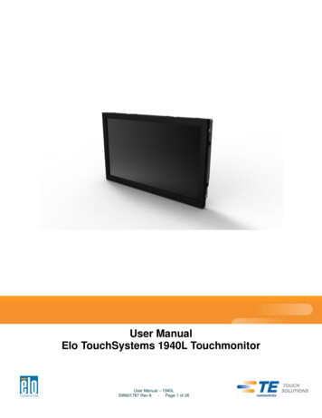
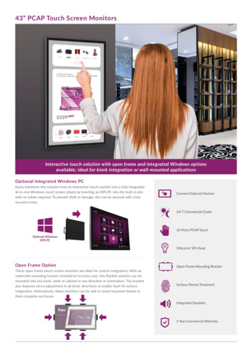
Chapter 2: InstallationUnpacking the Touch monitorOpen the carton and verify the following items are present: Touchmonitor with protective sheet for its face Elo TouchTools CD Quick Install Guide DVI cable VGA cable USB cable AC-DC power adapter AC Power Cable Audio Cable Serial CableConnector Panel & InterfacesRemove the cable cover on the back of the unit to access the Touchmonitor’s connector panel. 2013 Elo Touch Solutions, Inc. All rights reserved.User Manual 2401LMSW200127 Rev APage 13 of 32
Touchmonitor Connections1. Connect the DVI or VGA video cables between the monitor’s DVI/VGA input connectors andyour DVI/VGA video source, respectively. Tighten the video cable’s screws for bestperformance.2. Connect the USB touch cable between the monitor’s USB connector and your PC’s USB port.3. Connect the audio cable between the monitor’s Audio In jack and your audio source.4. Select the correct power cable for your region. Connect the cable between the AC powersource and the power adapter’s input connector. Connect the power adapter’s DC outputconnector to the monitor’s input power jack.5. Be sure to reinstall the cable cover and secure with appropriate screws. Cables can berouted inside the stand – remove and replace the stand cable cover for access and routing.6. The Touchmonitor ships in an OFF state. Press the power button to turn it on. 2013 Elo Touch Solutions, Inc. All rights reserved.User Manual 2401LMSW200127 Rev APage 14 of 32
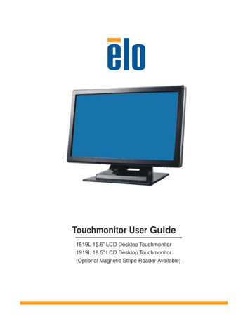
Installing the Touch Technology Software DriversSome software installation is required for your Touchmonitor to work with your computer.The drivers for the Windows 7, XP, Vista, WePOS, and 32-bit Server 2003 operating systems areprovided with your Touchmonitor on a CD.Visit the Elo Touch Solutions website www.elotouch.com for: The most up-to-date touch driver versions Additional touch driver information Detailed touch driver installation guides Touch drivers for other operating systemsDownload the appropriate driver for your application and follow the onscreen prompts.For Windows XP, Vista, Server 2003, Server 2008, and WEPOS installations, install the “USBTouchscreen Drivers” when prompted.If you do not have the internet available, insert the Elo TouchTools CD into your computer’sCD-ROM drive. The CD should automatically run the Elo TouchTools application. Select “InstallDriver for This computer”: 2013 Elo Touch Solutions, Inc. All rights reserved.User Manual 2401LMSW200127 Rev APage 15 of 32
For Windows 7 installations, check the “Install driver” box under “Elo USB Interfaces – OtherTouchscreens”After accepting the end-user license agreement, the drivers will finish installing.Reboot your computer after the install is complete. 2013 Elo Touch Solutions, Inc. All rights reserved.User Manual 2401LMSW200127 Rev APage 16 of 32
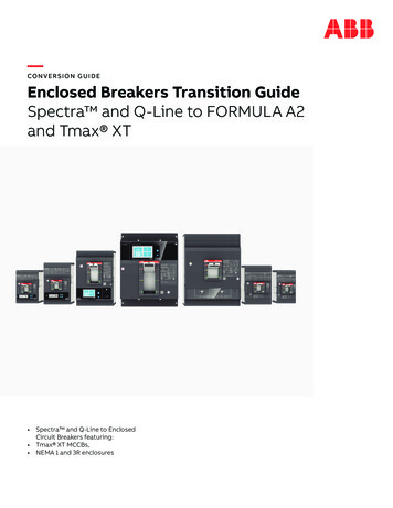
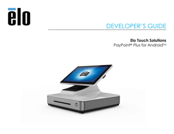
Chapter 3: MountingGeneral Mounting InformationThe OSD text can be rotated through the OSD menu to better suit your mounting orientation.The holes located on the top and bottom of the Touchmonitor case are for ventilation. Do not block,cover, or insert anything inside the ventilation slots.Rear VESA MountA four-hole 100x100mm mounting pattern for M4 screws is provided on the rear of the monitor.Remove the stand using a Phillips screwdriver to access this mounting interface. The VESAFDMI-compliant mounting is coded: VESA MIS-D, 100, C 2013 Elo Touch Solutions, Inc. All rights reserved.User Manual 2401LMSW200127 Rev APage 17 of 32
Stand MountingThreaded through-holes are provided on the bottom of the stand base for mounting or securing.VESA Mounting OptionsThe following companies provide VESA mounting devices compatible with your touch monitor -888-8458651-681-7600www.ergotron.comInnovative Office rod.comMRI800-688-2414www.mediarecovery.com 2013 Elo Touch Solutions, Inc. All rights reserved.User Manual 2401LMSW200127 Rev APage 18 of 32
Chapter 4: OperationPowerTo turn the Touchmonitor on or off, press the Touchmonitor power button once.The Power Status LED on the bottom of the Touchmonitor functions according to the following table:Touchmonitor/Computer Module statusOFFSLEEPONLED statusOFFORANGEGREENThe system consumes low power when in SLEEP and OFF modes. For detailed power consumptionspecifications, refer to technical specifications on the Elo website http://www.elotouch.comTouching the screen will bring the attached host PC out of SLEEP mode (similar to moving the mouseor pressing a keyboard key).To improve reliability and reduce wasteful power consumption, disconnect the AC power cable fromthe power adapter when long periods of disuse are planned.TouchYour IntelliTouch Touchmonitor is factory-calibrated and should not need manual calibration (unlessthe input video is not fully scaled to the native resolution, or the touch experience needs to becalibrated to a specific user).VideoA display’s native resolution is its width and height measured in number of pixels. Generally, for bestperformance, an image displayed on this monitor will look best when your computer’s output resolutionmatches this monitor’s native resolution of 1920x1080.For computer output resolutions at non-native resolutions, the monitor will scale the video to its panel’snative resolution. This involves stretching or compressing the input image as needed in the X- andY-dimensions to fit the display’s native resolution. An unavoidable byproduct of the scalingalgorithms is a loss of fidelity when the computer’s output video image is scaled by the monitor to fitthe display. This loss of fidelity is most apparent when viewing feature-rich images at close distances 2013 Elo Touch Solutions, Inc. All rights reserved.User Manual 2401LMSW200127 Rev APage 19 of 32
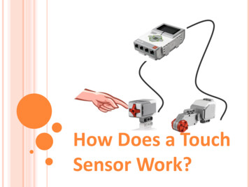
(for example images containing small-font text).Your Touchmonitor will likely not require video adjustments. However, for analog VGA video, variationsin video graphic card outputs may require user adjustments through the OSD to optimize the quality ofthe Touchmonitor’s displayed image. These adjustments are “remembered” by the Touchmonitor. Also,to reduce the need for adjustments for different video mode timings, the monitor correctly scales anddisplays some of the video industry’s most common video timing modes. Refer to the technicalspecifications for this monitor at http://www.elotouch.com for a list of these Preset Video Modes.On-Screen Display (OSD)Four OSD buttons are on the bottom of the monitor. These can be used to adjust various displayparameters.The buttons and their functionality are:ButtonMenuFunction when OSD is not displayed:Display OSD main menuDisplay OSD Contrast submenuDisplay OSD Brightness submenuSelectFunction when OSD is displayed:Return to previous OSD menuIncrease value of selected parameter /select next menu itemDecrease value of selected parameter /select previous menu itemEnter“Auto Adjust” feature(VGA mode only) Select submenu to enterUsing the OSD buttons controls an on-screen graphical user interface which displays on top ofyour input video, allowing intuitive adjustment of the following display positionRecallDefaultsAvailable AdjustmentIncrease/decrease monitor contrast.Default: best gray-shade performanceIncrease/decrease monitor brightness.Default: maximumMoves the image vertically on the display in single-pixel increments.Default: centered.Only applicable for VGA input videoMoves the image horizontally on the display in single-pixel increments.Default: centered.Only applicable for VGA input videoSelecting “Recall Defaults” restores all factory default settings for OSD-adjustableparameters (except OSD Language) and for Preset Video Mode timings. 2013 Elo Touch Solutions, Inc. All rights reserved.User Manual 2401LMSW200127 Rev APage 20 of 32
Selects the display’s color temperature. The available color temperatures are 9300K,6500K, 5500K, 7500K, and User Defined. If the User Defined option is selected, theColoruser can change the color temperature by changing individual R, G, and B gains on aTemperaturescale from 0 to 100.Default: User Defined with R, G, and B all set to 100.Adjusts the volume of the internal speakers output.VolumeAdjusts sharpness of the displayed images.SharpnessDefault: no sharpness adjustmentAllows fine adjustments of the panel’s pixel dot clock phase.PhaseOnly applicable for VGA input videoAllows fine adjustments of the panel’s pixel dot clock.ClockOnly applicable for VGA input videoMoves the OSD horizontally on the displayOSDDefault: centered.H-positionMoves the OSD vertically on the displayOSDDefault: centered.V-positionAdjusts how long a period of OSD button inactivity the Touchmonitor will wait beforeOSD Timeout closing the OSD. The adjustable range is between 45 and 255 seconds.Default: 45 secondsAutomatically adjusts the system clock to the input analog VGA video signal, affectingAuto Adjust the H-position, V-position, Clock, and Phase menu items.Only applicable for VGA input videoSelects which language the OSD information is displayed in. The availablelanguages are: English, French, German, Spanish, Swedish, Italian, SimplifiedOSDChinese, Polish, and Japanese.LanguageDefault: English.Select input video source : VGA or DVIInput VideoDefault: VGAAll Touchmonitor adjustments made through the OSD are automatically memorized as soon as theyare entered. This feature saves you from having to reset your choices every time the Touchmonitor isunplugged or powered off and on. If there is a power failure, the Touchmonitor settings will not defaultto the factory specifications. 2013 Elo Touch Solutions, Inc. All rights reserved.User Manual 2401LMSW200127 Rev APage 21 of 32
OSD and Power LockoutsPress and hold the “Menu” and “Up” buttons for two seconds to enable/disable the OSD Lockingfeature. When the OSD Locking is enabled, pressing any of the Menu, Up, Down, or Select keys willhave no effect on the system.Press and hold the “Menu” and “Down” buttons for two seconds to enable/disable the Power Lockingfeature. When the Power Locking is enabled, pressing the power switch will have no effect on thesystem.AudioWhen headphonesare plugged into the headphone output jack, the internal speakers turn off andaudio is played over the headphones.Volume for the speaker and headphone outputs can be controlled by the OSD. 2013 Elo Touch Solutions, Inc. All rights reserved.User Manual 2401LMSW200127 Rev APage 22 of 32
Chapter 5: Technical SupportIf you are experiencing trouble with your Touchmonitor, refer to the following suggestions. If theproblem persists, please contact your local dealer or contact Elo Touch Solutions Customer Service.Solutions to Common ProblemsProblemSuggested TroubleshootingCheck that the AC power cable is properlyThe Touchmonitor does not respond whenconnected.turning on the system.Verify the AC power source is functioning.Use the OSD to increase the brightness.Monitor display is dimUse the OSD to increase the contrast.If the Power Status LED is blinking, the monitor orComputer Module may be in SLEEP mode. PressMonitor display is blank.any key / move the mouse / touch the Touchscreento see if the image reappears.Adjust your computer’s resolution/timing mode to beMonitor displays an “Out Of Range”within the allowable timing ranges specified for yourmessageTouchmonitor (see website for specifications)Verify your PC has the latest Elo drivers installed.Touch functionality doesn’t workPerform the calibration routine provided with thelatest Elo drivers.Technical AssistanceVisit www.elotouch.com/products for technical specifications for this deviceVisit www.elotouch.com/go/websupport for online self-help.Visit www.elotouch.com/go/contactsupport for technical support.See this user manual’s last page for world
Storage / Transportation -20 C to 65 C Humidity (non-condensing) Operating 20% to 80% Storage / Transportation 10% to 90% Altitude Operating 0 to 3,000m 0Storage / Transportation to 12,192m 2401LM Touchmonitor for Healthcare Applications is intended for general use in hospital environment for data collection and display for reference.