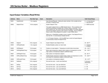
Transcription
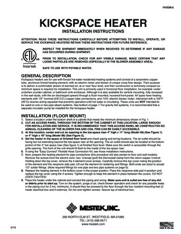
HVIOM-5KICKSPACE HEATERINSTALLATION INSTRUCTIONSATTENTION: READ THESE INSTRUCTIONS CAREFULLY BEFORE ATTEMPTING TO INSTALL, OPERATE, ORSERVICE THE KICKSPACE HEATERS! RETAIN THESE INSTRUCTIONS FOR FUTURE REFERENCE.INSPECT THE SHIPMENT IMMEDIATELY WHEN RECEIVED TO DETERMINE IF ANY DAMAGEHAS OCCURRED DURING SHIPMENT.PRIOR TO INSTALLATION, CHECK FOR ANY VISIBLE DAMAGE. MAKE CERTAIN THAT ANYLOOSE PARTICLES ARE REMOVED (ESPECIALLY IN THE BLOWER ASSEMBLY AREA).SAFE TO USE WITH POTABLE WATER.GENERAL DESCRIPTIONKickspace heaters are for use with forced hot water residential heating systems and consist of a serpentine coppertube, aluminum finned heating element, with an electric motor and blower of unique cross flow design. Their purposeis to deliver a comfortable stream of warmed air, at or near floor level, and their construction is extremely compact sominimum space is required for installation. This unit is primarily used in horizonal floor installation, for example: undera kitchen counter cabinet, or bathroom sink enclosure. Although it is also available for verticle mounting, fully recessedin the wall studs, with the air discharged upward through a flush mounted, louvered front panel. All types have heatingelements with 1/2" nominal (5/8 O.D.) copper tube connections, and 115V. electric blower motor, interwired with a 120 F(49 C) reverse acting aquastat that prevents operation until hot water is circulating. These units are NOT intended tobe used on one or two pipe steam systems. See bottom of page 7. For gravity fed systems, it is recommended that aseparate circulator pump be installed for the kickspace heater.INSTALLATION (FLOOR MOUNT)1. Select a location under the bottom shelf of a cabinet that meets the minimum dimensions shown in Fig. 1.2. CUT AN ACCESS PANEL THROUGH THE BOTTOM OF THE CABINET AT THIS LOCATION, LARGE ENOUGHFOR INSTALLATION AND SERVICE. IT IS RECOMMENDED THAT THIS ACCESS PANEL BE CONSTRUCTED SOANNUAL CLEANING OF THE BLOWER FAN AND COIL FINS CAN BE EASILY ACCESSIBLE.3. At this location, center and cut an opening in the toe-space riser 4'' high x 11'' long (Model 48) (See Figure 1)or 4'' high x 18'' long (Model 88) (See Figure 2).4. Set the heater in the space at finished floor level and check piping and wiring locations. The air outlet should befacing but not extending beyond the toe-space riser at the opening. The air outlet should also be located at the bottomportion of the 4'' toe-space riser (See figure 1) at finished floor level. Make sure the switch is accessible through thegrille opening. The front of the unit should fit flush to the inside of the toe space riser.6. If using the "Easy Connect" Flexible Hose Connection Kit, see those installation instructions.7. Next, prepare the heating element for pipe connections (this procedure will also pertain to floor and wall models).Remove the screws from the electric conn. box. Unsnap (pull) the thermostat clamp from the return copper U-bend.Holding down the top cover, remove the 4 element cover screws. Carefully remove this top cover noting the positionof the element and the neoprene side pad. Lift out the element for soldering and fittings. Both ends are sized to accept1/2'' solder fittings. (Note required fittings for one pipe and two pipe systems on page 6).8. Replace the heating element in the bottom cover in the proper position. Place the neoprene side pad in position andreplace the top cover using the 4 screws. Tighten enough to keep the element in place between the covers. DO NOTOVER-TIGHTEN!9. Place the heater under the cabinet and connect the piping and wiring. Make sure unit & outlet are free of any dirtor debris prior to start up. Turn on the system, purge of air, check blower operation and check for any possible leaksin the piping (run for 2 hrs. minimum). It should then be screwed to the floor through the four resilient mounting feet (2inside electrical box and 2 external). Do not over-tighten screws. Secure top of electrical box.6/18260 NORTH ELM ST., WESTFIELD, MA 01085TEL: (413) 568-9571www.mestek.com1.
MODEL 48Figure 1ELECTRICCONNECTIONBOX12 1/4(311)12 3/4(324)AQUASTAT4" FRONTGRILLE(102)6 1/4 MIN.(159)RETURNAIRSUPPLY6" PIPECENTERS(152)SWITCHRETURNHEATEDDISCHARGEAIR2" 303-AMODEL 88Figure 219 1/4(489)12 3/4(324)AQUASTAT4" FRONTGRILLE(102)6 1/4 MIN.(159)RETURNAIRSUPPLY6" PIPECENTERS(152)SWITCHRETURNHEATEDDISCHARGEAIR14 1/2(368)Dimensions shownin English and metric ( ).MODEL 48KICKSPACE HEATER(BTUH Ratings Based On 65 F Entering 84482551665507CAT-68 304-AMODEL 88KICKSPACE HEATER(BTUH Ratings Based On 65 F Entering 00787588509825 10,800 11,775160 F 170 F 180 F 190 F 200 F 210 FLOW SPEED AIR FLOW: 30 CFMHIGH SPEED AIR FLOW: 53 CFMVOLTAGE: 110-120V AC; 1 PH 60 HZFRICTION LOSS: 0.11 FT @ 1 GPHWATER CONNECTIONS: 1/2" NOMINAL COPPER PIPETHERMOSTATIC FAN SWITCH: BI-METAL TYPE;CONTACTS CLOSE @ 120 F /-5 F; 15 F DIFFERENTIAL2.2" AIRDISCHARGE(51)160 F 170 F 180 F 190 F 200 F 210 F6180LOW SPEED AIR FLOW: 60 CFMHIGH SPEED AIR FLOW: 103 CFMVOLTAGE: 110-120V AC; 1 PH 60 HZFRICTION LOSS: 0.18 FT @ 1 GPHWATER CONNECTIONS: 1/2" NOMINAL COPPER PIPETHERMOSTATIC FAN SWITCH: BI-METAL TYPE;CONTACTS CLOSE @ 120 F /-5 F; 15 F DIFFERENTIAL6575
INSTALLATION OF KICKSPACE WALL MODELSFigures 3 and 5 show exploded views of the wall models. Figure 4 shows the “IW” type mounted in a wall with an airoutlet at the top of the unit. Figure 6 shows the wall mounted “EW”. The louvers of the front panel will direct the air flow asshown. Use the following procedures for installation:VERTICAL IN WALL INSTALLATION35SWITCHAIR FLOW1IWELECTRICALRETURNSUPPLYFigure 3VERTICALFIGURE 3PARTS LIST1IW.2IW.3.4IW.5.Figure 4FRONT PANEL ASS'YBACK RECESSED PANEL ASS'YFAN/COIL UNIT (FCU)FRONT PANEL MTG. SCREWSLOCKWASHERS6. FLANGED NUTS7. FAN/COIL UNIT ELECTRICAL CONTROLBOX COVER8. WASHERS (PLASTIC)9. SNAP-CAP (PLASTIC)PART #3 AND #7 (FAN/COIL UNIT) WILL BE SHIPPED IN IT'S OWN CARTON. ALL REMAINING PARTSARE INCLUDED IN A SEPERATE CARTON.TYPE “IW”:1.2.3.4.Frame an opening between wall studding as shownin Figure 4. Model 48 will fit between studs that areon 16'' centers. Model 88 will require a small amountof framing to suit the mounting. A 7/8'' diameter holeis provided at the bottom of the cabinet interior toprovide entrances for electrical connections, and a7/8'' diameter knockout is provided at the rear of themotor in the electrical control box. A 2-1/2'' diameterhole is provided at the bottom of the cabinet interiorto provide an entrance for piping connections. Cuthorizonal framing to clear, as necessary.After removing the front panel mounting screws (Item4IW), remove the front louvered panel (Item 1IW).Notice the direction of the louvers (see the air flowdirection label on inside front label).Nail the recessed cabinet (Item 2IW) to the framedopening at both sides.Mount the Fan/Coil Unit (Item 3) to the recessed backpanel, remove the electrical control box cover fromfan/coil unit. Secure the fan/coil unit in place usingItems 5 & 6 as shown in Figure 3. Do not over tighten.5.Remove the heating element from the fan/coil unit(Item 3) following the procedure described in theinstallation of horizontal, step 6. Hold this element andfittings temporarily in place in the recessed cabinetbefore soldering to check for clearance and length oftubing required.6. After piping connections have been made, returnthe element to the cabinet as described in horizontalinstallation, step 8.7. Electrical connections for the wall units are to bemade as shown on page 5.8. Make final piping and electrical connections (seepages 5 & 6) to the system in the cabinet. Securein place the electrical control box cover. Turn on thesystem, purge of air, check blower operation, andcheck for any possible leaks in the piping.9. Replace front panel (Item 1IW), place washers (Items8) in required positions, screw through holes andtighten.10. Place snap-cap (Item 9) over washer at angle. Pushsnap-cap (Item 9) DOWN firmly until it engages witha snap.3.
VERTICAL EXTERNAL WALL INSTALLATIONACCESS DOOR35SWITCH1EWELECTRICALCONNECTIONBOXAIR FLOWRETURNFINISHED FLOORSUPPLYFigure 5TYPE “EW”FIGURE 5PARTS LIST1EW.2EW.3.4EW.5.6.7.8.9.Figure 6FRONT PANELBACK PANELFAN/COIL UNIT (FCU)FRONT PANEL MTG. SCREWSLOCKWASHERSFLANGED NUTSELECTRICAL CONTROL BOX COVERWASHERS (PLASTIC)SNAP-CAP (PLASTIC)PART #3 (FAN/COIL UNIT) WILL BE SHIPPED IN IT'S OWN CARTON. ALL REMAINING PARTS AREINCLUDED IN A SEPERATE CARTON.TYPE "EW":1.2.3.4.4.Locate the heater at or near floor level, and plan forwater and electrical services feed through the bottomof the enclosure. If over rough flooring, be sure to allowclearance above the finish that will not interfere withremoval of the front panel. The back panel (Item 2EW)should be screwed or nailed securely to the wall.Remove the front panel (Item 1EW) by removing thetwo screws at the bottom. Then pull the bottom awayfrom the enclosure and lift the top from its hookedposition. To replace the panel, press down firmly toengage it in the top channel and lock the two sidesover the front edge of the enclosure at the clamps.Mount the Fan/Coil Unit (Item 3) to the back recessedpanel, remove the electrical control box cover fromfan/coil unit. Secure the fan/coil unit in place using items 5 & 6 as shown in Figure 5. Do not overtighten.Soldering may be done to the fan/coil unit (Item 3)with care within vertical enclosure, or the elementmay easily be removed, if so desired. Follow thesame procedure as described in HorizontalInstallation, step 6.5.6.7.8.9.After the piping connections are made, return theelement to the cabinet as described in horizontalInstallation, step 7. Removal and replacement willbe simpler if done in a horizontal position before theenclosure is secured to the wall.Electrical connections for the wall units are to bemade as indicated on page 5.Make final piping and electrical connections (seepages 5 & 6 ) to the system in the cabinet. Turn onthe system, purge of air, check blower operation, andcheck for any possible leaks in the piping.Replace front panel (Item 1EW), place washers (Item8) in required positions, screw through holes andtighten.Place snap-cap (Item 9) over washer at angle. Pushsnap-cap (Item 9) down firmly until it engages with asnap.
ELECTRICAL CONNECTIONSCAUTION! For Supply Connections, use wires suitable for at least 194 F (90 C).All electrical connections must conform to local and national codes.A shaded pole motor is used to drive the Hideavector3 blower on 115 -120 V. 60 hz. Since current drain is verysmall, wiring codes for short circuit protection only will apply. The motor is connected in series with a normallyopen aquastat in contact with the heating element. Therefore, the blower runs only when unit is sufficiently hot andthe switch is in the "min" or "max" position (not "off"). A ground screw is supplied with all units.Electrical connections are to be made to all units following the diagrams below. Choose the diagram that best suitsyour application.Since the blower runs on all models only when the system circulator pumps hot water through the unit, simplyconnect it to the 115 V line. The blower then starts after a short warm-up, and stops a few minutes after thecirculator shuts off (see Diagram 1).Adding a line voltage type room thermostat will permit the setting of a maximum room temperature (see Diagram2). This 'T' stat will only operate the fan/coil unit. If the circuit or system circulator is not running, the fan/coil unit willnot operate.L2115V LINE(NEUTRAL)WHTSPDTL1 (HOT)2LINE IN1BLUERT-STATL1 (HOT)W2LINE INLINE VOLTROOM T'STATBLKMIN(NEUTRAL)WHTSPDT115V LINEREDMAXOFF3115/1/60(GND)L2BLOWERMOTORGREEN BLUET-STATBLUEGREEN SCREWCAT-68252-ACAT-68253-ADiagram 2Diagram 1WIRING DIAGRAM 1WIRING DIAGRAM 2Connection through a circulator or zone auxiliary switch may also be used to permit instant shutdown of theblower as the circulator stops (see Diagram 3).115V LINELOW VOLTROOM T'STATZONE VALVEW/AUX. SW.CIRCULATORL2(NEUTRAL)WHTSPDT2TRANS115/24V11L1 E IN115/1/60Diagram 3CAT-68254-AWIRING DIAGRAM 3MOTOR 200.03411530.73200.0341155.
SYSTEM CONSIDERATIONSKickspace heaters should be connected only to circulating hot water systems where at least 1 gpm water flow isexpected. They are essentially small unit heaters, and will work on one or two pipe systems, or in a series loop wherepressure and temperature drop can be tolerated (see capacity charts and piping diagrams). These units are not designedfor use with steam systems. See bottom paragraph on page 7. These units are not recommended to be used with agravity flow system.PIPING CHARTSONE PIPE SYSTEMUP FEEDTWO PIPE SYSTEMAIR VENTAIR VENTSUPPLYHOT WATERMAINSUPPLYWATERFLOWDIRECTIONAL FLOW "T"OR MONOFLOW "T"STANDARD "T"12" MIN.18" MAX.HOT WATERMAINWATERFLOWSTANDARD "T"DIRECTIONAL FLOW "T"OR MONOFLOW "T"WATERFLOWCAT-68214NOTE: In an up feed system, unit is located above hot water supply line. In a down feedsystem, unit is located below hot water supply line.For one pipe system down feed, two directional flow tees should be used. They should be spaced 12 to 18inches apart. The directional arrow on the directional flow 'T' at the return side should point towards the supplydirectional flow 'T'.If directional flow (mono-flo) tee's are not available, an adjustable screw operated flow control or circuit settercan be placed between the two standard tee's in a one pipe system.For consistent response of the reverse acting thermostat, and effective outlet air temperature, the average watertemperature should not be below 120 F (49 C). Blower motor shuts off at 105 F (41 C) and will not operate untilwater temperature reaches 120 F (49 C).If utilizing water temperature below 120 F (49 C), the blower will not operate with the self contained aquastat. An optionallow temperature aquastat, 110 to 95 F (43 to 35 C) is available.MAINTENANCE & SERVICEProperly installed, the Kickspace heater should require very little attention. Since the heating element is carefullyconstructed and tested, and of non-ferrous materials, it should never require service. The cross-flow blower has beenthoroughly engineered, with ball bearings for 10,000 hrs. bearing life expectancy. As with any electrical rotating device,a yearly inspection and cleaning is recommended. Wherever there is air movement, there will be some accumulationof dust and lint. In this case it will collect on the rotor blades and air passage of the unit. Regular cleaning with a vacuumcleaner tool is advised, with frequency determined by prevailing conditions. Always make sure that the air grille is notblocked by foreign objects or materials.6.
REPLACEMENT PARTS LISTDescriptionMotor-Fan AssemblyStandard Aquastat Assembly (120 – 105 F)Low Temp. Aquastat Assembly (110 – 95 F)Heating Element2 Speed Fan SwitchOutlet Grille w/ screwsLouvered Front Panel (Model IW only)Louvered Front Panel (Model EW only)Part 65-002Model4888xxxxxxxxxxxxxxxxPart ionQuick-Connect Hose KitSpeed Control SwitchSTEAM CONDENSATE DIAGRAMSTEAM CONDENSATEDIAGRAMOn a typical forced hot water system, connect return to inlet side of circulator and supply upstream of remotely operatedvalve. Unit may also be connected to mains of an existing loop system of sufficient capacity. Operation will be influencedby the system circulator and associated controls.Installation of a pump and line voltage thermostat will provide the unit with its own “zone” control.With the addition of a circulator pump, hot water storage tanks may be used (where codes permit) as a supply sourceif proper precautions are taken, and if realitively low water temperatures can be tolerated. Be sure tank can supplyadditional load of the Kickspace heater and 120 F water. Supply is taken from top of tank, and returns at the cold waterinlet with a check valve. Do not return to bottom drain tapping.Operation from steam boiler water is entirely possible as long as supply and return connection is installed below level ofwater line on a steam boiler. This installation requires an optional circulator pump and line voltage thermostat. Check localbuilding codes.7.
5 YEAR LIMITED WARRANTYMODELS 48 AND 88The “Manufacturer” warrants to the original owner at the original installation site that the Models 48 and 88 heaters (the“Product”) will be free from defects in material or workmanship for five (5) years from the date of shipment from the factory. Ifupon examination by the Manufacturer the Product is shown to have a defect in material or workmanship during the warrantyperiod, the Manufacturer will repair or replace, at its option, that part of the Product which is shown to be defective.This limited warranty does not apply:(a) if the Product has been subjected to misuse or neglect, has been accidentally or intentionally damaged, has notbeen installed, maintained or operated in accordance with the furnished written instructions, or has been altered ormodified in any way.(b) to any expenses, including labor or material, incurred during removal or reinstallation of the defective Product orparts thereof.(c) to any workmanship of any installer of the Product.This limited warranty is conditional upon:(a) shipment, to the Manufacturer, of that part of the Product thought to be defective. Goods can only be returned withprior written approval from the Manufacturer. All returns must be freight prepaid.(b) determination, in the reasonable opinion of the Manufacturer, that there exists a defect in material or workmanship.Repair or replacement of any part under this Limited Warranty shall not extend the duration of the warranty with respect tosuch repaired or replaced part beyond the stated warranty period.THIS LIMITED WARRANTY IS IN LIEU OF ALL OTHER WARRANTIES, EITHER EXPRESS OR IMPLIED, AND ALLSUCH OTHER WARRANTIES, INCLUDING WITHOUT LIMITATION IMPLIED WARRANTIES OF MERCHANTABILITYOR FITNESS FOR A PARTICULAR PURPOSE, ARE HEREBY DISCLAIMED AND EXCLUDED FROM THIS LIMITEDWARRANTY. IN NO EVENT SHALL THE MANUFACTURER BE LIABLE IN ANY WAY FOR ANY CONSEQUENTIAL,SPECIAL, OR INCIDENTAL DAMAGES OF ANY NATURE WHATSOEVER, OR FOR ANY AMOUNTS IN EXCESS OFTHE SELLING PRICE OF THE PRODUCT OR ANY PARTS THEREOF FOUND TO BE DEFECTIVE. THIS LIMITEDWARRANTY GIVES THE ORIGINAL OWNER OF THE PRODUCT SPECIFIC LEGAL RIGHTS. YOU MAY ALSO HAVEOTHER RIGHTS WHICH MAY VARY BY EACH JURISDICTION.260 NORTH ELM ST., WESTFIELD, MA 01085TEL: (413) 568-9571www.mestek.com
INSTALLATION INSTRUCTIONS HVIOM-5 KICKSPACE HEATER 260 NORTH ELM ST., WESTFIELD, MA 01085 TEL: (413) 568-9571 www.mestek.com . If using the "Easy Connect" Flexible Hose Connection Kit, see those installation instructions. 7. Next, prepare the heating element for pipe connections (this procedure will also pertain to floor and wall models). .