Transcription
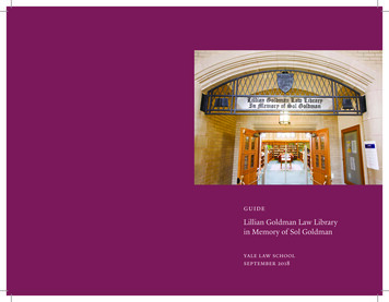
Inside US: 1 (877) 432-9908Bulletin No. GEXRACK-DOutside US: 1 (717) 767-6511Drawing No. LP0970www.redlion.netReleased 2018-02-20Graphite Expansion Racks EASY TO ADD I/O CAPABILITY WITH GRAPHITE PLUG-INMODULES CONFIGURED USING CRIMSON 3 SOFTWARECALUMINUM CASE CONSTRUCTION FOR BOTH THE EXPANSIONRACK AND THE I/O MODULESULUS LISTEDRIND. CONT. EQ.E302106CULRUSLISTEDFOR USE IN HAZARDOUS LOCATIONS:Class I, Division 2, Groups A, B, C, and DT4IND.CONT. EQ.E317425II 3 G Ex nA IIC T4 Gc-40 C TAMB 75 CDEMKO 14 ATEX 1387XIECEx UL 15.0035XGENERAL DESCRIPTIONWARNINGCAUTION: -RiskEXPLOSIONof Danger.HAZARD - DO NOT DEQUIPMENTRead completeUNLESSinstructionsPOWERprior HASto installationBEEN SWORand AREAoperationIS KNOWNof the unit.TO BE NON-HAZARDOUEach expansion rack can support up to 3 Graphite modules, and up to4 racks can be bolted together, to provide up to 12 Graphite modules perexpansion rack system. The expansion racks connect and communicatevia proprietary USB connection to the various Graphite host devices, viastandard USB A/B cable. The GEXRACK1 USB base rack provides theinterface to the Graphite host, and up to 3 GEXRACK2 3-Port expansionracks can be attached to the USB base rack. The backplane connectionbetween expansion racks provides power and communications for thedownstream racks and modules. The GEXRACK1 also offers a filteredpower supply for both the rack and the Graphite host device which canbe used when installing in electrically noisy environments.The Graphite host devices, equipped with serial ports as well asEthernet port(s), allows the system to share data with PCs, PLCs, andSCADA systems.The expansion racks snap easily onto standard top hat (T) profile DINrail, or can be bolted directly to the panel in high vibration environments.WARNING - EXPLOSION HAZARD - DO NOT DISCONNECTEQUIPMENT UNLESS POWER HAS BEEN SWITCHED OFFOR AREA IS KNOWN TO BE NON-HAZARDOUS.WARNING - EXPLOSION HAZARD - SUBSTITUTION OFCOMPONENTS MAY IMPAIR SUITABILITY FOR CLASS I,DIVISION 2.CONTENTS OF PACKAGEGEXRACK1:SAFETY SUMMARYAll safety related regulations, local codes and instructions that appearin the manual or on equipment must be observed to ensure personalsafety and to prevent damage to either the instrument or equipmentconnected to it. If equipment is used in a manner not specified by themanufacturer, the protection provided by the equipment may be impaired.Do not use this unit to directly command motors, valves, or otheractuators not equipped with safeguards. To do so can be potentiallyharmful to persons or equipment in the event of a fault to the unit.GEXRACK2:- Base- Base- (2) 3-position terminal blocks(Power supply filter)- (3) module port covers- (3) module port covers- Downstream port cover- Downstream port cover- User Bulletin- User BulletinDIMENSIONS In inches (mm)9.79 (248.56) *4.4 (111.91)5.83 (147.96)2.97 (76)GEXRACK1GEXRACK25.97(151.69)Module soldseparately* 3.96" for each additional base-1-
Bulletin No. GEXRACK-DReleased 2018-02-20Drawing No. LP0970SPECIFICATIONS3. CERTIFICATIONS AND COMPLIANCES:CE ApprovedEN 61326-1 Immunity to Industrial LocationsIEC/EN 61010-1RoHS CompliantATEX ApprovedII 3 G Ex nA IIC T4 GcDEMKO 14 ATEX 1387XEN 60079-0, -15IECEx ApprovedEx nA IIC T4 GcIECEx UL 15.0035XIEC 60079-0, -15UL Listed: File #E302106UL Hazardous: File #E317425IP20 Enclosure ratingABS Type Approval for Shipboard Applications4. MOUNTING REQUIREMENTS: Panel mount, or standard top hat (T)profile DIN rail mount. Panel mount hardware is not provided. The unitscan accept #5 to #10 (M3 to M4). 1.5” (38 mm) minimum length,depending on panel thickness. Washers and lock-washer recommended.Torque screws 96 to 128 ozf-in (0.68 to 0.90 Nm).5. CONNECTIONS: High compression cage-clamp terminal blockWire Strip Length: 0.3" (7.5 mm)Wire Gauge Capacity: One 14 AWG (1.63 mm) solid,two 18 AWG (1.02 mm) or four 20 AWG (0.81 mm)6. CONSTRUCTION: Case body is all metal construction.7. WEIGHT:GEXRACK1, USB 3-Port Base Rack: 1.78 lb. (795.2 g)GEXRACK2, 3-Port Expansion Rack: 1.33 lb. (596.4 g)1. POWER: 10 to 30 VDCMust use a Class 2 circuit according to National Electrical Code (NEC),NFPA-70 or Canadian Electrical Code (CEC), Part I, C22.1 or aLimited Power Supply (LPS) according to IEC/EN 60950-1 orLimited-energy circuit according to IEC/EN 61010-1.Power connection via removable three position terminal block.Available Power For Modules: 13 W per 3-port rack; 52 W total forexpansion rack system (up to 12 modules).Available Power For Host: 60 W.2. ENVIRONMENTAL CONDITIONS:Operating Temperature Range: -40 to 75 C, or lowest range amongequipment used in your Graphite system. Consult the user manual orwww.redlion.net/OpTemp for further details.Storage Temperature Range: -40 to 85 CPanel Mount Vibration to IEC 68-2-6: Operational 5-500 Hz, 4 gPanel Mount Shock to IEC 68-2-27: Operational 40 g (10 g, modules w/relays)* DIN Rail Mount Vibration to IEC 68-2-6: Operational 5-500 Hz, 2 g* DIN Rail Mount Shock to IEC 68-2-27: Operational 15 g (10 g,modules w/relays)* DIN latch CAM must be in latched position.Requires DIN Rail type: DIN 1010, DIN 1065, or DIN 3065.Operating and Storage Humidity: 80% max. relative humidity, noncondensingAltitude: Up to 2000 metersInstallation Category II, Pollution Degree 2 as defined in IEC/EN 60664-1.EMC INSTALLATION GUIDELINESAlthough Red Lion Controls products are designed with a high degreeof immunity to Electromagnetic Interference (EMI), proper installation andwiring methods must be followed to ensure compatibility in eachapplication. The type of the electrical noise, source or coupling methodinto a unit may be different for various installations. Cable length, routing,and shield termination are very important and can mean the differencebetween a successful or troublesome installation. Listed are some EMIguidelines for a successful installation in an industrial environment.1. A unit should be mounted in a metal enclosure, which is properlyconnected to protective earth.2. Use shielded cables for all Signal and Control inputs. The shieldconnection should be made as short as possible. The connection pointfor the shield depends somewhat upon the application. Listed beloware the recommended methods of connecting the shield, in order oftheir effectiveness.a. Connect the shield to earth ground (protective earth) at one endwhere the unit is mounted.b. Connect the shield to earth ground at both ends of the cable, usuallywhen the noise source frequency is over 1 MHz.3. Never run Signal or Control cables in the same conduit or raceway withAC power lines, conductors, feeding motors, solenoids, SCR controls,and heaters, etc. The cables should be run through metal conduit thatis properly grounded. This is especially useful in applications wherecable runs are long and portable two-way radios are used in closeproximity or if the installation is near a commercial radio transmitter.Also, Signal or Control cables within an enclosure should be routed asfar away as possible from contactors, control relays, transformers, andother noisy components.4. Long cable runs are more susceptible to EMI pickup than short cable runs.5. In extremely high EMI environments, the use of external EMIsuppression devices such as Ferrite Suppression Cores for signal andcontrol cables is effective. The following EMI suppression devices (orequivalent) are recommended:Fair-Rite part number 0443167251 (Red Lion Controls #FCOR0000)Line Filters for input power cables:Schaffner # FN2010-1/07 (Red Lion Controls #LFIL0000)6. To protect relay contacts that control inductive loads and to minimizeradiated and conducted noise (EMI), some type of contact protectionnetwork is normally installed across the load, the contacts or both. Themost effective location is across the load.a. Using a snubber, which is a resistor-capacitor (RC) network or metaloxide varistor (MOV) across an AC inductive load is very effective atreducing EMI and increasing relay contact life.b. If a DC inductive load (such as a DC relay coil) is controlled by atransistor switch, care must be taken not to exceed the breakdownvoltage of the transistor when the load is switched. One of the mosteffective ways is to place a diode across the inductive load. MostRed Lion products with solid state outputs have internal zener diodeprotection. However external diode protection at the load is always agood design practice to limit EMI. Although the use of a snubber orvaristor could be used.Red Lion part numbers: Snubber: SNUB0000Varistor: ILS11500 or ILS230007. Care should be taken when connecting input and output devices to theinstrument. When a separate input and output common is provided,they should not be mixed. Therefore a sensor common should NOT beconnected to an output common. This would cause EMI on thesensitive input common, which could affect the instrument’s operation.Visit www.redlion.net/emi for more information on EMI guidelines,Safety and CE issues as they relate to Red Lion products.-2-
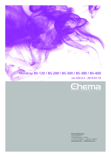
Released 2018-02-20Bulletin No. GEXRACK-DDrawing No. LP0970Block Diagram for Expansion STPORTLINEFILTERPOWERSUPPLYGEXRACK1, USB BASE RACKGEXRACK2, 3-PORT EXPANSION RACKUp to 2 AdditionalGEXRACK2 rackscan be added.(OPTIONAL)- VDCPOWERSUPPLYINPUT- HOSTPOWEROUTLETRefer to Connecting to Earth Ground, Power SupplyRequirements, and EMC Installation Guidelines sectionsof this document for more details.EXPANSION RACK INSTALLATIONPANEL MOUNTING INSTRUCTIONSDIN RAIL MOUNT AND CAM OPERATIONThe expansion rack can be mounted on a DIN rail for normalenvironments, or bolted to a panel for high vibration environments. Referto the diagram for the panel mount hole spacing.2.13(54)1.84(46.6)It is recommended that the expansion rack be DIN rail mounted only inlow vibration environments. Refer to the Specifications section for details.1. Using a screwdriver, push in and fully rotate the Cam counterclockwise to push the DIN Clip downward against spring pressurelocking it open2. Place the base on the DIN rail. Place each additional base, and slidethem together until the connectors engage. Then fasten the basestogether with the two captive screws, located at each junction.3. Using a screwdriver, push in and rotate the Cam 90 degrees clockwiseto release the DIN clip to engage the DIN rail4. Rotate the Cam an additional 90 degrees clockwise to lock the DIN clipin the closed position. The CAM must be in fully locked position tomeet the vibration specification listed.2.13(54)5.12(130)Captive Screws to fastenthe bases togetherFor hazardous location installation the following shall be taken intoconsideration:- When used in a Zone 2 environment, the device shall be panelmounted in at least Zone 2 IECEx/ATEX-Certified tool accessibleenclosure with a minimum ingress protection rating of at least IP54as defined in IEC/EN 60529.- Must be wired using Division 2 wiring methods as specified in article501-4(b), 502-4(b), and 503-3(b) of the National Electric Code,NFPA 70 for installation within the United States, or as specified insection 19-152 of Canadian Electrical Code for installation inCanada.LOCKUNLOCK-3-
Bulletin No. GEXRACK-DReleased 2018-02-20Drawing No. LP0970MODULE INSTALLATIONCONNECTING TO EARTH GROUNDThe physical order of all installed modules must match the modulesorder in Crimson. Torque screws to 6.0 pound-force inch [96 ounce-forceinch] (0.68 Nm).The third pin of the power connector is chassis ground for the unit.Your unit should be connected to earth ground.The chassis ground is not connected to signal common of the unit.Maintaining isolation between earth ground and signal common is notrequired to operate your unit. But, other equipment connected to this unitmay require isolation between signal common and earth ground. Tomaintain isolation between signal common and earth ground, care mustbe taken when connections are made to the unit. For example, a powersupply with isolation between its signal common and earth ground mustbe used. Also, plugging in a USB cable may connect signal common andearth ground.11 USB’s shield may be connected to earth ground at the host. USB’sshield in turn may also be connected to signal common.WARNING: Disconnect all powerto the unit before installing orremoving modules.POWER SUPPLY REQUIREMENTSThe Graphite expansion rack requires a 10-30 VDC power supply.Your unit may draw considerably less than the maximum rated powerdepending upon the modules being used.To ensure you do not exceed the capacity of your Graphite expansionrack power supply, calculate the total power consumption required for allof your planned modules. Each module’s maximum power consumptionis listed in the Specifications of their respective Product Bulletin. The totalpower available for modules is listed in the Graphite Expansion RackSpecifications.It is very important that the power supply is mounted correctly if the unitis to operate reliably. Please take care to observe the following points:– Voltage range stated is at the power connector, not at the powersource.– Peak efficiency occurs at the low side of the voltage range(approximately 12 V), recommended for high temperature applications.– The GEXRACK1 contains two built-in power supply line filters: onefor the expansion rack system, and one for the Graphite host. Thepower supply is wired to the POWER INPUT CONNECTOR of theGEXRACK1, then the HOST POWER OUTPUT of the GEXRACK1is wired to the Graphite host power input. This setup provides thebest EMC performance.– The power supply must be mounted close to the unit expansion rack,with usually not more than 6 feet (1.8 m) of cable between thesupply and the expansion rack. Ideally, the shortest length possibleshould be used.– Separate power supplies can be used for the Graphite host and theexpansion rack system, but EMC performance will be reduced. Boththe Graphite host and the expansion rack system must be properlyconnected to protective earth, as per the “CONNECTING TOEARTH GROUND” section.– The wire used to connect the Graphite host’s power supply shouldbe at least 22-gage wire, suitably rated for the temperatures of theenvironment to which it is being installed. If a longer cable run isused, a heavier gage wire should be used. The routing of the cableshould be kept away from large contactors, inverters, and otherdevices which may generate significant electrical noise.– A power supply with an NEC Class 2 or Limited Power Source (LPS)and SELV rating is to be used. This type of power supply providesisolation to accessible circuits from hazardous voltage levelsgenerated by a mains power supply due to single faults. SELV is anacronym for “safety extra- low voltage.” Safety extra-low voltagecircuits shall exhibit voltages safe to touch both under normaloperating conditions and after a single fault, such as a breakdown ofa layer of basic insulation or after the failure of a single componenthas occurred. A suitable disconnect device shall be provided by theend user.REMOVE RUBBERMODULE PLUG-4-
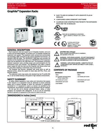
Released 2018-02-20Bulletin No. GEXRACK-DDrawing No. LP0970WIRINGWIRING CONNECTIONSSTATUS LEDAll conductors should meet voltage and current ratings for eachterminal. Also, cabling should conform to appropriate standards of goodinstallation, local codes and regulations and be suitably rated for thetemperatures of the environment to which it is being installed. When wiringthe module, use the numbers on the label to identify the position numberwith the proper function. Strip the wire, leaving approximately 1/4" (6 mm)of bare wire exposed. Insert the wire into the terminal, and tighten.USBTYPE BPOWER INPUTCONNECTORFROMPOWER SUPPLY3 CHASSIS2 DC VOLTAGE1 COMMON3 CHASSIS2 DC VOLTAGE1 COMMONWARNING - EXPLOSION HAZARD - DO NOT CONNECT ORDISCONNECT CABLES WHILE POWER IS APPLIED UNLESSAREA IS KNOWN TO BE NON-HAZARDOUS.HOST POWER OUTPUTCONNECTORTOGRAPHITE HOST(See POWER SUPPLY REQUIREMENTS for details.)CONFIGURATIONEXPANSION RACK STATUS LEDsThe Expansion Rack is configured with Windows compatibleCrimson software. The software is an easy to use, graphical interfacewhich provides a means of configuration and commissioning of newsystems. Please see the Crimson manual for more details. Crimsonsoftware is available as a no charge download from Red Lion’s website.The latest version of the software is always available from the website,and updating your copy is free.The expansion rack status LED is a bi-color LED that providesinformation regarding the USB connection.COLORCOMMUNICATING WITH THE GRAPHITEHOSTIf for any reason you have trouble operating, connecting, or simplyhave questions concerning your new Graphite unit, contact Red Lion’stechnical support.Email: support@redlion.netWebsite: www.redlion.netInside US: 1 (877) 432-9908Outside US: 1 (717) 767-6511STATUSNot operationalErrorGREENNormal operationUSB connection established andperforming normallyTROUBLESHOOTING YOUR GRAPHITEUSB HOST LEDsREDGREENEach module contains a status LED, refer to the respective Graphitemodule data sheets for details.LEDsCOLORNo USB connection with hostMODULE STATUS LEDSCommunication between the Graphite Host device and the WideExpansion Rack is accomplished over USB communication. A standardUSB 2.0 A/B cable can be used to connect the USB Host Port of the host,to the USB Device Port of the wide expansion rack. It is recommended tokeep wiring distances as short as possible. One meter or less ispreferable. Red Lion offers metal-armored, crush-proof cables for cabinetinstallations in several lengths. See Ordering information for availablepart numbers.OFFSTATUSORANGE-5-
Bulletin No. GEXRACK-DReleased 2018-02-20Drawing No. LP0970ORDERING INFORMATIONTYPEExpansion BaseAccessoriesDESCRIPTIONPART NUMBERGraphite USB 3-Port Base RackGEXRACK1Graphite 3-Port Expansion RackGEXRACK2USB Metal Armored, 0.5 Meter CableCBLUSBM0USB Metal Armored, 1 Meter CableCBLUSBM1USB Metal Armored, 2 Meter CableCBLUSBM2A listing of the entire Graphite family of products and accessories can be found at www.redlion.net.-6-
Released 2018-02-20Bulletin No. GEXRACK-DDrawing No. LP0970This page intentionally left blank-7-
Bulletin No. GEXRACK-DReleased 2018-02-20Drawing No. LP0970LIMITED WARRANTY(a) Red Lion Controls Inc. (the “Company”) warrants that all Products shall be free from defects in material andworkmanship under normal use for the period of time provided in “Statement of Warranty Periods” (available atwww.redlion.net) current at the time of shipment of the Products (the “Warranty Period”). EXCEPT FOR THE ABOVESTATED WARRANTY, COMPANY MAKES NO WARRANTY WHATSOEVER WITH RESPECT TO THEPRODUCTS, INCLUDING ANY (A) WARRANTY OF MERCHANTABILITY; (B) WARRANTY OF FITNESS FOR APARTICULAR PURPOSE; OR (C) WARRANTY AGAINST INFRINGEMENT OF INTELLECTUAL PROPERTYRIGHTS OF A THIRD PARTY; WHETHER EXPRESS OR IMPLIED BY LAW, COURSE OF DEALING, COURSE OFPERFORMANCE, USAGE OF TRADE OR OTHERWISE. Customer shall be responsible for determining that aProduct is suitable for Customer’s use and that such use complies with any applicable local, state or federal law.(b) The Company shall not be liable for a breach of the warranty set forth in paragraph (a) if (i) the defect is a resultof Customer’s failure to store, install, commission or maintain the Product according to specifications; (ii) Customeralters or repairs such Product without the prior written consent of Company.(c) Subject to paragraph (b), with respect to any such Product during the Warranty Period, Company shall, in itssole discretion, either (i) repair or replace the Product; or (ii) credit or refund the price of Product provided that, ifCompany so requests, Customer shall, at Company’s expense, return such Product to Company.(d) THE REMEDIES SET FORTH IN PARAGRAPH (c) SHALL BE THE CUSTOMER’S SOLE AND EXCLUSIVEREMEDY AND COMPANY’S ENTIRE LIABILITY FOR ANY BREACH OF THE LIMITED WARRANTY SET FORTHIN PARAGRAPH (a).-8-
A listing of the entire Graphite family of products and accessories can be found at www.redlion.net. TYPE DESCRIPTION PART NUMBER Expansion Base Graphite USB 3-Port Base Rack GEXRACK1 Graphite 3-Port Expansion Rack GEXRACK2 Accessories USB Metal Armored, 0.5 Meter Cable CBLUSBM0