Transcription
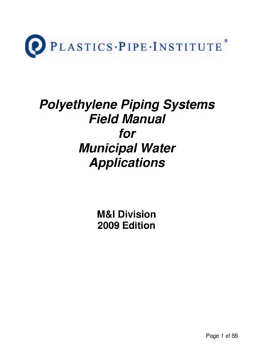
Polyethylene Piping SystemsField ManualforMunicipal WaterApplicationsM&I Division2009 EditionPage 1 of 88
Table of ContentsTable of Contents .2PE Piping Systems Overview .3Sizes, Specifications, Pressure Ratings . 4Marking . 5SAFETY! .6Flushing and Disinfecting . 6Contaminated Soils . 6General Precautions and Practices . 6Handling Pipe and Fittings . 7Storing .13PE Water Service Lines .15Sizes, Pressures, and Specifications . 15Burial . 17Connections to Mains . 18Water Service Line Connections . 22PE Water Distribution Piping .27Sizes, Pressures, and Specifications . 27Burial . 27Fusion . 37Electrofusion . 56Transitions to Non-PE piping . 72Quality Assurance and Field Testing .84Leak Testing – Considerations for All Procedures . 84Maintenance and Repair .86Electrofusion Repair . 86Flange Repair . 87Mechanical Repair . 87Page 2 of 88
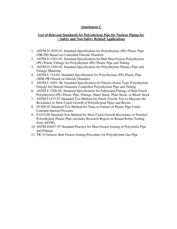
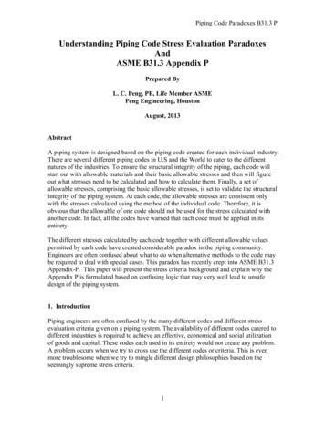
PE Piping Systems OverviewSince its discovery in 1933, polyethylene (PE) has grown to become one of the world’smost widely used and recognized thermoplastic materials. Today’s modern PE resins arehighly engineered for rigorous applications such as pressure-rated gas, recycled water,sanitary and drinking water systems, sustainable energy systems, landfill membranes,automotive fuel tanks and other demanding applications.Figure 1: Complete PE Water SystemSome of the specific benefits of PE pipe are: Life Cycle and Construction Cost Savings – For municipal applications, the lifecycle and construction cost of PE pipe can be significantly less than other pipematerials. Leak-Free, Fully Restrained Joints - PE heat fusion joining forms leak-freejoints that are as strong as, or stronger than, the pipe itself. For municipalapplications, fused joints eliminate the potential leak points. Construction Advantages – PE pipe’s combination of light weight, flexibility andleak-free, fully restrained joints permits unique and cost-effective installationmethods that are not practical with alternate materials. Durability – PE pipe installations are cost-effective and have long-term costadvantages due to the pipe’s physical properties, leak-free joints andreduced maintenance costs.Page 3 of 88
Sizes, Specifications, Pressure RatingsStandard DiametersPE pressure pipe is available in diameters from ½" through 65". Standard specificationsfor PE pipe allow the pipe to be made to either controlled inside diameters or to controlledoutside diameters. The inside diameter system is used for small sizes that use insert typefittings or with special mechanical compression fittings designed for SIDR 7 pipe. Theoutside diameter systems are for use with fusion or with fittings that require a predictableoutside diameter.There is one standard inside diameter sizing convention, SIDR, based on Schedule 40series iron pipe sizes (IPS). There are four standard outside diameter sizing systems: Iron Pipe Sized (IPS) pipe Ductile Iron Pipe Sizes (DIPS) Copper Tubing Sizes (CTS) International Standards Organization (ISO 161/1) pipeStandard Pressure Ratings for WaterTABLE 1Standard Pressure Ratings for Water, at 73 F (23 C), for SDR-PR Pipes, psigStandard Dimension RatioStandard Pressure Rating (psig) as a function of a Material’sHydrostatic Design Stress (HDS) for Water, at 73 F (23 C), psi *SDR (In the Caseof Pipes Made toStandard OD’s)SIDR (In the Caseof Pipes Made toStandard ID’s)HDS 630psiHDS 800psiHDS 1602009.07.0160200250*Test pressures for short-term pressure leak tests can be 1.5 times the listed pressures.Page 4 of 88
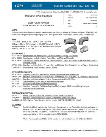
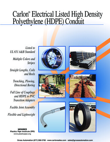
MarkingPipeASTM, AWWA, NSF and CSA standards require that markings on pipe and tubing bepresent at frequent intervals – generally not less than every 5 feet – and that they includeat least the following items of information: The nominal pipe or tubing size (e.g., 1-inch);The type of PE material from which the pipe is made (e.g., PE 4710);The pipe or tubing dimension ratio or the pipe pressure rating or pressure classfor 73 F water, or both;The standard against which the pipe has been made and tested;The manufacturer’s name or trademark;Production record coding the place and time of manufacture; andThe seal or mark of the certification agency that has determined the suitabilityof the pipe for potable water service.Figure 2: Typical Pipe Marking ConfigurationFittingsAt a minimum, all fittings used for PE water service pipe should be clearly marked withthe manufacturer’s name or trademark and the nominal size of the pipe for which they aredesigned. In addition, the seal or mark of the agency that has certified the conformanceof the fitting material to NSF-61 and its suitability for potable water service should bevisible.Page 5 of 88
SAFETY!Flushing and DisinfectingWater piping should be flushed and disinfected in accordance with AWWA C651.Chlorine disinfection, when conducted within the guidelines of AWWA C651, does nothave a significant adverse affect on the performance of PE pipe.Contaminated SoilsWhen water pipelines are installed or repaired in ground known to be contaminated withhydrocarbons, special considerations apply. The AWWA has addressed concernsregarding hydrocarbon permeation by including a permeation statement in all of its pipestandards including standards for PE (C901-07 and C906-07), PVC (C900-07 and C90597), steel (C200-05), ductile Iron (C110-03), and others.Hydrocarbon contamination plumes are relatively compact and usually less than fifty feetin length. If contaminated soils are encountered, do one of the following: Surround the pipe with good clean soil of Class I or Class II materials to allowthe hydrocarbons that may have contacted the pipe’s wall to dissipate into theatmosphere and in the envelope of the surrounding soil. The US EPAguidelines prohibit the reuse of excavated hydrocarbon contaminated soil in theenvelope of bedding or backfill material.Sleeve the pipe in areas where active hydrocarbon contamination is known toexist.Reroute the pipe around the contaminated plume.Hydrocarbons do not degrade polyethylene but can diffuse through the wall of PE pipe inareas of gross contamination. The exterior contact may affect sidewall fusions and orbutt fusions; thus, after PE pipes have been exposed to grossly contaminated soils,mechanical connections may be preferred.General Precautions and PracticesIt is the responsibility of the user of this manual to know and follow safe practices. Obtainand consult specific information from equipment suppliers, authorities with jurisdiction,and applicable regulations and codes, as needed.Page 6 of 88
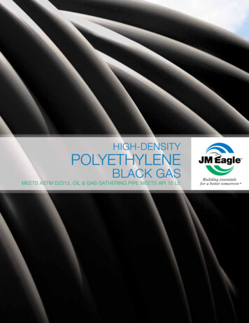
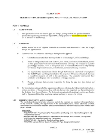
Handling Pipe and FittingsReceivingThe truck must be parked on level ground. The parking brake (hand brake) should be setand the wheels chocked. It is preferred that the truck be shut off and left in gear. Thelocation of the driver should be known at all times.Figure 3: Use Care in Unloading Pipe BundlesGeneral Handling PrecautionsStay Clear Of Trucks Being UnloadedOnly persons directly needed to unload pipe, such as the equipment operator, should beallowed in the vicinity of a truck being unloaded. All others must stay well clear of theunloading area.Slippery When WetPolyethylene pipe is extremely slippery when wet. Use caution at all times, especially inrainy or snowy weather.Hot When Stored OutsideBlack pipe exposed to sunlight may be hot! Always use caution before handling pipe thathas been exposed to direct sunlight.Page 7 of 88
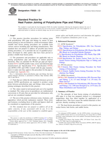
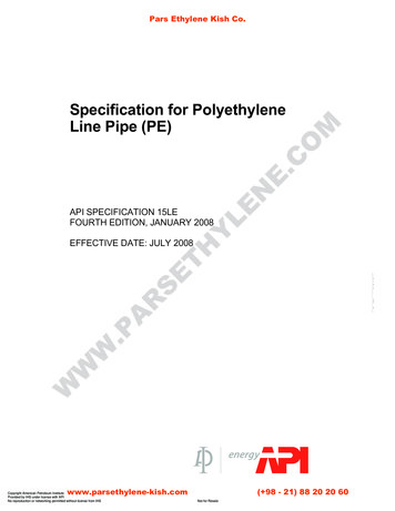
General Handling RecommendationsPower equipment is generally used to handle pipes greater than 8" in diameter. Powerlifting equipment includes forklifts, cherry pickers, backhoes, front-end loaders andcranes. Excessive lengths, high weights or uneven site conditions can require the use ofmultiple pieces of lifting equipment. Only experienced operators should be allowed toutilize power equipment.For lifting loose pipe off rail cars with side stakes, a minimum 15-foot lift is required. Forlifting pipe off trucks with side rails, a minimum 11-foot lift is required.The staging area (operating space) must be clear of workers and obstacles and mustprovide the operator with a clear line-of-sight. Mark off the staging area to alert otherworkers that lifting equipment is being used.Never exceed the rated lifting capacity of the equipment. All equipment specificallydesigned for lifting will be marked with a safe lifting capacity.ForkliftsThe use of forklift trucks necessitates observing a number of OSHA standards. Theproper and safe use of forklifts is the responsibility of the operator. Special procedures forhandling PE pipe are: Check the forks for jagged edges or burrs. If the forks are marred, cover themwith a suitable protective covering to prevent gouging of the pipe;Use the forks in the widest possible position;Always lift from the center of the pipe at the center of the forks;Always slowly enter the forks underneath the pipe; never jerk or ram them in;Tilt back the load only enough to stabilize the load; andOperate as close to the ground as possible when moving pipe from one locationto another, but do not allow the pipe to drag or scrape along the ground.Figure 4: Using a Forklift for Unloading Pipe BundlesPage 8 of 88
Front End LoadersWhen equipped with forks, front-end loaders can be operated as forklifts and the sameprocedures must be followed as indicated above. Typically, front-end loaders are used tolift and move large diameter pipe.Mobile CranesWhen lifting pipe from overhead some additional requirements must be observed. Locateoverhead obstructions such as wires and trees and keep a minimum 10-foot clearance atall times. Obstacles in the trench, meter pit or vault must also be avoided.Inspect rigging for damage. Never swing a load of pipe or fittings over workers or in areasthat are used as pathways for traveling. Operate the crane at constant speed. Avoidjerking and sudden movements.BackhoesBackhoes are often operated as cranes. The hook on the underside of the bucket is usedto lift and transport pipe. The use of backhoes is common since they are almost alwaysavailable on the job site. The same precautions used for cranes must be followed toensure their safe operation.Pipe Handling AccessoriesChains, steel cables, wire ropes and hooks must not be used directly on polyethylenepipe or fittings.SlingsWide band slings distribute the lifting load over a large area and prevent point loading orpipe gouging. They can be used as chokers or with spreader bars. Chokers prevent thepipe or fitting from slipping during lifting. Spreader bars are recommended for lifting longlengths of fused pipe.Nylon RopeThick nylon rope can also be used to lift pipe. It provides support similar to slings. Nylonrope can be used as chokers or with spreader bars.TongsSpecially designed pipe tongs can be used to lift pipe. They provide lifting support as thepipe weight increases. Do not exceed the design capacity.Page 9 of 88
RampsRamps can sometimes be used to lower smaller diameter pipe. Ramps require theoperator to stand to the side and slowly release the pipe down the ramp. Care must beexercised to avoid losing control during the lowering procedure.Lifting RequirementsThe lifting capacity of a sling or rope is determined by several factors including the type ofsling or rope, the kind of hitch used, and how fittings are fastened to them. Typically,accessories should be rated at a minimum of 1.5 times the weight of the heaviest load tobe lifted. The angle between each leg of the sling or rope should not exceed 45 degrees.Avoid kinking or twisting any part of the lifting accessory.Guidelines for Palletized and Non-palletized CoilsThe trailer must be level before straps or bands are removed and the coils unloaded. Donot push, pull or roll coils off of the truck. Never stand behind, under or around the loadas it is being unloaded. Do not remove straps until the sling is secured. If coils are in silosdo not push or pull the silo pack off the end of the truck with a lift truck.Non-PalletizedPalletizedPage 10 of 88
Guidelines for Straight LengthsUnloading Bundles from a Flat-Bed TrailerFigure 5: Use Care in Unloading Bundled Fittings and PipeCheck that the load has not shifted before removing the nylon straps securing the load tothe trailer. Use caution when straightening shifted loads before unloading.Bundles should be unloaded with fork trucks or cranes equipped with spreader bars withat least three wide web slings. If bundles are stacked and individually strapped to thetruck, unload the bulk packs one at a time from the top. Remove only the straps over thepack being unloaded. Steel bands used on bundles should not be removed until thebundles have been transported to the storage area and secured in a stable and safemanner.Never stand on a load of pipe. Do not roll or drop pipe off the truck. Do not use backhoes,end loaders, or other material handling equipment to push or pull the load off the trailer.Unloading Strip Loads from a Flat-bed TrailerWhen unloading with a forklift, a second truck (or some other means) should be placedon the opposite side to the unloading equipment to prevent pipe from being pushed fromthe truck.Page 11 of 88
Strip Loads Using Strip PacksCheck that all steel bands are in place before removing the nylon straps securing theload to the trailer. Unload pipe with fork trucks, cranes equipped with wide web slings, orcranes equipped with spreader bars with wide web slings.If a fork truck is used, the forks should have sufficient length to safely support the strippack. The pack should be approached slowly at the midpoint of the pipe lengths. Toimprove the pack stability during transportation, the forks should be as far apart aspossible.If a crane with a single sling is used to unload the strip pack, the lengths should behandled at their midpoints using wide web slings. If multiple slings or a spreader barequipped with wide web slings are used, the equipment manufacturer’s recommendedmethods and procedures should be used. If the pipe is being unloaded in full rows, do notcut the bands until the row is lowered to the ground; the bands prevent the pipe fromrolling.If the pipe is being unloaded in less than full rows, the bands should be cut and removedonly from the length(s) being unloaded. Any loose pipe in the row should be secured withsuitable wedges. After each layer is off the trailer, remove dunnage from the top of pipe.Strip Loads Using ChocksAssure that all chocks are securely in place on both ends of the timbers. If they are not,nail a chock or other suitable wedge into position. At no time should the chocks ontimbers be removed. The chocks prevent pipe from rolling. Check that all chocks are inplace before removing the nylon trucker straps securing the load to the trailer. Do notremove “belly” straps until unloading is to take place on that layer. Use caution whenstraightening shifted loads before unloading.Pipe should be unloaded with fork trucks or cranes using at least three slings or endhooks. When banded pipe is being unloaded in full or partial rows do not cut the banduntil the pipe is lowered to the ground. After each layer is off the trailer, remove dunnagefrom the top of pipe.Page 12 of 88
StoringBefore pipe and/or fittings are placed into storage, they should be visually inspected forscratches, gouges, discoloration and other defects. Damaged or questionable materialsshould not be put into storage. Cuts and gouges that reduce the wall thickness by morethan 10% may impair long-term service life and should be discarded.Off-Site Storage GuidelinesStore small pipe in racks according to the length and size of the pipe. Block or strap thepipe to prevent it from rolling or falling off the rack. Pipe larger than two inches indiameter should be stacked with spacing strips between each row. Arrange and blockeach row of stacked pipe to prevent it from rolling off the pile. If pipe is stored outdoors,make sure all blocks are made of material that won’t deteriorate as it weathers.Material that cannot be stacked because of its size or shape should be stored on shelvescapable of supporting the combined weight of the materials.Job Site Storage GuidelinesThe storage area should have a relatively smooth, level surface free of stones, debris orother materials that could damage the pipe or fittings. Where adequate ground conditionsdo not exist or when a bed cannot be prepared, the pipe may be placed on plankingevenly spaced along the pipe length.Figure 6: Storing PE PipeWhen pipes of variable wall thickness are received, it is recommended that the pipe besegregated into piles, each pile containing a single size and pressure rating to minimizeconfusion at a later date. The pile should be constructed in a pyramid, with eachsuccessive layer having one less pipe than the layer below. The bottom layer should bebraced to prevent movement.Page 13 of 88
The maximum allowable stacking heights for polyethylene pipe should not exceed thosein Table 2. Pipe coils should be stored upright on skids on a level surface.TABLE 2: Suggested Loose Storage Stacking Heights in Rows for HDPE pipeNominal PE Pipe Size (in)45681012Suggested Stacking Height – RowsAbove DR 17DR 17 & Below15121210108866554Indoor/ Outdoor StorageExpansion and contraction caused by uneven heating during storage in the sun maycause the pipe to bow if not restrained by racks. This does not damage the pipe but maybe inconvenient when the pipe is taken out of storage for installationSince black HDPE pipe generally contains greater than 2% carbon black, it will resistdamage from sunlight indefinitely. Colored products are compounded with antioxidants,thermal stabilizers and UV stabilizers. Therefore, non-black products should remain inunprotected outdoor storage for no more than two years (or longer only as recommendedby the pipe manufacturer). Black products with stripes are generally suitable forunprotected outdoor storage and service.Page 14 of 88
PE Water Service LinesSizes, Pressures, and SpecificationsPE Water Service lines are typically ½" to 3" nominal diameter pipe or tubing inaccordance with AWWA C901, ASTM D2239, ASTM D3035, or ASTM D2737, with ratedpressure of 80 to 250 psig in accordance with Table 1. Water service lines may be joinedto themselves or to other types of pipe or fittings.Options for joining depend on the pipe’s sizing convention:IPS pipe produced per ASTM D3035: Heat Fusion Electrofusion O.D. Mechanical Compression fittings. O.D. Stab fittingso Internal stiffeners are recommended on ½” – 2” stab and mechanical fittingsCTS pipe produced per ASTM D2737: Heat Fusion Electrofusion O.D. Mechanical Compression fittings. O.D. Stab fittingso Internal stiffeners are recommended on ½” – 2” stab and mechanical fittingsSIDR pipe produced per ASTM D2239: Barbed insert fittings and clamps. Double clamping is recommended for pipes 1-1/4” and larger and on pressuresexceeding 160 psi. SIDR 7 pipe may be joined with O.D. Mechanical Compression fittings madespecifically for these pipe sizes.Page 15 of 88
Figure 7: Typical PE Water Service Line ConfigurationFigure 8: Typical All-PE Water Service Line ConfigurationPE Main with SaddleFusion TeeCurb Valve withMechanical CouplingsMeter with PE to BrassTransitionsPE to CopperMechanical FittingPage 16 of 88
BurialPE Water Service lines can usually be installed using basic simplified trenching andbackfill guidelines. Follow all instructions for placement and alignment of pipe andfittings.TrenchingPrepare trenches for PE Water Service lines in accordance with the SimplifiedInstallation Instructions of this Manual. A trench width of 12 inches is generally suitablefor a water service line.Figure 9: Two PE Water Service LinesPlacementPlace the PE Water Service line in a prepared trench that is free of rocks and debris.Place the pipe so that it is relaxed and “snakes” loosely in the trench. Do not bend thepipe more than the minimum bend radius for the DR of the service line.Figure 10: Proper vs. Improper Placement in TrenchPage 17 of 88
Compaction and CoverComplete the compaction and cover of PE Water Service lines in accordance with theSimplified Instructions of this Manual. Do not allow rocks or other hard objects in thevicinity of the buried Water Service line.Connections to MainsThere are many options available for hooking up a PE service line to a main. To help youselect the best option you should consider: Type of installation (new or existing); Type of main (PE, PVC, Ductile Iron, etc.); Type of fittings (mechanical vs. fusion); Type of tap (pressure or non pressure); and Type of PE service line you want to use (SIDR, CTS, and IPS).If a new main is being installed, you have the option to install equal or smaller inline tees,wyes or crosses. If the main is already installed, you may use service saddles, branchsaddles or tapping tees. Mechanical tapping saddles are available for larger diameterpipe branches.If the main is made of Ductile Iron, PVC or Concrete, you must use mechanical fittings. Ifthe main is made from PE, you may use either mechanical fittings or fusion. Fusion is thepreferred method of connecting to a main because, when done properly, fusion joints donot leak.If you are using mechanical saddles or fittings you need to ensure they are designed foruse with polyethylene pipe. The physical characteristics of PE pipe may contribute toleaking joints when used with fittings that are designed for other materials. In addition,mechanical fittings that use screws or bolts that tighten into the wall of the pipe can causepoint loading failures in PE pipe. Fittings that exhibit equal compressive stresses aroundthe wall of PE pipe work best. Consult the fitting manufacturer for recommendations.Another consideration is whether you will be making a live tap or connecting to a nonpressurized line. When making live taps, Self Tapping tees are recommended. Servicesaddles with corp. stops are also effective.Transitioning to the service line is another consideration. You will need to transition fromthe corp. stop or tapping tee outlet to your service pipe. There are many transition fittingsavailable that will allow you to transition from thread on a corp. stop to SIDR, CTS or IPSpipe. Depending on the brand, the outlet on the self tapping tees may be stab, fusion orcompression. Consult the fitting manufacturer.Page 18 of 88
Fusion to PE MainThe examples that follow illustrate connections to mains made at a vertical (90-degree)angle, for clarity. Actual installation angles may vary in accordance with localrequirements or preferences.Saddle Fusion to PE MainConnections of PE Service Lines to PE Mains should be made by saddle fusion or saddleelectrofusion wherever possible.Saddle and Saddle Electrofusion Self Tapping tees may be used to live tap PE pressuremains. The main is prepared based on fusion procedures being followed. The SelfTapping Tee is installed on the main. The cutter is threaded into the main then retracted,retaining the coupon. The PE service pipe is installed on the outlet stub usingmechanical compression or stab fittings or with heat fusion.PE service lines can be installed on pressure or non-pressure PE mains using saddle orsaddle electrofusion service saddles and corporation stops. Prior to installing the saddle,prepare the main based on the fusion method you are following.Prepare the main based on the fusion procedures being followed. Fuse the saddle on themain and install the corp. stop. The tap is done with standard tapping tools andprocedures for either pressure or non pressure mains. The service tubing is installed onthe corp. stop outlet. Transition fittings are available to connect to the threaded outlet onthe corp. stop to PE service line.Saddle or saddle electrofusion Tees can be installed on non pressure PE mains. Themain is prepared based on the fusion procedures you are following. The tee is installed.A tap is manually made in the wall of the main. The PE service line is attached to the teeusing OD mechanical compression fittings or with fusion.Figure 11: Saddle Fusion of PE Water Service Line to MainFollow the procedures for Saddle Fusion given in this Manual to make connections ofWater Service lines to Mains with suitable saddle fusion fittings. Figure 11 shows atypical saddle fusion tapping tee with a PE Water Service line stub.Page 19 of 88
Saddle Electrofusion to PE MainFigure 12: Saddle Electrofusion of PE Water Service Line to MainFollow the procedures for Saddle Electrofusion Fusion given in this Manual to makeconnections of Water Service lines to Mains with suitable saddle fusion fittings. Figure 12shows a typical electrofusion tapping tee with a stab-type connector for the PE WaterService Line.Mechanical Connections MainsMechanical Connection to PE MainsIf fusion tools are not available, Mechanical Tapping tees can be used to tap live PEpressure mains. The tee is securely installed on the main. The cutter is threaded into themain and then retracted, retaining the coupon. The PE service pipe is installed on thetapping tee outlet using stab, compression fittings or fusion depending on the fitting.Figure 13: Mechanical Saddle Connection to PE MainPage 20 of 88
PE service lines can be installed on pressure or non-pressure PE mains usingmechanical service saddles and corporation stops. Use of mechanical saddles andsealing gaskets is recommended in areas with minimal temperature changes. Doublestrapping of the service saddle and sealing gaskets is recommended. Prior to installingthe saddle, inspect the pipe for scratches or damage that might create a leak path.Install the saddle and corp. stop on the main. The tap is done with standard tapping toolsand procedures for either pressure or non-pressure mains. The service tubing is installedon the corp. stop outlet. Transition fittings are available to connect to the threaded outleton the corp. stop. Do not thread any component into the PE pipe wall itself.Mechanical Connection to Non-PE MainsConnections of PE Service Lines to non-PE Mains should be made using mechanicalfittings designed for the specific application and piping materials.Install the mechanical service saddle that is designed for the pipe being tapped per thefitting manufacturer’s instructions. Install the corporation stop. Make the tap. Transitionfittings are available to connect the threaded outlet on the corp. stop to the PE servicetubing.Figure 14: Mechanical Saddle Connection of PE Water Service Line to PVC MainFollow Manufacturer’s instructions to install suitable fittings to connect PE Water Servicelines to non-PE Mains, such as PVC or Ductile Iron. Use only fittings approved andcertified for this application.Page 21 of 88
Water Service Line ConnectionsFusion of PE Water Service LinesFollow the general instruction in this Manual for making butt-fusion and electrofusionconnections in PE Water Service lines. Connection by fusion is the recommendedmethod of joining PE pipe wherever possible. Where mechanical connections arerequired for transitions, terminations, or joining, use fittings and procedures inaccordance with the following section.Mechanical Connection of PE Water Service LinesTerminologyMechanical coupling - a device for joining pipe or tubing that does not require heatfusion or welding and utilizes a gripper ring for restraint and seal/gasket for a leak-freeconnection. Types of mechanical couplings commonly used on HDPE service tubinginclude Insertion (stab) and Compression.Stiffener/Insert - a flanged cylinder of NSF approved material that is inserted into plastictubing to reinforce the gripping and sealing regions.Seal/O-Ring/Gasket - a ring, usually made of an elastomer/rubber, that, whencompressed, creates a leak-tight seal on the HDPE tubing preventing leakage of waterfrom the fitting.Gripper Ring - the plastic component of a coupling that grips or restrains the HDPEtubing preventing pullout from the mechanical fitting.Coupling Body - the pressure bearing vessel that can contain the stiffener, gripper ringand seal/gasket into which the HDPE tubing is inserted.Chamfer – A bevel or angle put onto the HDPE tubing (required in some couplingproducts) that aids the insertion of the tubing into the coupling or fitting body.Compression Coupling - a type of mechanical co
Construction Advantages – PE pipe’s combination of light weight, flexibility and leak-free, fully restrained joints permits unique and cost-effective installation . Do not exceed the design capacity. Page 10 of 88 Ramps Ramps can sometimes be used to lower