Transcription
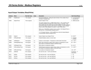
KN Series Boiler - Modbus Registersv2.22Input/Output Variables (Read/Write)AddressNameRaw Data TypeScaleDescriptionValid Values/Range40001HeatDemand1 bit unsigned---Heat Demand/Request. Setting the state member of this variable will putthe boiler in heating mode.0 no heat demand1 heat demand40002SetpointTimer16 bit unsigned---System Setpoint Timer0 – 65535 secondsThe system setpoint timer is a BMS failsafe feature. This countdown timershould be periodically reloaded with a timeout value (in seconds). If thetimer reaches zero, the control assumes that the BMS is no longer operatingand the local setpoint (saved on the control) is reloaded. This is a failsafefeature used to help safeguard the system in case of BMS failure.When any (1) Read/Write variable is timer is written, if the SetpointTimer isless than 60, it is automatically reloaded with 60.(1) In Firmware Versions 3.48, the BMS has to write the SystemSetpointto automatically reload the SetpointTimer.40003Setpoint8 bit unsigned1.0System Setpoint (see SetpointTimer)40 - 220 F40004OAResetEnable1 bit unsigned---Enables/Disables outdoor air reset mode.0 disabled1 enabled40005OARSetpoint16 bit signed1.0Outdoor air reset setpoint. Temperature at which boiler shuts down.40 – 100 F40006OARHighWaterTemp16 bit signed1.0Boiler water temperature setpoint when outdoor air temperature is at thehigh outdoor air temperature setpoint (OARHiAirTemp).60 – 150 F40007OARHighAirTemp16 bit signed1.0High outdoor air temperature setpoint.50 – 90 F40008OARLowWaterTemp16 bit signed1.0Header/Supply temperature setpoint when outdoor air temperature is at thelow outdoor air temperature setpoint (OARLoAirTemp).70 – 220 F40009OARLowAirTemp16 bit signed1.0Low outdoor air temperature setpoint.-35 – 40 F40010SetMonth8 bit unsigned---Set real time clock – month (see SetClock)0 (January) - 11(December)40011SetDay8 bit unsigned---Set real time clock – day (see SetClock)1 – 3140012SetYear8 bit unsigned---Set real time clock – year (see SetClock)0 – 9940013SetHour8 bit unsigned---Set real time clock – hour (see SetClock)0 – 23 2007-2011 Mestek, Inc.Page 1 of 15
KN Series Boiler - Modbus Registersv2.22AddressNameRaw Data TypeScaleDescriptionValid Values/Range40014SetMinute8 bit unsigned---Set real time clock – minute (see SetClock)0 – 5940015SetSecond8 bit unsigned---Set real time clock – second (see SetClock)0 – 5940016SetWeekday8 bit unsigned---Set real time clock – weekday (see SetClock)1 (Monday) - 7 (Sunday)40017SetClock1 bit unsigned---Set (write) the real time clock.0 no action1 set/write the clockTo write the real time clock, the system variables (SetMonth, SetMonth,SetDay, SetYear, SetHour, SetMinute, SetSecond, SetWeekday) must firstbe loaded with the correct date and time. Then, a 1 must be written to thestate portion of this system variable to write the new date and time to thesystem clock.----- The following registers are available starting in firmware version 3.48 ----40018DHWSetpoint 2007-2011 Mestek, Inc.16 bit signed1.0DHW Setpoint40 - 200 FPage 2 of 15
KN Series Boiler - Modbus Registersv2.22Input Variables (Read Only)AddressNameRaw Data TypeScaleDescriptionValid Values/Range30001BoilersOn8 bit unsigned---The number of boilers currently running.0 – 1630002Modulation8 bit unsigned0.01Current system (target) modulation level. This is the modulation level thatthe system is trying to run at to meet the heating demand.0 – 100 %30003HeaderTemp16 bit signed0.01Header / System temperature.32 – 250 F30004SupplyTemp16 bit signed0.01Supply temperature.32 – 250 F30005ReturnTemp16 bit signed0.01Return temperature.32 – 250 F30006OutsideTemp16 bit signed0.01Outside air temperature.-40 – 250 F30007Spare116 bit signed---Raw A/D value from spare 1 input.-32768 to 32767DHW Temp16 bit signed0.01DHW Sensor Temperature32 – 250 F30008Spare216 bit signed---Raw A/D value from spare 2 input.-32768 to 3276730009Month8 bit unsigned---Real time clock month.0 (January) - 11 (December)30010Day8 bit unsigned---Real time clock day.1 – 3130011Year8 bit unsigned---Real time clock year.0 – 9930012Hour8 bit unsigned---Real time clock hour.0 – 2330013Minute8 bit unsigned---Real time clock minute.0 – 5930014Second8 bit unsigned---Real time clock second.0 – 5930015Weekday8 bit unsigned---Real time clock weekday.1 (Monday) – 7 (Sunday)30016Boiler01Status116 bit unsigned---30017Boiler01Status2Boiler (1 – 16) status1 and status 2 flags. These bits indicate the state ofvarious boiler statuses.See the BoilerStatus1 Flagsand BoilerStatus2 Flags inAppendix s1 2007-2011 Mestek, Inc.Boiler01 Master or “Connected Boiler”Boiler02 Member01 Boiler16 Member15Page 3 of 15
KN Series Boiler - Modbus 30047Boiler16Status230048Boiler01RuntimeHigh16 2007-2011 Mestek, Inc.Raw Data TypeScale16 bit unsigned---v2.22DescriptionValid Values/RangeBoiler (1 – 16) Runtime seconds High (Upper) and Low (Lower) 16 bit0 – 4294967295 secondsPage 4 of 15
KN Series Boiler - Modbus meLow1630074Boiler14RuntimeHigh16 2007-2011 Mestek, Inc.Raw Data TypeScaleDescriptionv2.22Valid Values/Rangecounters. To get the actual runtime for any given boiler (##), the high andlow 16 bit counters must be combined (concatenated) into a single 32 bitcounter leBoiler01Runtime (Boiler01RuntimeHigh16 * 65536) Boiler01RuntimeLow16Boiler01 Master or “Connected Boiler”Boiler02 Member01 Boiler16 Member15Page 5 of 15
KN Series Boiler - Modbus 95Boiler16Status3Raw Data TypeScale16 bit unsigned---v2.22DescriptionValid Values/RangeBoiler (1 – 16) status3 flags. These bits indicate the state of various boilerstatuses.See the BoilerStatus3 Flagsin Appendix A.Boiler01 Master or “Connected Boiler”Boiler02 Member01 Boiler16 Member15----- The following registers are available starting in firmware version 2.0 30098Boiler03SupplyTemp30099Boiler04SupplyTemp 2007-2011 Mestek, Inc.16 bit signed0.01Boiler (1 – 16) supply temperature (if available). See BoilerStatus2 todetermine if the sensor is present.32 – 250 FBoiler01 Master or “Connected Boiler”Boiler02 Member01 Page 6 of 15
KN Series Boiler - Modbus Boiler14ReturnTemp 2007-2011 Mestek, Inc.Raw Data TypeScaleDescriptionv2.22Valid Values/RangeBoiler16 Member1516 bit signed0.01Boiler (1 – 16) return temperature (if available). See BoilerStatus2 todetermine if the sensor is present.32 – 250 FBoiler01 Master or “Connected Boiler”Boiler02 Member01 Boiler16 Member15Page 7 of 15
KN Series Boiler - Modbus ow16 2007-2011 Mestek, Inc.Raw Data TypeScale16 bit unsigned---v2.22DescriptionValid Values/RangeBoiler (1 – 16) Cycles High (Upper) and Low (Lower) 16 bit counters. Toget the actual cycle count for any given boiler (##), the high and low 16 bitcounters must be combined (concatenated) into a single 32 bit counter as:0 – ExampleBoiler01Cycles (Boiler01CyclesHigh16 * 65536) Boiler01CyclesLow16Boiler01 Master or “Connected Boiler”Boiler02 Member01 Boiler16 Member15Page 8 of 15
KN Series Boiler - Modbus 4Boiler15Status430175Boiler16Status4Raw Data TypeScaleDescriptionv2.22Valid Values/Range----- The following registers are available starting in firmware version 3.48 ----- 2007-2011 Mestek, Inc.16 bit unsigned---Boiler (1 – 16) status4 flags. These bits indicate the state of various boilerstatuses.See the BoilerStatus4 Flagsin Appendix A.Boiler01 Master or “Connected Boiler”Boiler02 Member01 Boiler16 Member15Page 9 of 15
KN Series Boiler - Modbus RegistersAddressNameRaw Data Type30176 30207RESERVED---30208Boiler01DHWTemp16 bit oiler07Modulation30231Boiler08Modulation 2007-2011 Mestek, Inc.Scalev2.22DescriptionValid Values/Range------------Boiler (1 – 16) DHW temperature (if available). See BoilerStatus4 todetermine if the sensor is present.32 – 250 FBoiler01 Master or “Connected Boiler”Boiler02 Member01 Boiler16 Member1516 bit signed---The running (“display”) modulation. This is typically the actual runningmodulation except under special circumstances when the boiler is runningin a self-protection mode (Op. Limit, ½ Fire Rate, etc.)0 - 100Boiler01 Master or “Connected Boiler”Boiler02 Member01 Boiler16 Member15Page 10 of 15
KN Series Boiler - Modbus tion30240OperatingSetpoint 2007-2011 Mestek, Inc.Raw Data Type16 bit signedScale---v2.22DescriptionValid Values/RangeThis is the current operating or active setpoint. It may be:1) The normal heating setpoint.2) The DHW setpoint if running in DHW mode.3) A calculated setpoint if running in Outdoor Air Reset Mode4) The 4-20ma (0-10V) setpoint.40 - 220 FPage 11 of 15
KN Series Boiler - Modbus Registersv2.22APPENDIX A – Status FlagsBoilerStatus1 FlagsBitDescriptionValid Values/Range0Pilot Valve0 closed, 1 open1Blower Running0 off, 1 on (running)2Ignition Alarm0 ok, 1 alarm3IRI Alarm0 ok, 1 alarm4High Limit0 ok, 1 tripped5Air Prove Switch0 proven, 1 not proven6------7Software Operator Tripped0 not tripped, 1 tripped8Header Sensor not detected0 detected, 1 not detected9Supply Sensor not detected0 detected, 1 not detected10Return Sensor not detected0 detected, 1 not detected11Outside Sensor not detected0 detected, 1 not detected12System Pump Running0 off, 1 on (running)13Combustion Air Damper Prove0 not proven, 1 provenObsolete – Available only on revision 1.x controls.14Master Boiler0 member, 1 master15Boiler Detected0 not detected, 1 detectedA boiler was detected at this address. 2007-2011 Mestek, Inc.Page 12 of 15
KN Series Boiler - Modbus Registersv2.22BoilerStatus2 FlagsBit0DescriptionValid Values/RangeDisabled0 enabled, 1 disabledThe boiler is disabled. For instance, when minimum off time has not been met.1Local Override (member boilers only)0 no override, 1 overrideState of the local override (Heat Demand) input on member boilers.2Alarm0 ok, 1 alarmAn alarm or warning condition has occurred. An attempt(s) will automatically be made to recover andresume normal operation.3Failed0 ok, 1 failedA condition has occurred under which the boiler can no longer run.4Member Error0 ok, 1 errorAn “Alarm” or “Failed” condition has occurred on one (or more) of the member boilers.5Boiler Running0 off, 1 running6Local Pump Running0 off, 1 running7System Water Prove (Flow) Interlock.0 open, 1 closedThis input was previously called “Spare 3”.8LWCO Interlock (Low Water Cut Off)0 open, 1 closed9VFD Interlock (Variable Frequency Drive)0 open, 1 closed10Gas Prove Interlock0 open, 1 closed11Spare 4 (User) Interlock0 open, 1 closed12Operator Interlock0 open, 1 closed13Local Water Prove (Flow) Interlock0 open, 1 closed14UV Sensor Air Prove Interlock0 open, 1 closed15Main Valve0 closed, 1 open 2007-2011 Mestek, Inc.Page 13 of 15
KN Series Boiler - Modbus Registersv2.22BoilerStatus3 FlagsBitDescriptionValid Values/Range0AA High Fire Input0 off, 1 on1Heat Demand Input (Local Override)0 off, 1 on (1)24-20ma Remote Enable Input0 off, 1 on3Outdoor Air Reset Override Input0 off, 1 on4T1 Input0 off, 1 on5T2 Input0 off, 1 on6T3 Input0 off, 1 on7T4 Input0 off, 1 ------15------ 2007-2011 Mestek, Inc.Page 14 of 15
KN Series Boiler - Modbus Registersv2.22BoilerStatus4 FlagsBit0DescriptionValid Values/RangeDHW Enabled (1)0 off, 1 on (menu)DHW Mode had been enabled in the menus.1Combustion Air Damper Prove (1)0 not proven, 1 provenStatus of Combustion Air Damper Prove Input J12B2Call Service Fault (1)0 off, 1 on3Air Switch (Blower) Fault (1)0 off, 1 on4------5------6------7------8------9DHW Sensor not detected (1)0 detected, 1 not detected10DHW Boiler (1)0 no, 1 yes (DHW jumper cut)This control board has been designated a DHW boiler by cutting the DHW jumper (JPS1).11Operating Limit Clamp (1)0 off, 1 clampedBoiler input is being limited (clamped) due to a high supply (outlet) temperature.12------13------14------15------(1) Available in Firmware Version 3.48 . 2007-2011 Mestek, Inc.Page 15 of 15
KN Series Boiler - Modbus Registers v2.22 2007-2011 Mestek, Inc. Page 2 of 15 Address Name Raw Data Type Scale Description Valid Values/Range