Transcription
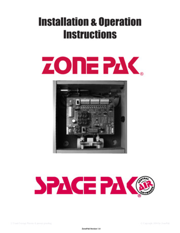
Installation & OperationInstructionsU.S and Foreign Patents & patents pending ZonePak Version 1.0 Copyright 2008 by ZonePak
Installation PrecautionsThis Zoning System must be installed by a qualified HVAC Contractor!Caution - Electrical HazardCan cause personal injury or equipment damage. Disconnect power to HVAC system before beginning installation.WHEN INSTALLING THIS PRODUCT.6. Complete the Commissioning Checks (p. 8) afterinstallation is complete.1. Read these instructions carefully. Failure to followthem could damage the ZonePak Zoning System 7. The ZonePak Zoning System controls the HVACand/or cause a hazardous condition.equipment via a set of dry-contact relays. Besure that this is compatible with the equipment2. Disconnect power supply to the HVAC systemoperating specifications.and the ZonePak system before making anywiring connections to prevent danger of electrical8. All wiring must comply with all applicable electricalshock and equipment damage.codes, ordinances and regulations.3. The ZonePak System is designed for indoor useonly.9. Use properly grounded tools. Wear safety glassesand gloves when drilling or cutting sheet metalducts, fiber glass or any hard objects.4. You must touch a grounded metal objectbefore handling the ZonePak Control Panel toavoid potential loss of internal programs, due to 10. Panel contains both AC and DC Terminals.See Equipment Notes (pp. 6 and 7) for moreelectrostatic discharge.details.5. Install in ambient temperature between 40 and11. Leave these instructions with installed system for150 F, in a non-condensing area.future use.FEATURES1. The ZonePak Zoning System uses a 8. “FAN ON HEAT” switch generates fan callself-contained, low-pressure air pump toactuate dampers.anytime there is a call for heat: typically usedwith hydronic coils or electric heat.2. All zones have full-function control of heating,9. Manual Pump Switch (MPS ) is provided to startcooling and fan capability from their respectivethe pump manually and open all the zone dampersthermostats.for check out purposes.3. The ZonePak Zoning System is both heat/cool 10. Dampers remain open in the last zone that calledand heat pump compatible.for service to take advantage of additional energyefficiency by expelling all conditioned air to the4. Use any standard 24VAC /manual changeover or wireless.11. LEDs indicate all system operations.6. Emergency Heat changeover (manual switch or 12. A 40VA, 24VAC, self-resetting, plug-in typeremote outdoor thermostat) for heat pumptransformer is provided to power the control panelbalance point changeover from heat pump toand thermostats.backup heat functions.7. Compressor timed off control (delay on break).When the compressor is turned off, it cannotrestart for four (4) minutes. This feature allowsthe refrigerant pressure to balance beforerestarting.U.S and Foreign Patents & patents pending ZonePak Version 1.0 Copyright 2008 by ZonePak
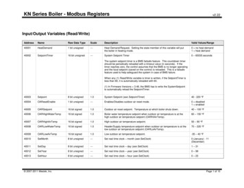
General Operation InformationThe mini-pump, 1 located in the bottom of the enclosure, runs anytime there is a call from any thermostat. Itcreates both pressure and vacuum. On a call from any thermostat, the logic board will energize the 2 solenoidvalve(s) for non-calling zone(s) and close the appropriate 3 dry contact relays to start the HVAC equipment.Dampers open with vacuum.Dampers close with pressure.2The logic board is designed for heating to have priority over cooling and coolingto have priority over fan operation.When all thermostats are satisfied, the air pump, the HVAC equipment and thesolenoid air valves are de-energized. Dampers will remain in whatever positionthey were in when the last thermostat call was finished. Leaving the dampersopen in the last zone served allows the HVAC system to utilize the residualenergy in the system at the end of both the heating and cooling cycles.The Manual Pump Switch (MPS ) is provided to run the pump continuously.Turning the MPS switch to ON manually closes the pump relay and the pumpstarts, driving all dampers open. This creates a failsafe. If the board fails thedampers can be easily opened and the system run from one thermostat.31Equipment NotesTHERMOSTATSThe ZonePak Zone Control is compatible with any standard 24VAC thermostat: programmable/non-programmableauto/manual changeover or wireless.If the thermostat has an adjustable heating anticipator (mechanical thermostats), set it to the shortest or lowestsetting.Heat pump thermostats are required for heat pump operation.Set up the thermostat to call Y,G in heating: Y,G,O in cooling.LEAVING AIR TEMPERATURE CONTROLSThe ZonePak Zone Control does not monitor the temperature of the air in the ductwork. If positive control isdesired, additional temperature controls must be installed.U.S and Foreign Patents & patents pending ZonePak Version 1.0 Copyright 2008 by ZonePak
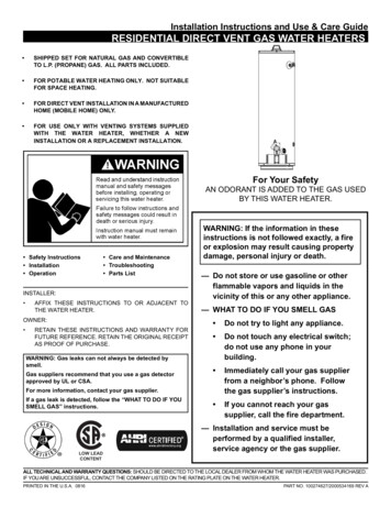
Quick Start InstructionsThe ZonePak Zoning System is easy to install. Please read these instructions completely to ensure that youunderstand the system. Pay special attention to the Caution Statment Section on Page 2. This QuickStartpage has been provided as an installation overveiw with references to more detailed information other placesin this manual.1 Install Dampers/Run TubingDampers install directly into existing ductwork. Dampers install with the tubing portpointing toward the equipment. Install one tubing run for each zone. Use a teefor multiple dampers on one zone. ZonePak recommends using a different colortube for each zone. Install sheet metal sleeve when installing in duct board.2 Mount PanelPanel must be mounted in a non-condensing area where temperatures will notonormally exceed 150 F. DO NOT MOUNT PANEL ON DUCTWORK OR THEHVAC EQUIPMENT. The best method is to attach a piece of 3/4” plywood to ablock or stud wall. Hold the panel level to the wall, mark the positions of the uppermounting holes. Drive two screws to the wall leaving the heads at least 1/2” out.Set the panel over the screws. Drive two screws into the lower mounting holes.Tighten the upper screws.3 Connect ThermostatsInstall a thermostat for each zone. Use 18 gauge, multi-conductor, solid thermostat wire to connect the thermostatsto the control panel. Touch a mechanical ground to discharge static electricity. Connect R,W,Y,G,O, and C asappropriate to the zone terminal strips along the top of the control panel. Note which thermostats are connectedto which zones on the zone layout label on the side of the enclosure.4 Connect EquipmentUse 18 gauge, multi-conductor, solid thermostat wire to connect the HVAC outputs along the left side of thecontrol panel to the HVAC Equipment. Connect R,W,Y,G, O, and C as appropriate to the equipment as if thecontrol panel were a thermostat.5 Connect TransformerUse 18 gauge - 2- conductor solid wire to connect R and C on the 24VAC power terminal strip to the mountingscrews on the 40VAC self-resetting, plug-in transformer supplied with the ZonePak Zoning System. Plug inthe transformer to any standard 120VAC receptacle.6 Test the SystemSee commissioning procedure on pg. 8.24VAC TransformerConnections40VA Y,G, Oand C asnecessaryHVAC EquipmentConnectionsDry ContactsR,W,Y,G, O and Cas necessaryU.S and Foreign Patents & patents pending ZonePak Version 1.0 Copyright 2008 by ZonePak
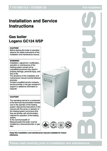
Wiring DiagramsThe following diagrams have been provided for your convenience. They represent the most common installationtechniques. If your application does not look like either of these or you need additional help, there are additionaldiagrams at www.SpacePak.com or contact technical support at (866)325-5107.Zone urnace/FanCenterZone 3ThermostatZone 2ThermostatRWYGOC18-5 Thermostat wireZone 2RWYGOCZone 3RWYGOCR W YGO C18-4 or 18-5Thermostat wireRemoteODTHVAC Outputs 24VACR W YG OB C RCZone 1RWYGOCONMPSOFFPump 1 2 3 Pump and Solenoid connections(factory installed)PumpChoose thermostats that energize the O terminal in coolingHeat Pump withElectric BackupZone 1ThermostatZone 2ThermostatRWYGOCRWYGOC18-5 or 18-6Thermostat wireZone 2RWYGOCZone 3RWYGOCReversing ValveSelect the HVAC OutputO terminal if your reversing valveenergizes in cooling,B terminal if it energizes in heatingU.S and Foreign Patents & patents pendingRemoteODTHVAC Outputs 24VACR W YG OB C RCZone 1RWYGOCR W YGO CRWYGOC18-5 Thermostat wire24VACTransformerHeat PumpZone 3ThermostatONMPSOFFOutdoorThermostatorComN/OSPST RelayComEN/OCLoad side Coil sidePump 1 2 3 Pump and Solenoid connections(factory installed)Connect relay coil toE & C from any singlethermostatPump ZonePak Version 1.0 Copyright 2008 by ZonePak
Circuit Board Layout & Equipment Notes3214567LED Display n/Off w/LED224VAC TerminalsThe ZonePak System is powered by a 40 VA 24VAC transformer (provided). This switch and theHVAC system equipment power switch must always be in the “OFF” position when connecting wiresto any terminals.(See Caution Statement page 2)The ZonePak 40 VA transformer (provided) must be connected to these two terminals.Output to the HVAC equipment is controlled by a set of dry-contact relays. The HVAC “R” signal isswitched and sent out to start the appropriate equipment when called by any zone thermostat however completely isolated from the thermostat power supply. (Connect hot or side of HVAC equipment transformer (24 VAC) to this terminal.)R Connect to W1 of furnace. (Aux. heat terminal if heat pump is installed.)3HVAC OutputTerminalsW Connect to compressor contactor.Y Connect to equipment fan relay.G Connect either “O” or “B” to heat pump reversing valve, as required by heat pumpmanufacturer.O/B Use the “O” signal if the unit reverses in the cooling cycle; the “B” if it reverses in the heatingcycle.C Connect common side of HVAC equipment transformer (24 VAC) to this terminal.4Thermostat TerminalsConnect thermostat wires (R,W,Y,G,O, and C) as required for your application.Note which thermostats are connected to which zones. (24VAC)U.S and Foreign Patents & patents pending ZonePak Version 1.0 Copyright 2008 by ZonePak
56ODTTerminalsEmergency HeatSwitchEmergency Heat changeover terminals “REMOTE ODT” (5VDC) are used for remote switching byoutdoor thermostat. This remote switch (or thermostat) will change heat pump operation to backupheat or fossil fuel. If a heat pump is installed with a fossil fuel furnace (without fossil fuel kit) do notconnect the (W) wires from the zone thermostats.Emergency Heat changeover switch, is used to manually bypass the heat pump and energize theauxiliary heat on a call for service (heat pump application only).7Fan-on-HeatSwitchThis switch in the “ON” position will provide automatic fan operation on a call for heating for electricfurnaces, hot water coils, steam coils, etc.8S1,S2,S3Solenoid LEDs9Fault Code LEDsF1,F2,F310PMP LED11Comp LockoutLED12TDOTime DelayOverrideThis momentary contact, Time Delay Override switch (TDO), is provided on the PC board to speed thecheckout of the zoning system. Before using this TDO switch, you must disconnect the HVAC “R” wirein order to avoid short cycling the equipment. The “COMP LOCKOUT” LED (Red) light will indicate 4minute compressor lockout condition.13System StatusLEDsThe “DISPLAY SELECT” switch controls what information is displayed on the Service LEDs.By default the LEDs indicate the HVAC Output Signal. It will illuminate the “Out” LED and the appropriate service LEDs to indicate the call to the equipment.14Display SelectSwitchPush the button once and the system illuminates the Zone 1 (Z1) LED and shows what the Zone 1Thermostat is calling for. Push it again and The Zone 2 (Z2) LED illuminates and the display LEDsshow what Zone 2 is calling for. Push the button a third time and Zone 3 is displayed. Pushing it afourth time will return it to the output display.These LEDs indicate which zones are being served and their zone dampers are open.[S1,S2,S3(Red)]The 3 Fault Code LEDs illuminate when a themostat sends an illegal call. A call is illegal if it isimproper for the type of HVAC equipment installed. LED will stay lit until the power switch is cycled.F1 illegal call on zone 1.F2 illegal call on zone 2.F3 illegal call on zone 3.Illegal calls are ignored. The system will continue to operate normally, serving any legal calls. Illegalcalls may indicate a thermostat or wiring fault in the affected zone.Pump LED (Red) light is ON anytime the pump is running.Compressor lockout LED. Any time the zoning system turns the compressor off it holds it off forfour(4) minutes. This prevents short cycling the compressor.The system will revert to displaying the Output signal anytime the button is idle for 1 s andPump Terminals17MPS SwitchThis switch sets the operational mode for the zoning system. Set the switch for the type of equipment that the zoning system is controlling.Factory connection for the Zone Solenoids (24VDC) . Solenoids are energized to provide pressure toclose the dampers and de-energized to provide vacuum to open the dampers.Factory connections for the pressure/vacuum pump.(24VAC) The pump operates only when a thermostat calls for a heat/cool or fan operation or when the MPS switch is in the ON position.MPS switch starts pump and opens all zone dampers when Power Switch is OFF.U.S and Foreign Patents & patents pending ZonePak Version 1.0 Copyright 2008 by ZonePak
Commissioning ProcedureFAN CHECK-OUT . Set all thermostats to the OFF position and all fan switches to AUTO. . Turn the HVAC system and the ZonePak system PWR switches to ON. The LED light next to the switch willilluminate on the ZonePak control panel.3. Turn the Zone 1 thermostat fan switch ON. The S1 indicator, the Fan output (G) and Pump LED lights will illuminate.The fan in the HVAC system will turn on. The pump and solenoids will position all the dampers. Check the airflow at all register outlets to determine that only Zone 1 dampers are open and all other dampers are closed.4. Follow the above procedure for all other zones.HEATING & COOLING CHECK-OUT . Set all thermostats to the OFF position and all fan switches to AUTO before starting heating system check out. . Set Zone 1 thermostat to the HEAT position and turn thermostat up so that the thermostat is calling for heat.The S1 indicator, the W output, and the pump LED lights will illuminate. The pump and solenoids will positionall the dampers. Check to see that the heating circuit is energized. If heat pump is installed, check operationof Emergency Back-up heating. Turn the thermostat down until the thermostat is satisfied. The LED lights willgo out and the pump will stop. Dampers will remain open in the last zone that called. For heat pump, LEDindication will be Y & G.3. Set thermostat for Zone 1 to the COOL position. Turn thermostat down so that the thermostat is calling for cooling.The S1 indicator, the Y and G outputs and the pump LED will illuminate. The pump and solenoids will positionall the dampers. Check to see that the compressor contactor is energized. For heat pump, LED indication willbe Y, G & O.4. Place Zone 1 thermostat in the OFF position.5. Follow the above procedure for all other zones.IF ALL ELSE FAILS.1. Turn the ZonePak power switch to OFF.2. Disconnect the thermostat wires from any zone and connect them to the HVAC OUTPUT terminals.3. Turn the ZonePak switch ON, this will open ALL zone dampers.The HVAC system will work without the benefit of the zoning system. The heating and air conditioning equipment isnow controlled by that thermostat. All dampers will stay open. If the HVAC system does not work in this configuration,you probably have a wiring, thermostat or other equipment problem.Troubleshooting MatrixProblemPossible CausesCorrectionNo LEDs lit1- Power Switch OFF2- No 24VAC from transformerTurn Power Switch to ON.Check Transformer input/output. Replace if 110V is present w/ no 24vacoutput.Dampers notopening orclosing1- InsufficientPressure/Vacuum2- Binding on rectangular ductCheck for open tube ends or leaky damper actuator.Cut opening to specified dimension per installation instructions.HVAC systemnot operating1- No equipment control power2- Output relay failureCheck equipment transformer and/or control wiringCheck continuity between “R” and calling circuit (W,Y,G) at the HVAC Output, if none and the appropriate output LED is lit, replace board.One zone notbeing served1- Illegal call at panel2- Faulty board componentCheck wiring of thermostat to Panel (“O” is energized with cooling callonly).If call is legal and no service provided, replace PC boardSlave zone notoperatingNo Common wire from equipment control transformerConnect “C” from equipment to “C” of HVAC Output terminals in panel.Low air flow tozones1- Bypass Damper Open2- Restriction in systemAdjust weight on bypass damper for maximum static to smallest zone.Check filter, DX-coil, or secondary heat exchanger coil for blockage.For additional technical support, please call: 866-325-5107U.S and Foreign Patents & patents pending ZonePak Version 1.0 Copyright 2008 by ZonePak
control panel were a thermostat. 2 Mount Panel Panel must be mounted in a non-condensing area where temperatures will not normally exceed 150o F. DO NOT MOUNT PANEL ON DUCTWORK OR THE HVAC EQUIPMENT. The best method is to attach a piece of 3/4" plywood to a block or stud wall. Hold the panel level to the wall, mark the positions of the upper