Transcription
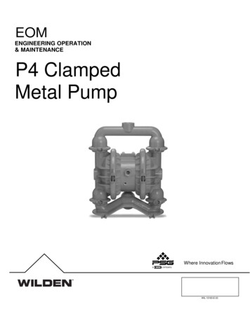
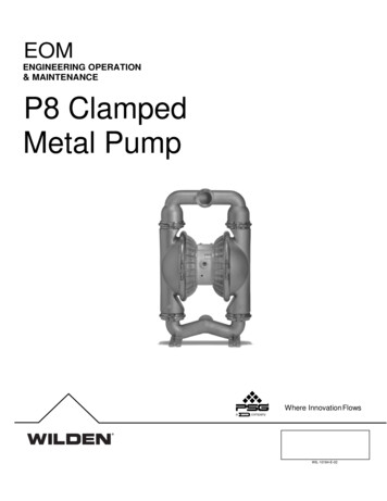
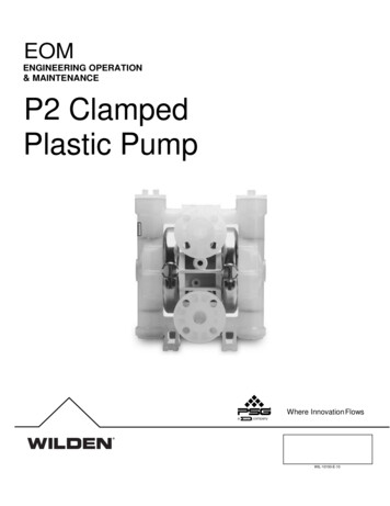
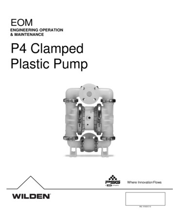
EOMENGINEERING OPERATION& MAINTENANCET15 ClampedMetal PumpWhere Innovation FlowsWIL-10252-E-01
ContentsSection 1: Precautions - Read First!4Section 2: Wilden Pump Designation System5Section 3: How It Works6Section 4: Dimensional Drawings7Section 5: Performance8T 15 M eta l Ru bber - F it ted8T 15 M eta l T P E- F it ted8T 15 M eta l PT F E- F it ted9Su ct ion - Li ft Ca pab il it y10Section 6: Suggested Installation, Operation,11Maintenance and TroubleshootingSection 7: Disassembly / Reassembly14Pu mp Di sa ss emb ly14Ai r Va lve D is as sem bl y17Gas ke t Ki t I ns tal la tio n19Section 8: Exploded View and Parts List21T 15 M eta l Ru bber /T P E - F i t ted21T 15 M eta l PT F E - F it ted25Section 9: Elastomer OptionsWIL-10252-E-01272Wilden
CopyrightCopyright 2018 PSG , a Dover Company. All rights reserved.PSG reserves the right to modify the information and illustrations in this document without prior notice. Theproduct described in this document is furnished under a license agreement or nondisclosure agreement. Nopart of this document may be reproduced, stored in a retrieval system, or transmitted in any form or anymeans electronic or mechanical, including photocopying and recording, without the written permission of PSG,a Dover Company, except as described by the terms of those agreements.This is a non-contractual document. 01-2019.TrademarksPSG and the PSG logo are registered trademarks of PSG. Wilden is a registered trademark of PSGCalifornia LLC. Pro-Flo SHIFT and Pro-Flo are registered trademarks of PSG California LLC. Wil-Flex is atrademark of PSG California LLC. Saniflex is a trademark of PSG California LLC.All trademarks, names, logos and service marks (collectively "trademarks") in this document are registeredand unregistered trademarks of their respective owners. Nothing contained in this document should beconstrued as granting any license or right to use any trademark without the prior written permission of thetrademark owner.WarrantyEach and every product manufactured by Wilden is built to meet the highest standards of quality. Every pumpis functionally tested to insure integrity of operation. Wilden warrants that pumps, accessories and partsmanufactured or supplied by it to be free from defects in material and workmanship for a period of five (5)years from date of installation or six (6) years from date of manufacture, whichever comes first.For more information, and to register your Wilden pump for warranty, please en
Section 1Precautions - Read First!CAUTION: Before any maintenance or repair isattempted, the compressed air line to the pump shouldbe disconnected and all air pressure allowed to bleedfrom pump. Disconnect all intake, discharge and airlines. Drain the pump by turning it upside down andallowing any fluid to flow into a suitable container.TEMPERATURE LIMITS:NeopreneBuna-NEPDMFKMWil-Flex PolyurethaneSaniflex PTFEFlouoro-Seal –17.8 C to 93.3 C–12.2 C to 82.2 C–51.1 C to 137.8 C–40 C to 176.7 C–40 C to 107.2 C12.2 C to 65.6 C–28.9 C to 104.4 C–28.9 C to 148.9 C0 F to 200 F10 F to 180 F–60 F to 280 F–40 F to 350 F–40 F to 225 F10 F to 150 F–20 F to 220 F–20 F to 300 FCAUTION: Blow out air line for 10 to 20 secondsbefore attaching to pump to make sure all pipe linedebris is clear. Use an in-line air filter. A 5μ (micron)air filter is recommended.NOTE: Tighten clamp bands and retainers prior toinstallation. Fittings may loosen during transportation.NOTE: Not all materials are available for all models. See "Wilden PumpDesignation System " on page 5 for material options for your pump.NOTE: When installing PTFE diaphragms, it isimportant to tighten outer pistons simultaneously(turning in opposite directions) to ensure tight fit.CAUTION: When choosing pump materials, be sure tocheck the temperature limits for all wetted components.Example: FKM has a maximum limit of 176.7 C (350 F) butpolypropylene has a maximum limit of only 79 C (175 F).NOTE: Before starting disassembly, mark a line from eachliquid chamber to its corresponding air chamber. This linewill assist in proper alignment during reassembly.CAUTION: Maximum temperature limits are based uponmechanical stress only. Certain chemicals will significantlyreduce maximum safe operating temperatures. Consultengineering guide for chemical compatibility andtemperature limits.CAUTION: Verify the chemical compatibility of theprocess and cleaning fluid to the pump’s componentmaterials in the Chemical Resistance Guide (see E4).CAUTION: When removing the end cap using compressedair, the air valve end cap may come out with considerableforce. Hand protection such as a padded glove or ragshould be used to capture the end cap.CAUTION: Always wear safety glasses when operatingpump. If diaphragm rupture occurs, material being pumpedmay be forced out air exhaust.WARNING: Prevention of static sparking — If staticsparking occurs, fire or explosion could result. Pump,valves, and containers must be properly grounded whenhandling flammable fluids and whenever discharge ofstatic electricity is a hazard.NOTE: All non lube-free air-operated pumps mustbe lubricated. Wilden suggests an arctic 5 weight oil(ISO grade 15). Do not over-lubricate air supply.Over- lubrication will reduce pump performance.CAUTION: Do not exceed 8.6 bar (125 psig) airsupply pressure.NOTE: UL-listed pumps must not exceed 3.4 bar(50 psig) air supply pressure.CAUTION: Only explosion proof (NEMA 7) solenoidvalves should be used in areas where explosion proofequipment is required.WIL-10252-E-014Wilden
Section 2WILDEN PUMP DESIGNATION SYSTEMT15 ORIGINAL METALLEGEND76 mm (3") PumpMaximum Flow Rate:878 lpm (232 gpm)T15 / X X X X X / XXX / XX / X XX /XXXXO-RINGSMODELVALVE SEATVALVE BALLSSPECIALTY CODEDIAPHRAGMS(if applicable)AIR VALVECENTER BLOCKAIR CHAMBERSOUTER PISTONWETTED PATHSMATERIAL CODESMODELT15 76 MM (3")WETTED PATHA ALUMINUMW DUCTILE IRONOUTER PISTONA ALUMINUMW DUCTILE IRONAIR CHAMBERSA ALUMINUMCENTER BLOCKA ALUMINUMP POLYPROPYLENEAIR VALVEB BRASSDIAPHRAGMSXBS CONDUCTIVE BUNA-N(Two Red Dots)BNS BUNA-N (Red Dot)FSS SANIFLEX [Hytrel (Cream)]EPS EPDM (Blue Dot)NES NEOPRENE (Green Dot)PUS POLYURETHANE (Clear)TEU PTFE W/EPDMBACK-UP (White)TNU PTFE W/NEOPRENEBACK-UP (White)TSU PTFE W/SANIFLEX BACK-UP (White)BNU BUNA-N, ULTRA-FLEX EPU EPDM, ULTRA-FLEX NEU NEOPRENE, ULTRA-FLEX VTU FKM , ULTRA-FLEX VTS FKM (White Dot)WFS WIL-FLEX [Santoprene (Orange Dot)]VALVE BALLSBN BUNA-N (Red Dot)FS SANIFLEX [Hytrel (Cream)]EP EPDM (Blue Dot)NE NEOPRENE (Green Dot)PU POLYURETHANE (Brown)TF PTFE (White)VT FKM (White Dot)WF WIL-FLEX [Santoprene (Orange Dot)]VALVE SEATSA ALUMINUMBN BUNA-N (Red Dot)EP EPDM (Blue Dot)FS SANIFLEX [Hytrel (Cream)]H ALLOY CM MILD STEELEP EPDM (Blue Dot)NE NEOPRENE (Green Dot)PU POLYURETHANE (Brown)S STAINLESS STEELVT FKM (White Dot)WF WIL-FLEX [Santoprene (Orange Dot)]*No valve seat o-ring required.VALVE SEATS O-RINGSFS FLUORO-SEAL TF PTFE (White)SPECIALTY CODES00140017003000360039004400450046BSPTBSPT, unpaintedScreen basedScreen based, BSPTScreen based, polyurethane screenStallion , balls & seats ONLYStallion , shaft & bumpers ONLYStallion , internals, BSPT00480049005000510053005401120113Stallion , internalsStallion , aluminum screen baseStallion Stallion , BSPTStallion , footed, BSPTStallion , footedStallion , footed, spark free, without handlesStallion , internals, spark free, BSPT01150116011702310233Stallion , footed, spark free, BSPT, without handlesStallion , BSPT, without handlesStallion , footed, BSPT, without handlesStallion , externals (screen & handles)Stallion , externals (screen & handles), BSPTNOTE: Most Elastomeric Materials use colored dots for identification.NOTE: Not all models are available with all material options.Santoprene is a registered trademark of Monsanto Company, licensed to Advanced Elastomer Systems, L.P.Hytrel is a registered trademark of DuPont Dow Elastomers.WIL-10252-E-015Wilden
Section 3HOW IT WORKS — PUMPThe Wilden diaphragm pump is an air-operated, positive displacement, self-priming pump. These drawings show the flowpattern through the pump upon its initial stroke. It is assumed the pump has no fluid in it prior to its initial stroke.FIGURE 1 The air valve directs pressurizedair to the back side of diaphragm A. Thecompressed air is applied directly to theliquid column separated by elastomericdiaphragms. The diaphragm acts as aseparationmembranebetweenthecompressed air and liquid, balancing theload and removing mechanical stress fromthe diaphragm. The compressed air movesthe diaphragm away from the center blockof the pump. The opposite diaphragm ispulled in by the shaft connected to thepressurized diaphragm. Diaphragm B is onits suction stroke; air behind the diaphragmhas been forced out to the atmospherethrough the exhaust port of the pump. Themovement of diaphragm B toward thecenter block of the pump creates a vacuumwithin chamber B. Atmospheric pressureforces fluid into the inlet manifold forcing theinlet valve ball off its seat. Liquid is free tomove past the inlet valve ball and fill theliquid chamber (see shaded area).WIL-10252-E-01FIGURE2When the pressurizeddiaphragm, diaphragm A, reaches the limit ofits discharge stroke, the air valve redirectspressurized air to the back side of diaphragmB. The pressurized air forces diaphragm Baway from the center block while pullingdiaphragm A to the center block. DiaphragmB is now on its discharge stroke. DiaphragmB forces the inlet valve ball onto its seat dueto the hydraulic forces developed in the liquidchamber and manifold of the pump. Thesesame hydraulic forces lift the discharge valveball off its seat, while the opposite dischargevalve ball is forced onto its seat, forcing fluidto flow through the pump discharge. Themovement of diaphragm A toward the centerblock of the pump creates a vacuum withinliquid chamber A. Atmospheric pressureforces fluid into the inlet manifold of thepump. The inlet valve ball is forced off its seatallowing the fluid being pumped to fill theliquid chamber.6FIGURE 3 At completion of the stroke, theair valve again redirects air to the back sideof diaphragm A, which starts diaphragm Bon its exhaust stroke. As the pump reachesits original starting point, each diaphragmhas gone through one exhaust and onedischarge stroke. This constitutes onecomplete pumping cycle. The pump maytake several cycles to completely primedepending on the conditions of theapplication.Wilden
Section 4DIMENSIONAL DRAWINGT15 MetalDIMENSIONSITEMMETRIC (mm)STANDARD 2.018.8Ø0.6BSP threads available.DIMENSIONST15 Metal StallionITEMMETRIC (mm)STANDARD 712.018.9Ø0.6.WIL-10252-E-017Wilden
Section 5PERFORMANCET15 METALRUBBER-FITTEDHeight . 810 mm (31.9")Width . 432 mm (17.0")Depth . 279 mm (11.0")Est. Ship Weight . Aluminum 53 kg (116 lbs)Cast Iron 91 kg (200 lbs)316 Stainless Steel 79 kg (175 lbs)Air Inlet. 19 mm (3/4")Inlet. 76 mm (3")Outlet . 76 mm (3")Suction Lift . 5.5 m Dry (18')9.45 m Wet (31')Disp. Per Stroke1.5.3 l (1.40 gal.)Max. Flow Rate . 878 lpm (232 gpm)Max. Size Solids . 10 mm (3/8")1Displacement per stroke was calculatedat 4.8 bar (70 psig) air inlet pressureagainst a 2 bar (30 psig) head pressure.Example: To pump 530 lpm (140 gpm)against a discharge pressure head of2.1 bar (30 psig) requires 4.1 bar (60 psig)and 136 Nm3/h (80 scfm) air consumption.(See dot on chart.)Flow rates indicated on chart were determined by pumping water.For optimum life and performance, pumps should be specified so that dailyoperation parameters will fall in the center of the pump performance curve.Caution: Do not exceed 8.6 bar (125 psig)air supply pressure.T15 METALTPE-FITTEDHeight . 810 mm (31.9")Width . 432 mm (17.0")Depth . 279 mm (11.0")Est. Ship Weight . Aluminum 53 kg (116 lbs)Cast Iron 91 kg (200 lbs)316 Stainless Steel 79 kg (175 lbs)Air Inlet. 19 mm (3/4")Inlet. 76 mm (3")Outlet . 76 mm (3")Suction Lift . 3.49 m Dry (13')8.53 m Wet (28')Disp. Per Stroke1. 5.4 l (1.43 gal.)Max. Flow Rate . 845 lpm (223 gpm)Max. Size Solids . 10 mm (3/8")1Displacement per stroke was calculatedat 4.8 bar (70 psig) air inlet pressure againsta 2 bar (30 psig) head pressure.Example: To pump 492 lpm (130 gpm)against a discharge pressure head of2.1 bar (30 psig) requires 4.1 bar (60 psig)and 119 Nm3/h (70 scfm) air consumption.(See dot on chart.)Flow rates indicated on chart were determined by pumping water.For optimum life and performance, pumps should be specified so that dailyoperation parameters will fall in the center of the pump performance curve.Caution:) Do not exceed 8.6 bar (125 psig)air supply pressure.WIL-10252-E-018Wilden
PERFORMANCET15 METALPTFE-FITTEDHeight . 810 mm (31.9")Width . 432 mm (17.0")Depth . 279 mm (11.0")Est. Ship Weight . Aluminum 53 kg (116 lbs)Cast Iron 91 kg (200 lbs)316 Stainless Steel 79 kg (175 lbs)Air Inlet. 19 mm (3/4")Inlet. 76 mm (3")Outlet .
WILDEN PUMP DESIGNATION SYSTEM. WIL-10252-E-01 6 Wilden The Wilden diaphragm pump is an air-operated, positive displacement, self-priming pump. These drawings show the flow pattern through the pump upon its initial stroke. It is assumed the pump has no fluid in it prior to its initial stroke. FIGURE 1 The air valve directs pressurized air to the back side of diaphragm A. The compressed air .