Transcription
PRC-5003 Rev. DProcess Specification for ElectrodepositedChromium PlatingEngineering DirectorateStructural Engineering DivisionJune 2020National Aeronautics andSpace AdministrationLyndon B. Johnson Space CenterHouston, TexasVerify correct version before use.Page 1 of 14
PRC-5003 Rev. DProcess Specification for ElectrodepositedChromium PlatingPrepared by:Signature on FileJohn FigertMaterials and ProcessesBranch/ES46/24/2020DateReviewed by:Signature on FileSarah LunaMaterials and ProcessesBranch/ES46/24/2020DateSignature on FileBrian MayeauxMaterials and ProcessesBranch/ES46/24/2020DateApproved by:Verify correct version before use.Page 2 of 14
PRC-5003 Rev. DREVISIONSVERSIONCHANGESDATE--Original versionAFormatting; mandates 23 hour hydrogen bakeout forsteel alloys.7/26/99BChanged EM references to ES9/2002CDUpdated specification reference to AMS-QQ-C-320Updated specification from AMS-QQ-C-320 to SAEAMS 2460, eliminated zinc and zinc alloys from scopeand applicability, put a maximum final thickness class2 dimension of 0.0050 inches, Does not cover thindense chromium in the applicability section, Addedinformation on anomalies and surface finishes, Addedinformation and drawing callouts on hydrogenembrittlement and shot peening, Added referencesand definitions, added process requirements, processverification and process qualification, added appendixon shot peen media sizes and nominal diameters forshot selection.10/20046/2020Verify correct version before use.Page 3 of 145/96
PRC-5003 Rev. D1.0SCOPEThis process specification establishes technical requirements for the application ofelectrodeposited chromium plating on steels.2.0APPLICABILITYThis process specification applies to the electrodeposition of chromium plating on substratesof steel. This PRC does not cover alloys of copper and zinc. This PRC also does not cover thindense chrome plating.3.0USAGEThis process specification shall be called out on the engineering drawing byusing a drawing note that identifies the process specification, the class, the typeand the thickness. Two examples are:CHROMIUM PLATE TO A THICKNESS OF 0.0005-0.0015 INCHES PERNASA/JSC PRC 5003, CLASS 1, TYPE II.CHROMIUM PLATE TO A FINAL THICKNESS AFTER GRINDING OF0.0020-0.0050 INCHES PER NASA/JSC PRC 5003, CLASS 2.The two classes of electrodeposited chromium plating are:Class 1Corrosion protective chromium plating ( 0.00001 in. thick)Class 2Engineering chromium plating ( 0.002 in. thick)Class 1 chromium plating shall be one of the following types, as-specified on theengineering drawing:Type I – Bright FinishType II – Satin FinishClass 1 plating is used to protect steels against corrosive attack in rural, industrial, ormarine environments, which varies depending on the thickness of the chromium deposit.It may also be used as an undercoat for a chromium plating or for aesthetic purposes.Class 2 plating is used primarily for wear resistance, abrasion resistance, and incidentalcorrosion protection. Heavy deposits of Class 2 plating may be used for build-up of wornor undersized parts. Class 2 plating is typically used for final dimensional thicknessesVerify correct version before use.Page 4 of 14
PRC-5003 Rev. D(after grinding) of 0.0020 to 0.0050 inches.Drawing tolerances for as-plated thicknesses less than 0.0020 inches are commonly0.0010 inches. Drawing tolerances for ground plating thicknesses of 0.0020 to 0.0050inches thick are commonly 0.0005 inches. Closer tolerances can be achieved whenrequired.For chromium plating up to 0.002 inch thick, the surface finish will be similar to theoriginal machined part. For chromium plating greater than 0.002 inch thick, the surfacefinish will become rougher with increasing plating thickness. Shot peening also typicallyincreases surface finish roughness, and most class 2 applications utilize grinding afterthe post-hydrogen bakeout. Therefore, most class 2 applications utilize grinding afterthe hydrogen bakeout in order to achieve a finer surface finish.If plating thickness measurement is required at critical locations of the part, it shall bespecified on the drawing.Most anomalies like pits and scratches prior to plating are amplified after plating.Removal of these anomalies prior to plating is recommended.3.1SHOT PEENINGA common requirement for chromium plated items is shot peening prior to plating.Chromium plate often has cracks that run from the surface through the thickness to thesubstrate. The frequency of these cracks increases with increasing pre-grinding platethickness. The use of shot peening prior to plating adds compressive residual stresseswhich prevents cracks from propagating into the substrate.If shot peening is desired prior to plating, it shall be specified on the drawing. These fouritems shall be specified in the drawing note for shot peening: Shot Material Shot Size Intensity Coverage3.1.1Shot MaterialThere are 4 common types of shot material: 1) cast shot, 2) cut wire shot, 3) glass beadshot, and 4) ceramic shot.1) Cast shot is most common shot2) Cut wire is made by cutting wire and rounding off the corners3) Glass beads are typically used on aluminum or other softer non-ferrous alloysand are rarely use on steel4) Ceramic shot is typically atomized powder with a hardness between 57-63 HRCFor steel parts over 200 ksi tensile strength, use hard steel shot (55-65 HRC) orVerify correct version before use.Page 5 of 14
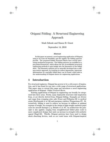
PRC-5003 Rev. Dceramic shot (57-63 HRC).3.1.2Shot Size and SelectionThe nominal size of shot (see appendix A) used on fillet surfaces shall not be greaterthan one-half the smallest fillet radius. It is preferred that a fillet radius of 0.031 inchesor greater be used when possible. Sharp corners should also be avoided and roundedwhen possible.Selection of shot size based on intensity is listed in Table 1.Table 1: Desired Minimum Shot Size for a Given IntensityIntensity0.012 A0.016 A0.020 A3.1.3Desired Minimum Size Peening MediaS-280 or CW-28 or Ceramic Bead Size 0.033S-390 or CW-41 or Ceramic Bead Size 0.046S-550 or CW-54IntensityIntensity can only be established during development by plotting a saturation curve,as shown in figure 1, and assuring that the required intensity (determined by the archeight of the test strip) falls on the right side of the knee of the curve. By doublingthe time of exposure, the arc height of a test strip should not increase by more than10%.Figure 1: Saturation Curve to Verify Peening IntensityVerify correct version before use.Page 6 of 14
PRC-5003 Rev. DFor initial process development, a saturation curve shall be generated for eachlocation where intensity is to be verified. A curve is produced by exposing individualtest strips for increasing time periods and plotting the results (exposure time vs. archeight). A minimum of four points other than zero shall be used to define the curve;one of the four points used to indicate saturation shall be at least double the time ofthe saturation point. Saturation is achieved when, as the exposure time for the teststrips is doubled, the arc height does not increase by more than 10%. The reuse oftest strips is not permitted.Except for sections less than 0.090 inches, a test strip “A” conforming to SAEJ442 utilizing procedure conforming to SAE J443 is typically used to determinearc height. The test strip “A” is used for arc heights between 0.004 and 0.024inches. For sections less than 0.090 inches, consult the cognizant materialand process (M & P) engineer.Table 2: Recommended Arc Height Intensity Based on ThicknessSteelUnder 200 ksi UTSOver 200 ksi UTS*Under 0.090 InchesThick0.090 – 0.375 Inches ThickDiscuss with M & PDiscuss with M & P0.008 – 0.012 A0.006 – 0.010 AOver 0.090 Inches Thick0.012 – 0.016 A0.006 – 0.010 A*For steel parts over 200 ksi tensile strength, use hard steel shot (55-65 HRC) or ceramicshot (57- 63 HRC).3.1.4 CoverageComplete visual coverage is a uniform and complete denting or obliterating of theoriginal surface of the part or work piece as determined by either of the followingmethods.Some vendors use a visual examination process using a 10X magnifying glassand other vendors use a liquid tracer system (typically fluorescent) using a10X inspection. The liquid tracer system uses a pre-shot peen coating andtypically fluorescent lighting to inspect post-shot peening.Typically 100% coverage (T Exposure Time in Figure 1) is specified; however,200% coverage (2T Exposure Time in Figure 1) is desired on low margin,fracture critical parts.3.1.5 Drawing Note Examples for Shot PeeningVerify correct version before use.Page 7 of 14
PRC-5003 Rev. DFor a steel under 200 ksi:SHOT PEEN PER SAE AMS 2430 WITH S-230 OR EQUIVALENT SIZESHOT PRIOR TO CHROMIUM PLATING. AN INTENSITY OF 0.008-0.012 AIS REQUIRED WITH 100% COVERAGE.For a steel over 200 ksi:SHOT PEEN PER SAE AMS 2430 WITH CERAMIC BEAD 0.024 BEAD SIZEPRIOR TO CHROMIUM PLATING. AN INTENSITY OF 0.006-0.010 A ISREQUIRED WITH 100% COVERAGE.3.2POST-PLATING HYDROGEN BAKEOUTIf the base material is a high strength ferrous alloy or case hardened, and has ahardness/temper or strength as defined in Table 1, a hydrogen bakeout shall berequired within four hours after the completion of the plating operation.Table 1: Steels That Require a Hydrogen Bakeout after Chromium PlateAlloysTypeHardness /TemperCarbon Steel, LowAlloy Steel, &MartensiticStainless Steels**Fasteners 36 HRCUltimateTensileStrength 160 ksiCarbon Steel, LowAlloy Steel, &MartensiticStainless Steels**All PartsOther ThanFasteners 40 HRC 180 ksiHigh StrengthPrecipitationHardening StainlessSteels***Case-hardened SteelParts***All PartsSee Tempers Listedin Table 1 Located inAMS 2759/9 150 ksiAll PartsSee Table 2 Locatedin AMS 2759/9 255 ksi inthe CaseMusic Wire, 52100,All PartsSee Table 2 Located 255 ksi440C, or Any Otherin AMS 2759/9Alloy Tempered Below375 F*****Require a post-plating hydrogen baking procedure of 375 F for 23 hours.Verify correct version before use.Page 8 of 14
PRC-5003 Rev. D*** Require a post-plating hydrogen baking procedure listed in AMS 2759/9. Anexample for an alloy steel with a hardness greater than 40 HRC:3.3WORK INSTRUCTIONSWork instructions shall be generated for implementing this process specification.The work instructions shall contain sufficient detail to ensure that themanufacturing process produces consistent, repeatable products that complywith this specification. For work performed at JSC facilities, these workprocedures consist of Detailed Process Instructions (DPIs). For contractedwork, the contractor shall be responsible for preparing and maintaining, andcertifying written work procedures that meet the requirements of thisspecification.A HYDROGEN BAKEOUT SHALL BE PERFORMED AT 375 F FOR 23 HOURS WITHIN4 HOURS AFTER THE COMPLETION OF THE PLATING OPERATION.4.0 REFERENCESThe following references were used in developing this process specification:ASTM B571Qualitative Adhesion Testing of MetallicCoatingsJPR 8500.4Engineering Drawing System RequirementsSAE AMS 2460Plating, ChromiumSAE AMS 2759/9Hydrogen Embrittlement Relief (Baking) of Steel PartsSAE AMS-S-13165AShot Peening of Metal PartsSAE AMS 2430Shot Peening, AutomaticSAE J442Test Strip, Holder, and Gage for Shot PeeningSAE J443Procedures for Using Standard ShotPeening Almen Test StripSAE J444Cast Shot and Grit Size Specifications forPeening and CleaningSOP-007.1Preparation and Revision of Process SpecificationsVerify correct version before use.Page 9 of 14
PRC-5003 Rev. D5.0MATERIALS REQUIREMENTSThe materials used shall meet the requirements of SAE AMS 2460.Prior to shot peening, parts shall be within dimensional and surface finish requirements.All heat treatment shall be completed before shot peening. All fillets shall be formed, allburrs shall be removed, and all sharp edges and corners to be peened shall be providedwith sufficient radii to result in complete coverage.Thin sections shall not distort after shot peening prior to plating.6.0PROCESS REQUIREMENTSAll electrodeposited chromium plating shall be applied according to thetechnical requirements of SAE AMS 2460. In addition to the control factors inSAE AMS 2460, these additional control factors are required: Organic contamination, metallic contamination and pH levels shall be checkedat the same time periods and the plating bath compositionProper bath temperature and temperature uniformity shall be checked andmaintainedComposition, organic contamination, metallic contamination and pH levelsshall be checked monthly (or more frequently)Tanks used for cleaning, pickling (or other activation methods) and rinsing are critical forproper surface preparation for plating. These tanks shall be controlled and maintainedfor proper chemistry, pH and low contamination levels using documented procedures.Fluoride levels often deplete in nitric/hydrofluoric pickling tanks over time and the typicaltitration test for “total acids” analysis is not adequate to check the nitric-to-hydrofluoricratio. Periodic removal of the old pickling solution, cleaning out the drained tank, andcreating a new pickling tank solution is often the easiest method to insure the propernitric-to- hydrofluoric ratio.In addition to the control factors in SAE AMS 2460, these additional controlfactors are required: Abrasive blasting media shall be removed prior to plating.The cleaning procedure shall not produce pitting or intergranular attack ofthe basis metal and shall preserve dimensional requirements.The plating shall be applied over a surface free from water breaks per AMS2460.Verify correct version before use.Page 10 of 14
PRC-5003 Rev. D7.0PROCESS QUALIFICATIONAdhesion tests, if required, shall meet the requirements of ASTM B571 bend test180 degrees with 4T mandrel to insure good plating deposit adhesion. Class 2plating that will be ground to final dimensions typically does not require an adhesiontest.Tribology and microhardness tests (ASTM E384) on test specimens may berequired to insure proper wear resistance.Periodic c
SAE AMS 2460 Plating, Chromium SAE AMS 2759/9 Hydrogen Embrittlement Relief (Baking) of Steel Parts SAE AMS-S-13165A Shot Peening of Metal Parts SAE AMS 2430 Shot Peening, Automatic SAE J442 Test Strip, Holder, and Gage for Shot Peening SAE J443 Procedures for Using Standard Shot Peening Almen Test Strip SAE J444 Cast Shot and Grit Size Specifications for Peening and Cleaning