Transcription
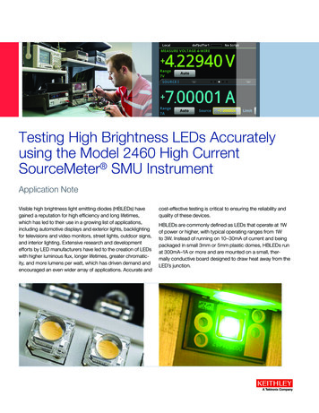
Testing High Brightness LEDs Accuratelyusing the Model 2460 High CurrentSourceMeter SMU InstrumentApplication NoteVisible high brightness light emitting diodes (HBLEDs) havegained a reputation for high efficiency and long lifetimes,which has led to their use in a growing list of applications,including automotive displays and exterior lights, backlightingfor televisions and video monitors, street lights, outdoor signs,and interior lighting. Extensive research and developmentefforts by LED manufacturers have led to the creation of LEDswith higher luminous flux, longer lifetimes, greater chromaticity, and more lumens per watt, which has driven demand andencouraged an even wider array of applications. Accurate andcost-effective testing is critical to ensuring the reliability andquality of these devices.HBLEDs are commonly defined as LEDs that operate at 1Wof power or higher, with typical operating ranges from 1Wto 3W. Instead of running on 10–30mA of current and beingpackaged in small 3mm or 5mm plastic domes, HBLEDs runat 300mA–1A or more and are mounted on a small, thermally conductive board designed to draw heat away from theLED’s junction.
Application NoteLED testing involves different types of test sequences at various stages of design research and development, on-wafermeasurements during production, and final tests of packagedparts. While concrete testing “recipes” often include a multitude of steps intended to verify product lifetime or extract dataon specific performance characteristics, they are beyond thescope of this application note. Rather, this application note isintended to provide solid information on the needed “ingredients” for these recipes—basic tests that illustrate how toprobe for the diodes’ characteristics and example test setups.This application note also illustrates how to use a Model 2460SourceMeter with the Keithley KickStart Software to create acurrent vs. voltage (I-V) sweep on an HBLED.Test DescriptionTesting LEDs typically involves both electrical and opticalmeasurements. This application note focuses on electricalcharacterization. Figure 1 illustrates the electrical I-V curveof a typical diode. A complete test includes a multitude ofvoltage values versus current operating points during the R&Dphase, but a limited sample of points is generally sufficient toprobe for the figures of merit, especially during the productvalidation phase and production.slope begins to level off as drive currents increase. The diodenormally operates in this region of relatively constant voltage.It is also quite useful to test the diode under these operating conditions. The forward voltage test (Vf ) is performed bysourcing a known current and measuring the resulting voltagedrop across the diode. Typical test currents range from tensof milliamps to amps, while the resulting voltage measurementis typically in the range of a few volts. The results of this testare typically used by engineers and designers, as the forwardvoltage is directly related to the chromaticity of the LED.Forward current biasing is also used for optical tests, becauseelectrical current flow is closely related to the amount of lightemitted. Optical power measurements can be made by placing a photodiode or integrating sphere close to the deviceunder test to capture the emitted photons. This light is thenconverted to a current, which can be measured by an ammeter or a SourceMeter instrument.In many test applications, the voltage and light output of thediode can be measured simultaneously using a fixed sourcecurrent value. In addition, details such as spectral outputcan be obtained by using the same drive current value and aspectrometer.Reverse Breakdown Voltage (VR)Figure 1. Typical HBLED DC I-V curve and test points (not to scale).Some tests require sourcing a known current and measuringa voltage, while others require sourcing a voltage and measuring the resulting current. A SourceMeter Source MeasureUnit (SMU) Instrument is ideal for these types of tests, because it can be configured to source voltages or currents andcan also measure each of these signal types.Forward Voltage Test (Vf ) and Optical TestsThe Vf test verifies the forward operating voltage of the visible LED. When a forward current is applied to the diode, itbegins to conduct. During the initial low current source values,the voltage drop across the diode increases rapidly, but the2www.tektronix.com/xxxApplying a negative bias current to the LED will allow probingfor the so-called Reverse Breakdown Voltage (VR). The testcurrent should be set to a level where the measured voltagevalue no longer increases significantly when the current is increased slightly more. At levels higher than this voltage, largeincreases in reverse bias current result in insignificant changes in reverse voltage. The specification for this parameter isusually a minimum value. The test is performed by sourcinga low-level reverse bias current for a specified time, thenmeasuring the voltage drop across the LED. The measurement result is typically in the range of tens of volts.Leakage Current (IL)Normally, moderate voltage levels (volts to tens of volts) areused to measure a Leakage Current (IL). The Leakage Current Test measures the low-level current that leaks across theLED when a reverse voltage less than breakdown is applied.It is a common practice for leakage measurements, and moregenerally for isolation measurements, to make sure only thata certain threshold is not exceeded, especially in production.There are two reasons for this. First, low current measurements require longer settling times, so they take longer tocomplete. Second, environmental interference and electricalnoise exert greater influence on low level signals, so extra
Testing High Brightness LEDs Accurately using the Model 2460 High Current SourceMeter SMU Instrumentcare in shielding is required. However, this extra shieldingmay complicate the test fixture and may interfere with automated handlers.Making Connections to the LEDThe LED is connected to the Model 2460 SourceMeter asshown in F igure 2. A four-wire connection is made to eliminate the effects of the lead resistance. When connecting theleads to the LED, the Force LO and Sense LO connectionsare made to the cathode terminal. The Force HI and Sense HIconnections are made to the anode. Make the connections asclose as possible to the cell to prevent the resistance of theLED’s terminals from affecting the measurement accuracy.Generating, Plotting, and Saving I-VSweeps Using the User Interface inThree Easy StepsModel 2460 SourceMeterForce HISense HIAFigure 4: Model 2460 SourceMeter 4-wire rear-panel connections to an LEDLEDVVSSense LOForce LOFigure 2: Model 2460 SourceMeter 4-wire connections to an LEDThe following figures show the physical connections for thefront and rear panels. Figure 3 shows the front-panel connections. You can make these connections with four insulatedbanana cables that are rated to the maximum current (7 A)such as two sets of the Keithley Instruments Model 8608High-Performance Clip Lead Set.The I-V sweep of an HBLED can be accomplished using theModel 2460 either from the front panel or over the bus. Just afew key strokes are needed to generate, graph, and save thedata to a USB drive. Here are the three easy steps to generate and graph a voltage sweep and then save the data to aUSB drive.Step 1. Creating and executing an I-V sweepfrom the front panel graphical user interfaceDescriptionKey StrokesReset instrument todefault stateMenu key Manage System ResetSet to source V and measure ISet to four-wire senseHome key Function key Source V Measure IMenu key Measure Settings Sense Mode 4-Wire SenseMenu key Source SweepConfigure sweep parameters Set desired Start, Stop, and Step V Scroll down and set Source Limit Press Generate to create sweepExecute I-V sweepHome key Trigger keyFigure 3: Model 2460 SourceMeter 4-wire front-panel connections to an LEDStep 2. Viewing the GraphFigure 4 shows the rear-panel connections. You can makethese connections with either the Model 2460-KIT ScrewTerminal Connector Kit (included with the Model 2460) or aModel 2460-BAN Banana Test Leads/Adapter Cable withappropriate cabling.To view the data graphically, press the MENU key and thenthe Graph button. The graph of the I-V sweep will automatically be displayed. To repeat the test, just press theTRIGGER key.www.tektronix.com/xxx3
Application NoteFigure 5 shows the I-V curve of an HBLED generated by theModel 2460. Figure 6 illustrates how bright an HBLED canget at the high levels of current.Figure 7. Saving data to a USB drive.Generating an I-V sweepusing KickStart SoftwareFigure 5. HBLED I-V sweep generated on the graph screen of the Model 2460.This example application uses Keithley KickStart StartupSoftware to generate a current-voltage sweep on a highbrightness LED. KickStart Instrument Control Software letsyou start taking measurements in minutes without complexinstrument programming. KickStart enables you to performI-V characterization, data acquisition and logging, and powersupply control on a variety of Keithley products. The softwareinterfaces to the instrumentation through any of the standardinterfaces: LAN, USB, and GPIB. Data can be displayed ingraphical, chart, or both formats. All data can be stored andexported for further analysis in a software environment suchas Microsoft Excel . Graphs can also be exported for installation in technical papers.In this example application, you will: Launch the KickStart software Create a new test project Select an instrumentFigure 6. HBLED illuminated at 4.1 volts and 4.8 amps Select a test typeStep 3. Saving the Data to a USB Drive Configure the test parametersTo save the I-V data to a USB drive, just insert a USB drive,press the MENU key, select Reading Buffers, and then pressSAVE TO USB (see Figure 7). Enter the name of the file. Thedata will be saved in a .csv format so it can later be downloaded to a spreadsheet and analyzed. Configure and view the graph screen Run the test View and save the test dataThe Model 2460 must be set to use the Test Script Processor (TSP ) command set before you can use the KickStartsoftware. By default, the Model 2460 is configured to use theSCPI command set.To enable TSP commands:1. Press the MENU key.2. Under System, select Settings.3. For Command Set, select TSP.4www.tektronix.com/xxx
Testing High Brightness LEDs Accurately using the Model 2460 High Current SourceMeter SMU Instrument4. At the prompt to reboot, select Yes.Launch KickStart and set up the testOnce the communication cable (GPIB, USB, or LAN) is connected to the computer and the TSP command set is enabled, you are ready to launch the KickStart software.To create a new test project:1. Launch the KickStart software. The Start Page is displayed, as shown in the following figure.Figure 8: KickStart Startup Software Start Page2. On the Start Page, click New KickStart Test (see Figure8). The Save As dialog box opens.3. Navigate to the location where you want to save your testprojects (you do not need to create a folder; KickStartdoes that for you). You can also use the default locationfor KickStart projects, which is C:\Users\My Documents\Keithley Instruments\KickStart.Figure 9: Select instrument by right-clicking on Model 2460:1 in the InstrumentConfiguration panel7. At the bottom of the screen, click Select Test Type. TheTest Types panel opens on the left side of the screen,showing the available test types (see Figure 10).4. Enter a name for the test and click Save. The test is savedas a .kst file in a folder with the name of the test project.5. Click Select Instrument in the bottom left corner of thescreen. If the Model 2460 is configured properly, it appears in the Instrument Configuration panel.6. Right-click Model 2460:1 and select Add Instrument(see Figure 9). Information about the connected Model2460 automatically appears in the bottom half of theInstrument Configuration panel.Figure 10: Selecting the test typewww.tektronix.com/xxx5
Application Note8. Right-click the I-V Characterizer test type and select AddTest Type. The Source Measure Settings window opens.(See Figure 11.)Advanced settingsParameterValueInput JacksFront or RearSensing Mode4-wireOutput OFF StateNormalHigh CapacitanceOffOffset CompensationOff11. To configure the graphing function, select the Graph tab.12. Click the button next to X-Axis and select Smu1.V(sweep voltage).13. Click the button next to Y-Axis and select Smu1.I (measure current).Figure 11: KickStart source and measure settings screenYou are now ready to run the test.9. Use the values in the following tables to specify the sourceand measure parameters for this example test (you canchange these values for your own application).Source settingsParameterValueSource ModeVoltage SweepSweep TypeLinearStart Voltage0Stop Voltage3.7Step Voltage0.05# Of StepsThis automatically populates based on the step voltagesetting. For this example, the value is 75.Current Limit6Delay Seconds0.01Run the test and view the graphTo run the test, select Start Test in the lower right cornerof the screen (see Figure 12). An I-V sweep is generatedautomatically and the results appear in real time on the graphscreen. The data on the graph is scaled automatically as thetest progresses.The following figure shows the result of running this exampleapplication.Measure settingsParameterValueCurrent MeasureEnabled, Auto RangeVoltage MeasureEnabled, Programmed Value10. In the lower part of the Measure Settings column, selectthe button next to Advanced Configuration and set theparameters listed in the following table.Figure 12: Results of running an I-V sweep on a high-brightness LEDTo save the graph as a .png file, click Graph Image in theExport Data/Graph area of the ribbon at the top of the screen.View and save the test data in tabular formYou can also view the results of the test in tabular form byselecting the Sheet tab. Figure 13 shows the test results onthe Sheet tab.6www.tektronix.com/xxx
Testing High Brightness LEDs Accurately using the Model 2460 High Current SourceMeter SMU InstrumentFigure 14. An HBLED’s junction heats as current is sourced through it. An HBLED’sforward voltage drops as its junction heats.Figure 13: Test data on the KickStart Sheet tabTo export the data as a .csv or .xls file, click Excel Format orCSV Format in the Export Data/Graph area of the ribbon atthe top of the screen.Typical Sources of ErrorJunction Self-HeatingWith increasing test times, the semiconductor junction of theLED will tend to heat. (See Figure 14.) The two tests susceptible to junction heating are the forward voltage and leakagecurrent tests. As the junction heats, the voltage will drop or,more importantly, the leakage current will increase during theconstant voltage test. Therefore, it is important to shorten thetest time as much as possible without sacrificing measurement accuracy or stability.The Model 2460 SourceMeter can configure the device soaktime before the measurement, as well as the amount of timethe input signal is acquired. The soak time allows any circuitcapacitance to settle before the measurement begins. Themeasurement integration time is determined by the numberof power line cycles (NPLC). If the input power were at 60Hz,a 1NPLC measurement would require 1/60th of a second or16.667ms. The integration time defines how long the analogto-digital converter (ADC) acquires the input signal, and itrepresents a trade-off between speed and accuracy.Typical polarization times for the Vf test are from less than afew hundred microseconds to five milliseconds, and from fiveto 20 milliseconds for the IL test. By using these short testtimes, errors due to the junction heating are reduced. Also,the junction heating characteristics can be determined byperforming a series of tests and only varying the test time.The 2460 can easily be programmed for this type of test, orthe equivalent of a pulsed I-V curve test. An example testscript is shown in Appendix A of this application note. Whenthe test is executed, the I-V curve in Figure 15 is displayedon the front panel of the instrument. Figure 16 shows the plotzoomed in so that you can see the short pulses and the verytight timing of the Model 2460.www.tektronix.com/xxx7
Application Notewith high resistance materials. Another way to reduce leakagecurrents is to use the built-in guard of the SourceMeter instrument. The guard is a low impedance point in the circuit thathas nearly the same potential as the high impedance point tobe guarded.Figure 15. Pulsed I-V test of the same HBLED previously tested and plotted inFigure 5.This concept is best illustrated by example (Figure 17). In thisexample, the LED to be measured is mounted on two insulated standoffs. Guarding is used in this circuit to ensure thatall the current flows through the diode and not through thestandoffs. In general, guarding should be used when sourcingor measuring currents less than 1μA. Connecting the Guardterminal of the instrument to the metal guard plate guards thiscircuit. This puts the bottom of the DUT insulator standoffs atalmost the same potential as the top. Both ends of the insulator are at nearly the same potential, so no significant currentcan flow through it. All the current will then flow through theLED as desired.InsulatorSourceMeterI-MeterHIIM ID ILDUTRL1V-SourceInsulatorIDIN/OUTRL2ILMetal Mounting PlateIN/OUTLOIM Measured currentID DUT currentIL Leakage currentA. UnguardedSourceMeterx1GUARDCable ShieldSafety ShieldInsulatorFigure 16. Pulsed I-V HBLED plot zoomed in to see the individual pulses.IDIM IDI-MeterLead ResistanceA common source of voltage measurement error is the seriesresistance from the test leads running from the instrument tothe LED. This series resistance is added into the measurement when making a two-wire connection. The effects of leadresistance are particularly detrimental when long connectingcables and high currents are used, because the voltage dropacross the lead resistance becomes significant compared tothe measured voltage.To eliminate this problem, use the four-wire remote sensingmethod, rather than the two-wire technique. With the four-wiremethod (see Figures 3 and 4), a current is forced through theLED using the Force HI/LO test leads, and the voltage acrossthe LED is measured using the Sense HI/LO set of leads. As aresult, only the voltage drop across the LED is measured.Leakage CurrentStray leakage in cables and fixtures can be a source of errorin measurements involving very low currents, such as for leakage currents. To minimize this problem, construct test fixturing8www.tektronix.com/xxxIN/OUTHI0V RL1V-SourceDUTMetal Mounting PlateIN/OUTLOB. GuardedConnect to earth safety groundusing #18 AWG wire or larger.Figure 17. Comparison of unguarded and guarded measurements.WARNING: Guard is at the same potential as Force HI.Therefore, if hazardous voltages are present at Force HI, theyare also present at the Guard terminal.Electrostatic InterferenceHigh resistance measurements can be affected by electrostatic interference, which occurs when an electrically chargedobject is brought near an uncharged object. To reduce theeffect of electrostatic fields, a shield can be built to enclosethe circuit being measured. As shown in Figure 17B, a metalshield connected to ground surrounds the LED under test.
Testing High Brightness LEDs Accurately using the Model 2460 High Current SourceMeter SMU InstrumentThe Force LO terminal of the SourceMeter instrument must beconnected to the metal shield to avoid noise due to commonmode and other interference. Using this type of shield will alsohelp shield operators from contacting the standoff metal plate,because the plate is at guard potential.Test System SafetyMany electrical test systems or instruments are capable ofmeasuring or sourcing hazardous voltage and power levels. Itis also possible, under single fault conditions (e.g., a programming error or an instrument failure), to output hazardous levelseven when the system indicates no hazard is present.These high voltage and power levels make it essential to protect operators from any of these hazards at all times. Protection methods include: Design test fixtures to prevent operator contact with anyhazardous circuit. Install High Brightness LEDs onto heat sinks to protect fromjunction heating, thermal failures and to ensure operationalreliability. Protect heat sink from hazardous voltages. Make sure the device under test is fully enclosed to protectthe operator from any flying debris. For example, capacitorsand semiconductor devices can explode if too much voltage or power is applied. Double insulate all electrical connections that an operatorcould touch. Double insulation ensures the operator is stillprotected, even if one insulation layer fails. Use high reliability, fail-safe interlock switches to disconnectpower sources when a test fixture cover is opened. Where possible, use automated handlers so operators donot require access to the inside of the test fixture or have aneed to open guards. Provide proper training to all users of the system so theyunderstand all potential hazards and know how to protectthemselves from injury. It is the responsibility of the testsystem designers, integrators, and installers to make sureoperator and maintenance personnel protection is in placeand effective. Specifications are subject to change without notice.ConclusionHBLEDs are advancing at an incredible pace. Researchers,LED design engineers, and manufacturers are working hard tomake them the lighting source choice of the future. In order toget there, LED developers and manufacturers must jump several hurdles, ever trying to reduce the cost of manufacturingLEDs while simultaneously trying to increase their efficiencyand light output. At the center of meeting these objectives,manufacturers require accurate, reliable, and repeatablesource and measurement equipment with the power and flexibility to adapt to their ever-changing testing needs.The Model 2460 High Current SourceMeter offers the featuresand flexibility to keep up with LED testing and developmentneeds of researchers and engineers. Innovative features likethe graphical user interface, real-time I-V curve plotting, andthe 7A, 100 watt analog capability allow the 2460 to makerepeatable measurements accurately, making it the perfectchoice for testing HBLEDs.www.tektronix.com/xxx9
Application NoteAppendix A: Pulsed HBLED I-V Test Script Code--[[This example program pulse sweeps a High Brightness LEDarguments:*bias: the offset voltage for the pulse sweep, between each step*start: The starting voltage for the sweep*stop: The stopping voltage for the sweep*points: The number of measurement points and number of steps in the sweep*Ton: the time on for each step voltage*Toff: the time at the bias level for each step*limit: the source current limit levelFor this example, we will start the voltage sweep at 1 volt, stop at 4 volts, 100 points,and an on time of 10 milliseconds and off time of 100 milliseconds.]]bias 0.0start 1.0stop 4.0points 100Ton 5e-3Toff 100e-3limit 4.0reset()--Config List c smu.FUNC DC VOLTAGEsmu.measure.func smu.FUNC DC CURRENTsmu.measure.nplc 0.01smu.measure.autozero.enable smu.OFF -- Need to turn off autozero for accurate timing.smu.measure.range limitsmu.measure.sense smu.SENSE 2WIRE-- Set the source range large enough to fit both the bias and level.-- This also turns off autoranging which will ruin our timing.smu.source.range math.max(math.abs(start), math.abs(stop), math.abs(bias))smu.source.delay 0smu.source.ilimit.level limitsmu.source.readback smu.OFF--Use start, stop and points parameters to calculate the step size.--Compute the measure delay time.stepsize (stop - start)/(points - 1)measuredelay Ton-((1/localnode.linefreq)*smu.measure.nplc 1e-3)--Set up levelList config list--Make ending point a little higher, so it will be included--(Problem with floating point respresentation of stepsize)stop stop 0.00000001for step start, stop, stepsize dodelay(0.001)smu.source.level .source.level bias10www.tektronix.com/xxx
Testing High Brightness LEDs Accurately using the Model 2460 High Current SourceMeter SMU Instrument--Save settings to biasList config list (only one imer t.stimulus trigger.EVENT NOTIFY1trigger.timer[1].start.generate trigger.OFFtrigger.timer[1].delay Tontrigger.timer[1].enable trigger.ON--Trigger model setuptrigger.model.setblock(1, trigger.BLOCK BUFFER CLEAR)trigger.model.setblock(2, trigger.BLOCK SOURCE OUTPUT, smu.ON)trigger.model.setblock(3, trigger.BLOCK CONFIG RECALL, "levelList")trigger.model.setblock(4, trigger.BLOCK NOTIFY, trigger.EVENT NOTIFY1)trigger.model.setblock(5, trigger.BLOCK BRANCH ONCE, 7)trigger.model.setblock(6, trigger.BLOCK CONFIG NEXT, "levelList")trigger.model.setblock(7, trigger.BLOCK MEASURE)trigger.model.setblock(8, trigger.BLOCK DELAY CONSTANT, measuredelay)trigger.model.setblock(9, trigger.BLOCK MEASURE)trigger.model.setblock(10, trigger.BLOCK WAIT, trigger.EVENT TIMER1)trigger.model.setblock(11, trigger.BLOCK CONFIG RECALL, "biasList")trigger.model.setblock(12, trigger.BLOCK MEASURE)trigger.model.setblock(13, trigger.BLOCK DELAY CONSTANT, Toff)trigger.model.setblock(14, trigger.BLOCK MEASURE)trigger.model.setblock(15, trigger.BLOCK BRANCH COUNTER, points, 4)trigger.model.setblock(16, trigger.BLOCK SOURCE OUTPUT, smu.OFF)display.changescreen(display.SCREEN GRAPH)--Start the trigger n(display.SCREEN GRAPH)www.tektronix.com/xxx11
Contact Tektronix:ASEAN / Australasia (65) 6356 3900Austria 00800 2255 4835Balkans, Israel, South Africa and other ISE Countries 41 52 675 3777Belgium 00800 2255 4835Brazil 55 (11) 3759 7627Canada 1 800 833 9200Central East Europe and the Baltics 41 52 675 3777Central Europe & Greece 41 52 675 3777Denmark 45 80 88 1401Finland 41 52 675 3777France 00800 2255 4835Germany 00800 2255 4835Hong Kong 400 820 5835India 000 800 650 1835Italy 00800 2255 4835Japan 81 (3) 6714 3010Luxembourg 41 52 675 3777Mexico, Central/South America & Caribbean 52 (55) 56 04 50 90Middle East, Asia, and North Africa 41 52 675 3777The Netherlands 00800 2255 4835Norway 800 16098People’s Republic of China 400 820 5835Poland 41 52 675 3777Portugal 80 08 12370Republic of Korea 001 800 8255 2835Russia & CIS 7 (495) 6647564South Africa 41 52 675 3777Spain 00800 2255 4835Sweden 00800 2255 4835Switzerland 00800 2255 4835Taiwan 886 (2) 2656 6688United Kingdom & Ireland 00800 2255 4835USA 1 800 833 9200Rev. 0415For Further InformationTektronix maintains a comprehensive, constantly expandingcollection of application notes, technical briefs and otherresources to help engineers working on the cutting edge oftechnology. Please visit www.tektronix.comCopyright 2015, Tektronix. All rights reserved. Tektronix products are coveredby U.S. and foreign patents, issued and pending. Information in this publicationsupersedes that in all previously published material. Specification and pricechange privileges reserved. TEKTRONIX and TEK are registered trademarksof Tektronix, Inc. All other trade names referenced are the service marks,trademarks or registered trademarks of their respective companies.06/151KW-60147-0
Visible high brightness light emitting diodes (HBLEDs) have gained a reputation for high efficiency and long lifetimes, which has led to their use in a growing list of applications,