Transcription
3DS.COM Dassault Systèmes Confidential Information 06/27/2017 ref.: Document Reference SolidPractices: Sheet MetalSOLIDWORKS StandardLast Update: 13 November 2019Revision 1.0
Table of Contents1)PREFACE . 52)BEST APPROACH TO MODELING SHEET METAL BODIES . 63)SHEET METAL ARCHITECTURAL CHANGES IN SOLIDWORKS 2013 . 74)VERIFICATION ON REBUILD . 85)CUT-EXTRUDE WITH NORMAL CUT OPTION . 96)ZERO GAP AND SELF-INTERSECTION . 117)AVOID SELF-INTERSECTION WITH EDGE-FLANGE . 128)DESIGNING SHEET METAL FROM THE FLAT. 139)BOUNDING BOX AND GRAIN DIRECTION . 1610)SHEET METAL MIRROR FEATURES . 1711)SWEPT FLANGE: TWO DIFFERENT FLAT PATTERN OPTIONS . 1812)LOFTED BEND “BENT” MANUFACTURING METHOD . 2013)LOFTED BEND “FORMED” MANUFACTURING METHOD . 22A)B)BEND LINES . 22APPLICATION OF LOFTED BEND LINES . 2314)FLAT PATTERN DRAWING VIEWS. 2415)SKETCHED BEND FEATURE AND BEND RELIEFS . 2516)IMPROVE FLAT PATTERN PERFORMANCE IN COMPLEX PARTS WITH FEATURE PATTERNS . 2717)ALTERNATIVE WAY OF THINKING ABOUT THE FLAT PATTERN . 2818)IMPORTANT SHEET METAL OPTIONS. 31A)B)C)19)A)B)C)D)THE MULTIBODY SHEET METAL OPTION . 31THE ‘SIMPLIFY BENDS’ OPTION . 31THE ‘MERGE FACES’ OPTION . 32BEND ALLOWANCE IN SOLIDWORKS . 33ROUND BENDS AND BEND ALLOWANCE . 33BEND ALLOWANCE CONTROL OPTION . 33FLATTEN LENGTH CALCULATION USING BEND DEDUCTION . 35BEND DEDUCTION FOR ANGLES LESS THAN 90 DEGREES BETWEEN FACES . 3720)SHEET METAL FORM TOOL . 3821)BEND TABLES . 41A)WHY TO USE BEND TABLES . 412
B)C)D)E)HOW TO USE SOLIDWORKS BEND TABLES . 41BEND TABLE AND BEND ANGLES OTHER THAN 90 DEGREES . 41RULES FOR BEND TABLES AND GAUGE TABLES . 42HANDLING BEND TABLE COMMON PROBLEMS . 4422)RECREATE TEMPLATES THAT PRODUCE OLD SHEET METAL ARCHITECTURE PARTS . 4723)NORMAL CUT WITH THE ’OPTIMIZE GEOMETRY’ OPTION . 4824)ALWAYS REMOVE “SELF-INTERSECTION” . 4925)FLATTENED MASS . 5026)CALCULATING THE K-FACTOR FOR SWEPT FLANGES . 5127)NORMAL CUT ‘OPTIMIZE GEOMETRY’ OPTION . 5228)TAB AND SLOT FEATURE IN ASSEMBLY COMPONENTS . 5329)ADD PUNCH TABLE TO DRAWING VIEWS OF DERIVED SHEET METAL PARTS . 5430)TURN ON OR TURN OFF OVERRIDE DEFAULT PARAMETERS . 5531)3 BEND CORNER RELIEFS . 5632)NORMAL CUT STANDALONE FEATURE. 5733)LINKING MATERIALS AND SHEET METAL PARAMETERS . 583
Revision HistoryRev #Date1.0Nov 2019DescriptionRevised for use by customers and reset as document version 1.0NoteAll SolidPractices are written as guidelines. You are recommended to use these documentsonly after properly evaluating your requirements. Distribution of this document is limited toDassault Systèmes SolidWorks employees, VARs and customers that are on activesubscription. This document may not be posted on blogs or any internal or external forumswithout prior written authorization from Dassault Systèmes SolidWorks Corporation.This document was updated using version SOLIDWORKS 2019 SP04. If you have questionsor need assistance in understanding the content, please get in touch with your designatedreseller.4
1) PrefaceThis SolidPractice document walks you through many situations that you can encounter whenusing the SOLIDWORKS Sheet Metal functionality.The document provides a general description of the most common sheet metal “problems”and misunderstandings, and compiles issues reported in over 3000 service requests fromsheet metal customers.Your Feedback RequestedWe would like to hear your feedback and also suggestions for new topics. After reviewingthis document, please take a few minutes to fill out a brief survey. Your feedback will help uscreate the content that directly addresses your challenges.5
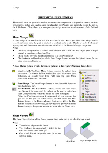
2) Best Approach To Modeling Sheet Metal BodiesSOLIDWORKS has specific sheet metal features that allow the creation of sheet metal bodiesvery quickly. However, in some circumstances, when the design demands certain types ofgeometries, the user has the option to use non-sheet metal feature tools and then use theInsert Bends or “Convert to Sheet Metal” features.When designing with sheet metal, it is important to think about the best approach to model ordesign a part. At times, it may appear quicker to use non-sheet metal features (boss-extrude,etc.), and then insert bends or convert to sheet metal. However, these options are problematicand the least flexible.When designing sheet metal parts, the order preference for use of feature tools are as follows:1. Use sheet metal features such as base-flanges, edge-flanges, miter flanges, etc.2. Use the Insert Bends feature.3. Use the Convert to Sheet Metal feature.When using the Insert Bends or Convert to Sheet Metal features, apply the features as earlyas possible during the part design phase. When possible, insert bends or convert to sheetmetal immediately after creating the first body feature.6
3) Sheet Metal Architectural Changes In SOLIDWORKS 2013Effective with the release of SOLIDWORKS version 2013, there is a revision to thearchitecture for the sheet metal functionality. With this release, the sheet metalFeatureManager design tree appears as follows:If you are using an older part template and the sheet metal FeatureManager tree does notlook like this, you must recreate your part template.7
4) Verification On RebuildActivating the Verification on rebuild option (Figure 4) and pressing Ctrl Q to forceregeneration of the model catches most feature problems immediately after creating a feature.As a best practice, force regenerate the model after creating each feature.Figure 48
5) Cut-Extrude with Normal Cut OptionIt is a recommendation to activate the Normal Cut option for most cut-extrude features thatyou apply to sheet metal bodies, even when this does not seem required needed. The onlytime that you must not use this option is when there is a specific reason for it. For example, ifthe material removed by a normal cut is more than expected, or if you need a specific bevelededge.In addition, whenever possible, create sheet metal holes by using the Cut-Extrude feature.This is because the Normal Cut option is not available for the Simple Hole feature and theHole Wizard feature.The next image (Figure 5) depicts a cut-extrude without the normal cut option. Notice thatapparently, the Normal Cut option is not required in this case. Inside the cutout, there is anedge-flange on both sides of the cut. Zooming in to one side of the edge flange (Figure 5a)reveals the appropriate reliefs. The edge flange on the other side (Figure 5b) does not havethe proper reliefs. Figure 5c shows the flat pattern for the part. Notice the irregular area at thecenter of the part.9
(Figure 5d) shows the same part. However, in this case, the normal cut option is active.Notice that the bend reliefs appear on both sides of the normal cut (Figure 5e & 5g). The flatpattern (Figure 5f) is now correct.10
6) Zero Gap and Self-IntersectionOne of the most common misunderstandings when working with sheet metal is the zero gapissue.A zero gap means that two faces "fuse" to each other (Figure 6 & 6a). This is whySOLIDWORKS displays the message “.the part self-intersects.” This message onlyappears if the Verification on rebuild option is active.The solution for this type of problem is to create a very small gap (0.001 mm) between thefaces. This separation is typically negligible for any sheet metal part, but not forSOLIDWORKS.Figure 6Figure 6a11
7) Avoid Self-Intersection with Edge-FlangeAs shown in (Figure 6a), one of the most typical situations for self-intersection is whenapplying an edge flange on a cut-extruded area. There are two basic approaches to avoid selfintersection. The first approach (Figure 7a) is to create a small gap at each side of the edgeflange.Figure 7aThe second approach takes advantage of the Offset option within the edge flangefunctionality. When active, this option automatically creates reliefs at the flange sides (Figure7b)Figure 7b12
8) Designing Sheet Metal From the FlatWhen designing sheet metal parts from the flat, it is important that every feature you createhave the proper reliefs, and that these reliefs belong to the feature you create. You must eithercreate the bend reliefs before the bend operation (that is, create the feature), or create thereliefs with the feature.For example, the following image (Figure 8) shows the part before applying an Edge-Flangefeature to that edge.Figure 8The next image (Figure 8a) shows the area after applying the Edge-Flange feature. Noticethat the area has an improper relief.Figure 8a13
(Figure 8b) shows the application of a manual relief by removing the “spiked” material usinga cut-extrude in a downstream feature. However, SOLIDWORKS is a feature-basedparametric modeler, which rebuilds from the top-down. Therefore, when the modelerrebuilds, because the Edge-Flange feature is above the Cut-Extrude feature, the userencounters a self-intersection problem.Figure 8bFigure 8c shows the proper way to handle this problem. The first solution is to avoid theproblem altogether, either by creating an Edge-Flange feature with the bend outside of theflange position (if possible), or by creating conditions for the edge flange that do not needreliefs.The other option is to use the automatic Edge-Flange reliefs (Figure 8c) and then use the cutextrude feature to remove the “spiked” piece.14
Figure 8c15
9) Bounding Box and Grain DirectionThe bounding box algorithm finds the smallest area in which to enclose the flat pattern forthe part. At times, the direction of the bounding box is not very effective (Figure 9). Whenthis occurs, you can specify the bounding box in any direction by using a sketch o
As a best practice, force regenerate the model after creating each feature. Figure 4 . 9 5) Cut-Extrude with Normal Cut Option It is a recommendation to activate the Normal Cut option for most cut-extrude features that you apply to sheet metal bodies, even when this does not seem required needed. The only time that you must not use this option is when there is a specific reason for it. For .