Transcription
EOMENGINEERING OPERATION& MAINTENANCEP4 ClampedPlastic PumpWhere Innovation FlowsWIL-10160-E-10
ContentsSection 1: Precautions - Read First!4Section 2: Wilden Pump Designation System5Section 3: How It Works —Pump & Air Distribution System6Section 4: Dimensional Drawings7P4 Pla st ic7Section 5: Performance8P4 Pla st ic R ubb er - F i tte d8P4 Pla st ic T PE - F it te d8P4 Pla st ic R edu ced - S tro k e PT F E - F i tte d9P4 Pla st ic F u ll - Str ok e PT F E - F itt ed.9Su ct ion - Li ft Cur ve s10Section 6: Suggested Installation, Operation,11Maintenance and TroubleshootingSection 7: Disassembly / Reassembly14Pu mp Di sa ss emb ly14Ai r Va lve / Ce nte r Se ct ion D isa ss emb ly17Rea ss emb ly H in ts & T i ps19PTF E Ga sk et K it In sta ll ati on20Section 8: Exploded View and Parts List21P4 Pla st ic F u ll - Str ok e, 3 - P iec e Cen ter - Se ct io n21P4 Pla st ic R edu ced Stro ke , 3 - P iec e Cen ter - Se ct io n23Section 9: Elastomer OptionsWIL-10160-E-10252Wilden
CopyrightCopyright 2018 PSG , a Dover Company. All rights reserved.PSG reserves the right to modify the information and illustrations in this document without prior notice. Theproduct described in this document is furnished under a license agreement or nondisclosure agreement. Nopart of this document may be reproduced, stored in a retrieval system, or transmitted in any form or anymeans electronic or mechanical, including photocopying and recording, without the written permission of PSG,a Dover Company, except as described by the terms of those agreements.This is a non-contractual document. 01-2019.TrademarksPSG and the PSG logo are registered trademarks of PSG. Wilden is a registered trademark of PSGCalifornia LLC. Pro-Flo SHIFT and Pro-Flo are registered trademarks of PSG California LLC. Wil-Flex is atrademark of PSG California LLC. Saniflex is a trademark of PSG California LLC.All trademarks, names, logos and service marks (collectively "trademarks") in this document are registeredand unregistered trademarks of their respective owners. Nothing contained in this document should beconstrued as granting any license or right to use any trademark without the prior written permission of thetrademark owner.WarrantyEach and every product manufactured by Wilden is built to meet the highest standards of quality. Every pumpis functionally tested to insure integrity of operation. Wilden warrants that pumps, accessories and partsmanufactured or supplied by it to be free from defects in material and workmanship for a period of five (5)years from date of installation or six (6) years from date of manufacture, whichever comes first.For more information, and to register your Wilden pump for warranty, please en
Section 1Precautions - Read First!CAUTION: Do not apply compressed air to the exhaust port— pump will not function.WARNING: Prevent static sparking — If staticsparking occurs, fire or explosion could result. Pump,valves, and containers must be grounded whenhandling flammable fluids and whenever discharge ofstatic electricity is a hazard. To ground the Wilden“Champ”, all clamp bands must be grounded to aproper grounding pointCAUTION: Do not over lubricate air supply — excesslubrication will reduce pump performance.TEMPERATURE LIMITS*:AcetalBuna-NGeolast NeopreneNordel EPDMNylonPFAPolypropylenePolyurethanePVDFSaniflex SIPD PTFE with EPDMbackedSIPD PTFE with NeoprenebackedPTFE1FKMWil-Flex –29 C to 82 C–12 C to 82 C–40 C to 82 C–18 C to 93 C–51 C to 138 C–18 C to 93 C–7 C to 107 C0 C to 79 C–12 C to 66 C–12 C to 107 C–29 C to 104 C4 C to 137 C–20 F to 180 F10 F to 180 F–40 F to 180 F0 F to 200 F–60 F to 280 F0 F to 200 F45 F to 225 F32 F to 175 F10 F to 150 F10 F to 225 F–20 F to 220 F40 F to 280 F4 C to 93 C40 F to 200 F4 C to 104 C–40 C to 177 C–40 C to 107 C40 F to 220 F–40 F to 350 F–40 F to 225 FCAUTION: Do not exceed 8 .6 bar (125 psig)air supply pressure.CAUTION: Before any maintenance or repair isattempted, the compressed air line to the pumpshould be disconnected and all air pressure allowedto bleed from pump. Disconnect all intake,discharge and air lines. Drain the pump by turning itupside down and allowing any fluid to flow into asuitable container.CAUTION: Blow out air line for 10 to 20 secondsbefore attaching to pump to make sure all pipelinedebris is clear. Use an in-line air filter.A 5µ (micron) air filter is recommended.NOTE: When installing PTFE diaphragms, it isimportant to tighten outer pistons simultaneously(turning in opposite directions) to ensure tight fit.1 4 Cto 149 C (40 F to 300 F) - 13 mm (1/2") and 25 mm (1")models only.NOTE: P4 PVDF and PFA pumps come standardNOTE: Not all materials are available for all models.Refer to Section 2 formaterial options for your pump.from the factory with expanded PTFE gasketsinstalled in the diaphragm bead of the liquidchamber, in the T-section and in the ball and seatarea. PTFE gaskets cannot be re-used.CAUTION: When choosing pump materials, be sure tocheck the temperature limits for all wetted components.Example: FKM has a maximum limit of 177 C (350 F) butpolypropylene has a maximum limit of only 79 C (175 F).NOTE: Before starting disassembly, mark a line fromeach liquid chamber to its corresponding airchamber. This line will assist in proper alignmentduring reassembly.CAUTION: Maximum temperature limits are based uponmechanical stress only. Certain chemicals will significantlyreduce maximum safe operating temperatures. Consultengineering guide for chemical compatibility and temperaturelimits.CAUTION: The P4 plastic pump is not submersible.CAUTION: Always wear safety glasses when operatingpump. If diaphragm rupture occurs, material being pumpedmay be forced out air exhaust.Plastic series pumps are made of virgin plastic and are notUV-stabilized. Direct sunlight for prolonged periods can causedeterioration of plastics.WIL-10160-E-10CAUTION: Pumps should be flushed thoroughly withwater before installation into process line.CAUTION: Tighten all hardware prior to installation.4Wilden
Section 2WILDEN PUMP DESIGNATION SYSTEMP4 PLASTICLEGENDP4/ X X X X X / XXX / XX / XMODEL25 mm (1") PumpMaximum Flow Rate:140 lpm (37 gpm)XX/XXXXO-RINGSVALVE SEAT SPECIALTY CODEVALVE BALLS(if applicable)DIAPHRAGMSAIR VALVEAIR CHAMBER OR CENTER SECTIONOUTER PISTONWETTED PATHMATERIAL CODESMODELP4 PRO-FLO WETTED PATHK PVDFP POLYPROPLYENEOUTER PISTONK PVDFP POLYPROPLYENEAIR CHAMBER/CENTER SECTIONA ALUMINUMC PTFE-COATED ALUMINUML ACETALS STAINLESS STEELV HALAR -COATEDALUMINUMAIR VALVEL ACETALP POLYPROPYLENESPECIALTY CODES0100010201030206DIAPHRAGMSBNS BUNA-N (Red Dot)BNU BUNA-N, ULTRA-FLEX (Red Dot)EPS EPDM (Blue Dot)EPU EPDM, ULTRA-FLEX (Blue Dot)FSS SANIFLEX [Hytrel (Cream)]NES NEOPRENE (Green Dot)NEU NEOPRENE, ULTRA-FLEX (Green Dot)PUS POLYURETHANE (Clear)TEU PTFE W/EPDMBACK-UP (White)TSS FULL-STROKE PTFEW/SANIFLEX BACKUPTSU PTFE W/SANIFLEX BACKUP (White)TWS FULL-STROKE PTFEW/WIL-FLEX BACKUPVTS FKM (White Dot)VTU FKM, ULTRA-FLEX WFS WIL-FLEX [Santoprene (Three Black Dots)]Wil-Gard II 110VWil-Gard II sensor wires ONLYWil-Gard II 220VPFA-coated hardware,Wil-Gard II sensor wires ONLY0502 PFA-coated hardware051305600561056305640603SS outer pistonsSplit manifoldSplit manifold, PFA-coated hardwareSplit manifold, discharge ONLYSplit manifold, inlet ONLYPFA-coated hardware, Wil-Gard II 110V06120504 DIN flange0506 DIN flange, PFA-coated hardware0512 Adapter block, no muffler,Pro-Flo ,center section06040606DIN flange, Wil-Gard II 220VDIN flange, PFA-coated hardware,Wil-Gard II 220VPFA-coated hardware, Wil-Gard II 220V066006610608061806220624VALVE BALLSBN BUNA-N (Red Dot)EP EPDM (Blue Dot)FS SANIFLEX [Hytrel (Cream)]FV SANITARY FKM(Two White Dots)NE NEOPRENE (Green Dot)PU POLYURETHANE (Brown)TF PTFE (White)VT FKM (White Dot)WF WIL-FLEX [Santoprene (Three Black Dots)]VALVE SEATSK PVDFP POLYPROPYLENET PFAVALVE SEAT O-RINGBN BUNA-NPU POLYURETHANE (Brown)TV PTFE ENCAP. FKMUltrapure, PFA-coated hardware,male connectionsUltrapure, PFA-coated hardware,Wil-Gard II 110V, male connectionsUltrapure, male connectionsUltrapure, Wil-Gard II 110V, maleconnectionsSplit manifold, Wil-Gard II 110VSplit manifold PFA-coated hardware,Wil-Gard II 110VNOTE: Most Elastomeric materials use colored dots for identification.NOTE: Not all models are available with all material options.Halar is a registered trademark of Solvay.Hytrel is a registered trademark of DuPont Dow Elastomers.WIL-10160-E-105Wilden
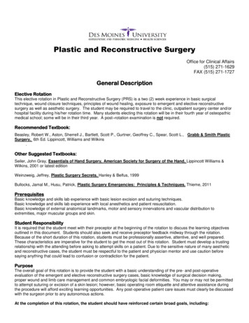
Section 3HOW IT WORKS — PUMPThe Wilden diaphragm pump is an air-operated, placement, self-priming pump. These drawings show the flow patternthrough the pump upon its initial stroke. It is assumed the pump has no fluid in it prior to its initial stroke.FIGURE 1 The air valve directs pressurizedair to the back side of diaphragm A. Thecompressed air is applied directly to theliquid column separated by elastomericdiaphragms. The diaphragm acts as aseparation membrane between thecompressed air and liquid, balancing theload and removing mechanical stress fromthe diaphragm. The compressed air movesthe diaphragm away from the center blockof the pump. The opposite diaphragm ispulled in by the shaft connected to thepressurized diaphragm. Diaphragm B is onits suction stroke; air behind the diaphragmhas been forced out to the atmospherethrough the exhaust port of the pump. Themovement of diaphragm B toward thecenter block of the pump creates a vacuumwithin chamber B. Atmospheric pressureforces fluid into the inlet manifold forcingthe inlet valve ball off its seat. Liquid is freeto move past the inlet valve ball and fill theliquid chamber (see shaded area).FIGURE 2 When the pressurizeddiaphragm, diaphragm A, reaches the limitof its discharge stroke, the air valveredirects pressurized air to the back side ofdiaphragm B. The pressurized air forcesdiaphragm B away from the center blockwhile pulling diaphragm A to the centerblock. Diaphragm B is now on its dischargestroke. Diaphragm B forces the inlet valveball onto its seat due to the hydraulic forcesdeveloped in the liquid chamber and manifold of the pump. These same hydraulicforces lift the discharge valve ball off itsseat, while the opposite discharge valveball is forced onto its seat, forcing fluid toflow through the pump discharge. Themovement of diaphragm A toward thecenter block of the pump creates a vacuumwithin liquid chamber A. Atmosphericpressure forces fluid into the inlet manifoldof the pump. The inlet valve ball is forcedoff its seat allowing the fluid being pumpedto fill the liquid chamber.FIGURE 3 At completion of the stroke,the air valve again redirects air to theback side of diaphragm A, which startsdiaphragm B on its exhaust stroke. As thepump reaches its original starting point,each diaphragm has gone through oneexhaust and one discharge stroke. Thisconstitutes one complete pumping cycle.The pump may take several cycles tocompletely prime depending on theconditions of the application.HOW IT WORKS — AIR DISTRIBUTION SYSTEMThe Pro-Flo patented air distribution system incorporates twomoving parts: the air valve spool and the pilot spool. The heartof the system is the air valve spool and air valve. This valvedesign incorporates an unbalanced spool. The smaller end ofthe spool is pressurized continuously, while the large end isalternately pressurized then exhausted to move the spool. Thespool directs pressurized air to one air chamber whileexhausting the other. The air causes the main shaft/diaphragmassembly to shift to one side — discharging liquid on that sideand pulling liquid in on the other side. When the shaft reachesthe end of its stroke, the inner piston actuates the pilot spool,which pressurizes and exhausts the large end of the air valvespool. The repositioning of the air valve spool routes the air tothe other air chamber.WIL-10160-E-106Wilden
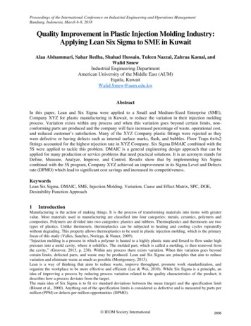
DIMENSIONAL DRAWINGP4 PlasticDIMENSIONSITEMABCDEFGHJKLMNPRSTRSTMETRIC (mm)STANDARD (inch)3947928746552812228730013728723618020310DIN FLANGE109 DIA.150 DIA.18 DIA.ANSI FLANGE99 DIA.127 DIA.20 0.44.3 DIA.5.9 DIA.0.7 DIA.3.9 DIA.5.0 DIA.0.8 DIA.LW0496 REV.AWIL-10160-E-107Wilden
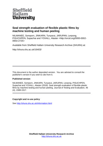
Section 5PERFORMANCEP4 PLASTICRUBBER-FITTEDShip Weight . Polypropylene 16.8 kg (37 lb)PVDF 21.3 kg (47 lb)Air Inlet . 13 mm (1/2")Inlet. . 38 mm (1-1/2")Outlet . 38 mm (1-1/2")Suction Lift . 4.88 m Dry (16')7.92 m Wet (26')Disp. Per Stroke1 . 1.19 L (0.314 gal)Max. Flow Rate . 348 lpm (92 gpm)Max. Size Solids . 4.8 mm (3/16")1Displacement per stroke was calculatedat 4.8 bar (70 psig) air inlet pressure againsta 2 bar (30 psig) head pressure.Example: To pump 159 lpm (40 gpm)against a discharge pressure head of2.7 bar (40 psig) requires 4.1 bar (60 psig)and 30.6 Nm3/h (18 scfm) air consumption.(See dot on chart.)Caution: Do not exceed 8.6 bar (125 psig)air supply pressure.Flow rates indicated on chart were determined by pumping water.For optimum life and performance, pumps should be specified so that dailyoperation parameters will fall in the center of the pump's performance curve.P4 PLASTICTPE-FITTEDShip Weight . Polypropylene 16.8 kg (37 lb)PVDF 21.3 kg (47 lb)Air Inlet . 13 mm (1/2")Inlet. . 38 mm (1-1/2")Outlet . 38 mm (1-1/2")Suction Lift . 3.96 m Dry (13')7.92 m Wet (26')Disp. Per Stroke1 . 1.18 L (0.311 gal)Max. Flow Rate . 354 lpm (94 gpm)Max. Size Solids . 4.8 mm (3/16")1Displacement per stroke was calculatedat 4.8 bar (70 psig) air inlet pres
WIL-10160-E-10 6 Wilden The Wilden diaphragm pump is an air-operated, placement, self-priming pump. These drawings show the flow pattern through the pump upon its initial stroke. It is assumed the pump has no fluid in it prior to its initial stroke. FIGURE 1 The air valve directs pressurized air to the back side of diaphragm A. The compressed air is applied directly to the liquid column .