Transcription
EOMENGINEERING OPERATION& MAINTENANCEP4 ClampedMetal PumpWhere Innovation FlowsWIL-10183-E-03
ContentsSection 1: Precautions - Read First!4Section 2: Wilden Pump Designation System5Section 3: How It Works6Section 4: Dimensional Drawings7Section 5: Performance8P4 Me tal R ubb er - F itt ed8P4 Me tal T P E- F i tte d8P4 Me tal R edu ce d Str oke PT F E - F itt ed9P4 Me tal F u ll S tro ke PT F E - F itt ed9P4 Me tal U ltr a - F l ex - F itt ed10Su ct ion - Li ft Cur ve s11Section 6: Suggested Installation, Operation,12Maintenance and TroubleshootingSection 7: Disassembly / Reassembly15Pu mp Di sa ss emb ly15Ai r Va lve / Ce nte r Se ct ion D isa ss emb ly18Rea ss emb ly H in ts & T i ps21Gas ke t Ki t I ns tal la tio n23Section 8: Exploded View and Parts List24P4 Me tal F u ll - S trok e Di ap hragm - F it ted24P4 Me tal R edu ce d - Stro ke Di aphr agm - F it ted26P4 Me tal San if lo 1 935 /2 004/ E C28Section 9: Elastomer OptionsWIL-10183-E-03302Wilden
CopyrightCopyright 2018 PSG , a Dover Company. All rights reserved.PSG reserves the right to modify the information and illustrations in this document without prior notice. Theproduct described in this document is furnished under a license agreement or nondisclosure agreement. Nopart of this document may be reproduced, stored in a retrieval system, or transmitted in any form or anymeans electronic or mechanical, including photocopying and recording, without the written permission of PSG,a Dover Company, except as described by the terms of those agreements.This is a non-contractual document. 01-2019.TrademarksPSG and the PSG logo are registered trademarks of PSG. Wilden is a registered trademark of PSGCalifornia LLC. Pro-Flo SHIFT and Pro-Flo are registered trademarks of PSG California LLC. Wil-Flex is atrademark of PSG California LLC. Saniflex is a trademark of PSG California LLC.All trademarks, names, logos and service marks (collectively "trademarks") in this document are registeredand unregistered trademarks of their respective owners. Nothing contained in this document should beconstrued as granting any license or right to use any trademark without the prior written permission of thetrademark owner.WarrantyEach and every product manufactured by Wilden is built to meet the highest standards of quality. Every pumpis functionally tested to insure integrity of operation. Wilden warrants that pumps, accessories and partsmanufactured or supplied by it to be free from defects in material and workmanship for a period of five (5)years from date of installation or six (6) years from date of manufacture, whichever comes first.For more information, and to register your Wilden pump for warranty, please en
Section 1Precautions - Read First!WARNING: Always wear safety glasses whenoperating a pump to avoid eye injury. If diaphragmrupture occurs, material being pumped maybe forcedout of the air exhaust.CAUTION: Do not exceed 82 C (180 F) airinlet temperature for all models.CAUTION: Thoroughly flush pumps before installingthem into process lines. Clean and/or sanitize FDAand USDA- approved pumps before using them.CAUTION: Do not apply compressed air to the exhaustport – pump will not function.CAUTION: Do not over-lubricate air supply– excess lubrication willreduce pump performance. Pump is pre-lubed.TEMPERATURE LIMITS:AcetalBuna-NGeolast NeopreneNordel EPDMNylonPFAPolypropylenePolyurethanePVDFSaniflex SIPD PTFE with EPDM-backedSIPD PTFE with Neoprene-backedPTFE1FKMWil-Flex 14 C–29 C to 82 C–12 C to 82 C–40 C to 82 C–18 C to 93 C–51 C to 138 C–18 C to 93 C–7 C to 107 C0 C to 79 C–12 C to 66 C–12 C to 107 C–29 C to 104 C4 C to 137 C4 C to 93 C4 C to 104 C–40 C to 177 C–40 C to 107 C–20 F to 180 F10 F to 180 F–40 F to 180 F0 F to 200 F–60 F to 280 F0 F to 200 F45 F to 225 F32 F to 175 F10 F to 150 F10 F to 225 F–20 F to 220 F40 F to 280 F40 F to 200 F40 F to 220 F–40 F to 350 F–40 F to 225 Fto 149 C (40 F to 300 F) - 13 mm (1/2") and 25 mm (1") models only.NOTE: Not all materials are available for all models. See "WildenPump Designation System on page 5 for material options for yourpump.CAUTION: Before attempting any maintenance or repair,disconnect the compressed air line to the pump and allow allair pressure to bleed from the pump. Disconnect all intake,discharge, and air lines. Drain the pump by turning it upsidedown and allowing any fluid to flow into a suitable container.Be aware of any hazardous effects of contact with yourprocess fluid.CAUTION: Before attaching the air line to the pump,blow out the air line for 10 to 20 seconds to make sureall pipeline debris is clear. Use an in-line air filter. A 5µ(micron) air filter is recommended.CAUTION: Pro-Flo pumps cannot be used insubmersible applications.CAUTION: Before installation, tighten all hardware.NOTE: Materials of construction and elastomer materialhave an effect on suction lift parameters. Please referto "Performance " on page 8 for specifics.NOTE: When installing PTFE diaphragms, it isimportant to tighten outer pistons simultaneously(turning in opposite directions) to ensure tight fit. (See"Maximum Torque Specifications" on page 21.)CAUTION: When choosing pump materials, be sure to check thetemperature limits for all wetted components.Example: FKM has a maximum limit of 177 C (350 F), butpolypropylene has a maximum limit of only 79 C (175 F).CAUTION: Maximum temperature limits are based on mechanicalstress only. Certain chemicals will reduce maximum safe operatingtemperatures significantly. Consult the Chemical Resistance Guidefor chemical compatibility and temperature limits.NOTE: Some PTFE-fitted pumps come standardfrom the factory with expanded PTFE gaskets installedin the diaphragm bead of the liquid chamber. PTFEgaskets cannot be re-used.NOTE: In the event of a power failure, close the shut-offvalve if you do not want the pump to restart when thepower returns.WARNING: Prevent Static Sparking. If static sparking occurs, fireor explosion could result. Pump, valves and containers must begrounded to a proper grounding point when handling flammablefluids and whenever discharge of static electricity is a hazard.CAUTION: All Wilden pumps are capable of passing solids. Use astrainer on the pump intake to ensure that the pump's rated solidscapacity is not exceeded.CAUTION: Do not exceed 8.6 bar (125 psig) air supply pressure.CAUTION: The process fluid and cleaning fluids must be compatiblechemically with all wetted pump components.WIL-10183-E-034Wilden
Section 2WILDEN PUMP DESIGNATION SYSTEMP4 METALLEGEND38 mm (1-1/2") PumpMaximum Flow Rate:348 lpm (92 gpm)P4/ X X X X X / XXX / XX / X XX /XXXXO-RINGSMODELVALVE SEATVALVE BALLSSPECIALTY CODEDIAPHRAGMS(if applicable)AIR VALVECENTER BLOCKAIR CHAMBERSOUTER PISTONWETTED PATHMATERIAL CODESMODELP4 PRO-FLO WETTED PATHA ALUMINUMS STAINLESS STEELW DUCTILE IRONOUTER PISTONA ALUMINUMS STAINLESS STEELM MILD STEELW DUCTILE IRONZ NO OUTER PISTONAIR CHAMBERS/CENTER SECTIONA ALUMINUMC PFA-COATEDL ACETAL (P4 only)N NICKEL-PLATEDS STAINLESS STEELV HALAR -COATEDCENTER SECTION/BLOCKL ACETALN NICKEL-PLATEDP POLYPROPYLENEAIR VALVEP POLYPROPYLENEL ACETALREFERENCES:1Meets Requirements of FDA CFR21.177Meets Requirements of USP Class VI3Meets Requirements of 1935/2004/EC2DIAPHRAGMSBNS BUNA-N (Red Dot)BNU BUNA-N, ULTRA-FLEXTM(Red Dot) 1,3EPS EPDM (Blue Dot)EPU EPDM, ULTRA-FLEXTM(Blue Dot) 1,3FBS SANITARY BUNA(Two Yellow Dots) 1,3FES SANITARY EPDM(Two Blue Dots) 1,3FSS SANIFLEX [Hytrel (Cream)] 1,3FWL FULL-STROKE SANITARYWIL-FLEX , IPD1[Santoprene (Two BlackDots)]FWS SANITARY WIL-FLEX ,EZ-INSTALL [Santoprene (Two Black Dots)] 1,3NES NEOPRENE (Green Dot)NEU NEOPRENE, ULTRA-FLEXTM(Green Dot)PUS POLYURETHANE (Clear)TEU PTFE w/EPDMBACKUP (White) 1,2,3TNU PTFE W/NEOPRENEBACKUP (White)TSS FULL-STROKE PTFEw/SANIFLEXTM BACK-UP 1,2,3TSU PTFE W/SANIFLEX BACKUP (White) 1,2,3TWS FULL-STROKE PTFEw/WIL-FLEXTM BACK-UP 1,2,3VTS FKM (White Dot)VTU FKM, ULTRA-FLEXTM(White Dot)WFS WIL-FLEXTM [Santoprene (Three Black Dots)]XBS CONDUCTIVE BUNA-N(Two Red Dots)VALVE BALLSBN BUNA-N (Red Dot)EP EPDM (Blue Dot)FS SANIFLEX [Hytrel (Cream)] 1,3NE NEOPRENE (Green Dot)PU POLYURETHANE (Clear)TF PTFE (White) 1,2,3VT FKM (Silver or White Dot)WF WIL-FLEX [Santoprene(Three Black Dots)]VALVE SEATSA ALUMINUMS STAINLESS STEELVALVE SEAT O-RINGSA ALUMINUMBN BUNA-N (Red Dot)FS SANIFLEX [Hytrel (Cream)] 1,3H ALLOY CM MILD STEELEP EPDM (Blue Dot)NE NEOPRENE (Green Dot)PU POLYURETHANE (Clear)S STAINLESS STEELVT FKM (Silver or White Dot)WF WIL-FLEX (Santoprene )VALVE SEAT O-RINGSTF PTFE 1,2,3SPECIALTY CODES0014 BSP 0023 Wing nuts0023 Wing nuts0030 Screen based0036 Screen based, BSP0044 Stallion, balls & seats ONLY0047 Stallion externals, balls and seats0067 Saniflo FDA, Wil-Gard 220V0070 Saniflo FDA0075 Saniflo FDA, Stallion balls and seats0079 Tri-clamp fittings, wing nuts0080 Tri-clamp fittings ONLY0100 Wil-Gard 110V0102 Wil-Gard sensor wires ONLY0103 Wil-Gard 220V0108 BSP, Wil-Gard 220V0118 Stallion balls and seats ONLY, BSP0120 Saniflo FDA, Wil-Gard 110V0330 Wing nuts BSPNOTE: Halar is a registered trademark of Solvay.NOTE: Hytrel is a registered trademark of DuPont Dow Elastomers.NOTE: Most elastomeric materials use colored dots for identification.NOTE: Not all models are available with all material options.WIL-10183-E-030067E Saniflo FDA, Wil-Gard II 220V (1935/2004/EC)0070E Saniflo FDA (1935/2004/EC)0075E Saniflo FDA, Stallion ballsand seats (1935/2004/EC)0120E Saniflo FDA, Wil-Gard II 110V (1935/2004/EC)5Wilden
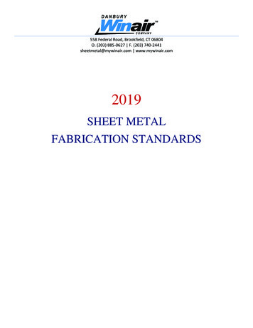
Section 3HOW IT WORKS — PUMPThe Wilden diaphragm pump is an air-operated, placement, self-priming pump. These drawings show the flow patternthrough the pump upon its initial stroke. It is assumed the pump has no fluid in it prior to its initial stroke.FIGURE 1 The air valve directs pressurizedair to the back side of diaphragm A. Thecompressed air is applied directly to theliquid column separated by elastomericdiaphragms. The diaphragm acts as aseparationmembrane between thecompressed air and liquid, balancing theload and removing mechanical stress fromthe diaphragm. The compressed air movesthe diaphragm away from the center blockof the pump. The opposite diaphragm ispulled in by the shaft connected to thepressurized diaphragm. Diaphragm B is onits suction stroke; air behind the diaphragmhas been forced out to the atmospherethrough the exhaust port of the pump. Themovement of diaphragm B toward thecenter block of the pump creates a vacuumwithin chamber B. Atmospheric pressureforces fluid into the inlet manifold forcingthe inlet valve ball off its seat. Liquid is freeto move past the inlet valve ball and fill theliquid chamber (see shaded area).FIGURE 2 When the pressurizeddiaphragm, diaphragm A, reaches the limitof its discharge stroke, the air valveredirects pressurized air to the back side ofdiaphragm B. The pressurized air forcesdiaphragm B away from the center blockwhile pulling diaphragm A to the centerblock. Diaphragm B is now on its dischargestroke. Diaphragm B forces the inlet valveball onto its seat due to the hydraulic forcesdeveloped in the liquid chamber and manifold of the pump. These same hydraulicforces lift the discharge valve ball off itsseat, while the opposite discharge valveball is forced onto its seat, forcing fluid toflow through the pump discharge. Themovement of diaphragm A toward thecenter block of the pump creates a vacuumwithin liquid chamber A. Atmosphericpressure forces fluid into the inlet manifoldof the pump. The inlet valve ball is forcedoff its seat allowing the fluid being pumpedto fill the liquid chamber.FIGURE 3 At completion of the stroke, theair valve again redirects air to the backside of diaphragm A, which startsdiaphragm B on its exhaust stroke. As thepump reaches its original starting point,each diaphragm has gone through oneexhaust and one discharge stroke. Thisconstitutes one complete pumping cycle.The pump may take several cycles tocompletely prime depending on theconditions of the application.HOW IT WORKS — AIR DISTRIBUTION SYSTEMThe Pro-Flo patented air distribution system incorporates twomoving parts: the air valve spool and the pilot spool. The heartof the system is the air valve spool and air valve. This valvedesign incorporates an unbalanced spool. The smaller end ofthe spool is pressurized continuously, while the large end isalternately pressurized then exhausted to move the spool. Thespool directs pressurized air to one air chamber whileexhausting the other. The air causes the main shaft/diaphragmassembly to shift to one side — discharging liquid on that sideand pulling liquid in on the other side. When the shaft reachesthe end of its stroke, the inner piston actuates the pilot spool,which pressurizes and exhausts the large end of the air valvespool. The repositioning of the air valve spool routes the air tothe other air chamber.WIL-10183-E-036Wilden
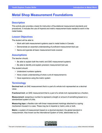
Section 4DIMENSIONAL DRAWINGP4 MetalDIMENSIONSITEMABCDEFGHJKLMNPRSTUVWMETRIC 93481391STANDARD 3.38.86.17.61.90.53.6LW0338 REV. AP4 Metal SanifloTM FDADIMENSIONSITEMMETRIC (mm)STANDARD 70.4LW0339 REV. AWIL-10183-E-037Wilden
Section 5PERFORMANCEP4 METALRUBBER-FITTEDShip Weight . Aluminum 13 kg (29 lb)316 Stainless Steel 20 kg (45 lb)Cast Iron 22 kg (49 lb)Alloy C 23 kg (51 lb)Air Inlet. 19 mm (3/4")Inlet. 38 mm (1-1/2")Outlet . 32 mm (1-1/4")Suction Lift .5.8 m Dry (19.0')8.0 m Wet (26.0')Disp. Per Stroke1 . 0.98 L (0.26 gal)Max. Flow Rate .
WILDEN PUMP DESIGNATION SYSTEM REFERENCES: 1 Meets Requirements of FDA CFR21.177 2 Meets Requirements of USP Class VI Meets Requirements of 1935/2004/EC. WIL-10183-E-03 6 Wilden The Wilden diaphragm pump is an air-operated, placement, self-priming pump. These drawings show the flow pattern through the pump upon its initial stroke. It is assumed the pump has