Transcription
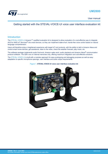
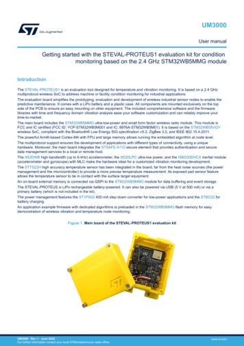
UM3000User manualGetting started with the STEVAL-PROTEUS1 evaluation kit for conditionmonitoring based on the 2.4 GHz STM32WB5MMG moduleIntroductionThe STEVAL-PROTEUS1 is an evaluation tool designed for temperature and vibration monitoring. It is based on a 2.4 GHzmultiprotocol wireless SoC to address machine or facility condition monitoring for industrial applications.The evaluation board simplifies the prototyping, evaluation and development of wireless industrial sensor nodes to enable thepredictive maintenance. It comes with a LiPo battery and a plastic case. All components are mounted exclusively on the topside of the PCB to ensure an easy mounting on other equipment. The included comprehensive software and the firmwarelibraries with time and frequency domain vibration analysis ease your software customization and can reliably improve yourtime-to-market.The main board includes the STM32WB5MMG ultra-low-power and small form factor wireless radio module. This module isFCC and IC certified (FCC ID: YCP-STM32WB5M001 and IC: 8976A-STM32WB5M01). It is based on the STM32WB55VGYwireless SoC, compliant with the Bluetooth Low Energy SIG specification v5.2, ZigBee 3.0, and IEEE 802.15.4-2011.The powerful Arm -based Cortex-M4 with FPU and large memory allows running the embedded algorithm at node level.The multiprotocol support ensures the development of applications with different types of connectivity, using a uniquehardware. Moreover, the main board integrates the STSAFE-A110 secure element that provides authentication and securedata management services to a local or remote host.The IIS3DWB high bandwidth (up to 6 kHz) accelerometer, the IIS2DLPC ultra-low power, and the ISM330DHCX inertial module(accelerometer and gyroscope) with MLC make the hardware ideal for a customized vibration monitoring development.The STTS22H high accuracy temperature sensor has been integrated in the board, far from the heat noise sources (the powermanagement and the microcontroller) to provide a more precise temperature measurement. Its exposed pad sensor featureallows the temperature sensor to be in contact with the surface target equipment.An on-board external memory is connected via QSPI to the STM32WB5MMG module for data buffering and event storage.The STEVAL-PROTEUS is LiPo rechargeable battery-powered. It can also be powered via USB (5 V at 500 mA) or via aprimary battery (which is not included in the kit).The power management features the ST1PS02 400 mA step down converter for low-power applications and the STBC02 forbattery charging.An application example firmware with dedicated algorithms is preloaded in the STM32WB5MMG flash memory for easydemonstration of wireless vibration and temperature node monitoring.Figure 1. Main board of the STEVAL-PROTEUS1 evaluation kitUM3000 - Rev 1 - June 2022For further information contact your local STMicroelectronics sales office.www.st.com
UM3000Overview1Overview1.1Precautions for use1.2Warning:Charge your device with a DC 5 V–500 mA USB charger at a temperature from 10 C to35 C.The kit must be used within the working temperature range. It must never be exposed toexcessive heat such as direct sunlight, fire, or heating equipment.Danger:Use only USB chargers equipped with short-circuit protections to prevent fire hazard.Danger:Use only the LiPo battery provided with the kit (HiMax 752535). A replacement of the batterywith an incorrect type can defeat a safeguard.LiPo batteries can be damaged and even explode if they are short-circuited or overchargeor with an improper usage, such as mechanical crushes, hot oven, or battery cutting.Warning:Pay attention to the sharp pins.Features Kit content: –the STEVAL-PROTEUS main board–LiPo battery 3.7 V, 480 mAh–Plastic case and screwsMain components on the STEVAL-PROTEUS:– 1.3RF specifications UM3000 - Rev 1STM32WB5MMG - ultra-low-power module, dual core 32-bit Arm Cortex-M4 MCU 64 MHz, CortexM0 32 MHz for real-time radio layer, with 1 Mbyte of flash memory, 256kbyte SRAM, and 2.4GHz RFsupporting Bluetooth Low Energy 5, 802.15.4, Zigbee 3.0, and Thread–IIS3DWB - ultra-wide bandwidth up to 6 kHz, low noise, 3-axis digital accelerometer–ISM330DHCX - iNEMO inertial module with machine learning core and finite state machine with digitaloutput–IIS2DLPC - high-performance ultra-low-power 3-axis digital accelerometer–STTS22H - low-voltage, ultra-low-power, 0.5 C accuracy I²C/SMBus 3.0 temperature sensor–2Gb QSPI NOR flash memory for data storage–STSAFE-A110 - secure element–STBC02 - Li-Ion linear battery charger with LDO–ST1PS02 - step-down converter with digital voltage selection–Three push-buttons (one reset, one user, one power-on battery)–Four LEDs (three user LEDs, one STBC02 LED status)–Flexible power supply options - LiPo battery, USB power, and primary battery–SWD connector for debugging and programming capability–34-pin expansion connector compliant with STMOD Temperature monitoring and vibration preprocessing data in the time and frequency domain, machinelearning, and AI to address industrial asset monitoringSTBLESensor app support for Android and iOS to ease the board and processing configuration, conditionmonitoring, and anomaly detectionComprehensive software libraries and demonstration examples availableRF output power up to 6 dBmpage 2/42
UM3000RF specifications UM3000 - Rev 1Operating band: 2400 MHz to 2480 MHzpage 3/42
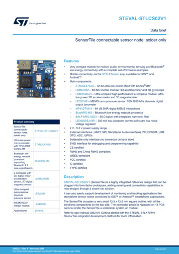
UM3000Package components1.4Package componentsThe STEVAL-PROTEUS1 evaluation kit package includes:1.a main board (dimensions: 29 mm x 35 mm)2.a LiPo battery 3.7 V 480 mAh (HiMax)3.a plastic case and some screwsFigure 2. STEVAL-PROTEUS1 package components1.5Ordering informationThe kit order code is STEVAL-PROTEUS1, which is identified with the finished good code ofSTEVAL PROTEUS1A. The main board included in the kit is the STEVAL-PROTEUS, which is identified withthe finished good code of STEVAL PROTEUSA.UM3000 - Rev 1page 4/42
UM3000Development environment2Development environment2.1System requirementsThe STEVAL-PROTEUS1 comes with a preloaded application firmware.To run the demo, you need: the STBLESensor app to be installed in your smartphone (Android or iOS)To develop your own project or customize the available one, you also need: 2.22.3a USB Type-A to Micro-B cablea Windows (version 7 or higher) PCthe STLINKV3-MINI for programming and debuggingDevelopment toolchains IAR Embedded Workbench for Arm (from V.8.50.9) Keil MDK-ARM (from V.5.32)STMicroelectronics STM32CubeIDE (from V1.9.0)Evaluation firmwareThe STEVAL-PROTEUS1 main board comes with an evaluation firmware preloaded in the STM32WB5MMGmicrocontroller.This firmware is a condition monitoring example based on Bluetooth Low Energy connectivity.The sensor node acts as BLE GATT server and can connect to a smartphone (based on Android or iOS) runningthe STBLESensor app that acts as a BLE GATT client.The STBLESensor app is used for board and processing configuration, sensor data, preprocessed vibration datamonitoring, and equipment status.You can download the latest version of this evaluation source code and the associated documentation fromwww.st.com.UM3000 - Rev 1page 5/42
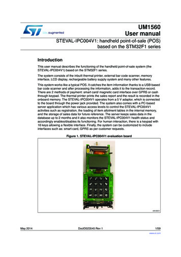
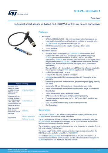
UM3000STEVAL-PROTEUS hardware architecture3STEVAL-PROTEUS hardware architectureThe STEVAL-PROTEUS is the main board of the kit. The whole system consists of the following functionalsubsystems: Power managementMicrocontroller and secure elementMEMS sensorsNOR flash memoryLEDs and push buttonsConnectorsThe sensors are connected to the microcontroller through SPI and I²C peripherals.The STSAFE-A110 is connected via I²C whereas the QSPI is used for the NOR flash memory.The external connectivity is allowed through: USB via USB connectorUART via SWD connectorUART, SPI, I²C, ADC, timer, SAI, and GPIOs routed on the 34-pin expansion connector (J9)Figure 3. STEVAL-PROTEUS: functional block diagramNOR Flash Memory2GbitST1PS02CQTRSTBC02AJRstep-down switchingregulatorLi-Ion linerarbattery chargerQUADSPIIIS3DWBSPI1STSAFE-110I2C2Secure Element34-pin connectorSPI2, I2C3USART, SAI,ADC, TIM,GPIOsISM330DHCXSTM32WB5MM6-Axis IMUDual Core ModuleUltra Low PowerCortex-M0 for real-time RadioCortex-M4F@64 MHzTemperatureSensorSTTS22HI2C1IIS2DLPCUltra Low powerAccelerometerUSB oduleUSBLC6-2SP6USB ESD protectionAs shown in the figure below, the STEVAL-PROTEUS comes with the following components: UM3000 - Rev 1U1 - STM32WB5MMG ultra-low-power and small form factor certified 2.4 GHz wireless module that embedsboth Arm Cortex -M4 and Arm Cortex -M0 .U2 - STBC02U3 - ST1PS02page 6/42
UM3000STEVAL-PROTEUS hardware architecture U4 - STG4160U5 - IIS3DWBU6 - ISM330DHCXU7 - STTS22HU8 - IIS2DLPCU9 - STSAFE-A110U10 - STG3692Three push buttons (reset, power, and user)Three application LEDsOne LED for the STBC02 statusLiPo battery connectorPrimary battery connectorSTDC14 connectorUSB Micro-B receptacleHigh-current connector for board-to-FPC/board-to-board (0.4 mm pitch), 34-pin connectorFigure 4. STEVAL-PROTEUS components: top viewUM3000 - Rev 1page 7/42
UM3000STEVAL-PROTEUS hardware architectureNo component is placed on the STEVAL-PROTEUS bottom side to make the surface smooth, so that it canperfectly adhere to the equipment to monitor. This is a key feature of vibration monitoring.Figure 5. STEVAL-PROTEUS bottom viewUM3000 - Rev 1page 8/42
UM3000Power management3.1Power managementThe STEVAL-PROTEUS power management block is based on the DC-DC step-down switching regulator(STP1S02) and on a linear battery charger (STBC02) to charge the LiPo battery and to switch automaticallythe power path between the LiPo battery and the USB source.The DC-DC step-down converter has two different power paths: VOUT1 and VOUT2. The subsystem connectedto the VOUT2 can be enabled or disabled by acting on the STP1S02 according to the application needs.Figure 6. STEVAL-PROTEUS: power management systemThe main board can be powered via: the USB Micro-B plug connector (5 VDC/500 mA) through the J2 USB micro-B receptaclethe LiPo rechargeable battery (3.7 VDC/480 mAh) through the J3 connectorthe primary battery (3 VDC 3.6 VDC), which is not included in the kit, through the J4 connectorThe power section includes: U2 - STBC02 Li-Ion linear battery chargerU3 - ST1PS02 400 mA step-down switching regulatorD3 - USBLC6-2 low capacitance ESD protection for USBJ2 - USB Micro-B receptacleJ3 - LiPo battery connectorJ4 - primary battery connectorJ5 - main voltage selectorS2 - power buttonD5 - STBC02 status LEDTable 1. Power supply setupUM3000 - Rev 1Supply sourceInput connectorConfigurationLiPo batteryJ3J5 1-2 jumper fittedUSBJ2J5 1-2 jumper fittedPrimary batteryJ4J5 2-3 jumper fittedpage 9/42
UM3000Microcontroller3.2MicrocontrollerThe STEVAL-PROTEUS embeds an STM32WB5MMG, which is an ultra-low-power and small form factor certified2.4 GHz wireless module. It supports Bluetooth Low Energy 5.2, Zigbee 3.0, OpenThread, dynamic and staticconcurrent modes, and 802.15.4 proprietary protocols.Based on STMicroelectronics STM32WB55VGY wireless microcontroller that embeds both Arm Cortex -M4and Arm Cortex -M0 , the STM32WB5MMG provides the best-in-class RF performance thanks to its goodreceiver sensitivity and a high output power signal. Its low-power features enable an extended battery lifetime,small coin-cell batteries, or energy harvesting.The STM32WB5MMG requires no RF expertise and is the best way to speed up any development and to reducethe associated costs. The module is completely protocol stack royalty-free.Figure 7. STM32WB55xx block diagramUM3000 - Rev 1page 10/42
UM3000Secure element3.3Secure elementThe STEVAL-PROTEUS comes with an STSAFE-A110, which acts as a secure element that providesauthentication and secure data management services to a local or remote host. It consists of a full turnkeysolution with a secure operating system that runs on the latest generation of secure microcontrollers.The STSAFE-A110 can be integrated in: 3.4IoT (Internet of things) devicessmart-home, smart-city, and industrial applicationsconsumer electronics devices, consumables, and accessoriesMEMSThe STEVAL-PROTEUS embeds some MEMS sensors for vibration and temperature monitoring, preprocessing,and analysis. The sensor data are analyzed through the algorithms that run on the STM32WB5MMGmicrocontroller.The board mounts the following sensors: 3.4.1IIS3DWB - ultra-wide bandwidth, low-noise, 3-axis digital vibration sensor (U5)ISM330DHCX - 3-axis accelerometer and 3-axis gyroscope with embedded machine learning core (U6)IIS2DLPC - high-performance, ultra-low-power 3-axis accelerometer (U8)STTS22H - low-voltage, ultra-low-power, temperature sensor (U7)IIS3DWBThe IIS3DWB is a system-in package that features a 3-axis digital vibration sensor with low noise over anultra-wide and flat frequency range.The wide bandwidth, low noise, very stable, repeatable sensitivity, and the capability of operating over anextended temperature range (up to 105 C) make the device particularly suitable for vibration monitoring inindustrial applications.The high performance delivered at low power consumption, the digital output, and the embedded digital features,such as FIFO and the interrupts, enable features for battery-operated industrial wireless sensor nodes.The IIS3DWB has a selectable full-scale acceleration range of 2/ 4/ 8/ 16 g and is capable of measuringaccelerations with a bandwidth up to 6 kHz with an output data rate of 26.7 kHz.The device integrates a 3 kB first-in, first-out (FIFO) buffer to avoid any data loss and to limit intervention of thehost processor.The ST MEMS sensor module family leverages the robust and mature manufacturing processes already used forthe production of micromachined accelerometers and gyroscopes to serve automotive, industrial, and consumermarkets. The sensing elements are manufactured using the ST proprietary micromachining process, whereas theembedded IC interfaces are developed using CMOS technology.The IIS3DWB has a self-test capability, which allows checking whether the sensor is correctly working in the finalapplication.The IIS3DWB is available in a 14-lead plastic land grid array (LGA) package and is guaranteed to operate over anextended temperature range from -40 C to 105 C.Table 2. IIS3DWB I/O configurationUM3000 - Rev 1I/OConfigurationPI1SPI2 CLKPI3SPI2 MOSIPD3SPI2 MISOPF12SPI CSPF15INT1-INT2page 11/42
UM3000MEMS3.4.2ISM330DHCXThe ISM330DHCX is a system-in-package that features a high-performance 3D digital accelerometer and a 3Ddigital gyroscope tailored for Industry 4.0 applications.The various sensing elements are manufactured using specialized micromachining processes, while the ICinterfaces are developed using CMOS technology that allows the design of a dedicated circuit, which is trimmedto match the characteristics of the sensing element.In the ISM330DHCX the sensing elements of the accelerometer and of the gyroscope are implemented on thesame silicon die, guaranteeing superior stability and robustness.The ISM330DHCX has a full-scale acceleration range of 2/ 4/ 8/ 16 g and a wide angular rate range of 125/ 250/ 500/ 1000/ 2000/ 4000 dps that enables its usage in a broad range of applications.All the design aspects and the calibration of the ISM330DHCX have been optimized to reach superior accuracy,stability, extremely low noise, and full data synchronization. The embedded features (Machine Learning Core,programmable FSM, FIFO, sensor hub, event decoding, and interrupts) enable smart and complex sensor nodes,which deliver high performance at very low power.The ISM330DHCX is available in a 14-lead plastic land grid array (LGA) package.Table 3. ISM330DHCX I/O configuration3.4.3I/OConfigurationPI1SPI2 CLKPI3SPI2 MOSIPD3SPI2 MISOPH15SPI CSPB8INT1PF4INT2IIS2DLPCThe IIS2DLPC is a three-axis linear accelerometer with digital I²C/SPI output interface.It has full scales of 2g/ 4g/ 8g/ 16g selectable by the user and can measure accelerations with output datarates from 1.6 Hz to 1600 Hz.The IIS2DLPC has a high-performance mode and four low-power modes, which can be changed on-the-fly,providing outstanding versatility and adaptability to the requirements of the application.The accelerometer has an integrated 32-level first-in, first-out (FIFO) buffer that allows the user to store data inorder to limit intervention by the host processor. The embedded self-test capability allows checking whether thesensor is correctly working in the final application.The IIS2DLPC has a dedicated internal engine to process motion and acceleration detection, including free-fall,wake-up, highly configurable single/double-tap recognition, activity/inactivity, stationary/motion detection, portrait/landscape detection, and 6D/4D orientation.The IIS2DLPC is available in a small thin plastic land grid array package (LGA) and it is guaranteed to operateover an extended temperature range from -40 C to 85 C.Table 4. IIS2DLPC I/O configurationUM3000 - Rev 1I/OConfigurationPI1SPI2 CLKPI3SPI2 MOSIPD3SPI2 MISOPH6SPI CSPF1INT1PF2INT2page 12/42
UM3000MEMS3.4.4STTS22HThe STTS22H is an ultra-low-power, high accuracy, digital temperature sensor that offers a high performanceover the entire operating temperature range.The STTS22H band-gap temperature sensor is coupled with an A/D converter, signal processing logic, and anI²C/SMBus 3.0 interface, all in a single ASIC.This sensor is housed in a small 2 x 2 x 0.50 mm 6-lead UDFN package with the exposed pad down for a bettertemperature match with the surrounding environment.The STTS22H is factory calibrated and requires no additional calibration efforts on the customer side.The STEVAL-PROTEUS1 embeds this high accuracy temperature sensor, which is placed in the board corner,far from the heat noise sources (power management and microcontroller) for a more precise temperaturemeasurement.The exposed pad sensor features maximize the thermal coupling between the evaluation board and the targetequipment.Figure 8. STEVAL-PROTEUS1: temperature sensorUM3000 - Rev 1page 13/42
UM3000NOR flash memory3.5NOR flash memoryThe STEVAL-PROTEUS comes with a 2Gb serial NOR flash memory, MX66L2G45GXRI00, able to store up to256 MB.The MX66L2G45G uses a Macronix proprietary memory cell, which reliably stores memory contents even after100,000 program and erase cycles.The communication between the MCU and the memory takes place via the QSPI bus.Figure 9. MX66L2G45G block diagram3.63.6.1ConnectorsSWD and UART connectorsThe STEVAL-PROTEUS features an STDC14 connector to program the microcontroller via a dedicated flat cableconnected to the STLINK-V3MINI.Tx and Rx pins for the UART communication are also routed on this connector.UM3000 - Rev 1page 14/42
UM3000ConnectorsFigure 10. STDC14 connector3.6.2USB connectorThe Micro-B USB connector (J2) can be used to power the board, recharge the battery when the battery isinserted, or for data transfer once connected to a PC.UM3000 - Rev 1page 15/42
UM3000Connectors3.6.3Battery connectorsThe STEVAL-PROTEUS provides two connectors to insert the battery: the J3 connector for the LiPo battery included in the kitthe J4 connector for a primary battery, which is not included in the kitFigure 11. LiPo battery connector3.6.434-pin expansion connectorA high current connector for board-to-FPC/board-to-board (0.4 mm pitch) 34-pin connector is mounted on theSTEVAL-PROTEUS to add a further sensor or a different connectivity.The pinout of the 34-pin connector is compliant with the STMOD by using a dedicated adapter (not included inthe kit).Figure 12. Mapping of the 34-pin connector resourcesUM3000 - Rev 1page 16/42
UM3000LEDs and push buttons3.7LEDs and push buttonsThe STEVAL-PROTEUS mounts four LEDs: D1 - green LED for applicationD2 - red LED for applicationD8 - blue LED for applicationD5 - orange LED for battery charger statusThe board also mounts three push buttons: S1 - MCU reset buttonS2 - power push buttonS3 - user push buttonFigure 13. STEVAL-PROTEUS1: LEDs and push buttonsNote:UM3000 - Rev 1When the STEVAL-PROTEUS is powered exclusively by the LiPo battery, the S2 push button is used to switchthe system on (hardware event) and off (software event).To switch the system on, push and hold the S2 button for at least three seconds: the orange LED turns on thenoff.To switch the system off, push and hold the S2 button until the orange LED turns on. A command is sent to thebattery charger to put it in shipping mode (low-power mode).page 17/42
UM3000How to use the STEVAL-PROTEUS14How to use the STEVAL-PROTEUS14.1How to assemble the kitThe STEVAL-PROTEUS1 kit includes a plastic case with its related screws to host the board and the LiPo battery,allowing an easy fixing for demo purposes only.To assemble the kit, follow the procedure below.Step 1.Fix the main board to the case bottom (A) with the four screws included in the kit.Pay attention to the board orientation.Step 2.Put the LiPo battery in the top case (B) and insert the battery cable into the dedicated hole.Figure 14. Kit assemblyUM3000 - Rev 1Step 3.Put the cover on the battery and close it using two screws.Step 4.Plug the LiPo battery connector to the J3 connector.page 18/42
UM3000How to assemble the kitStep 5.Close the A and B case parts using four screws.Figure 15. Fixing the screwsStep 6.Use something thin (for example, a needle) to access the holes and press the push buttons.Figure 16. Push button pressersUM3000 - Rev 1page 19/42
UM3000How to supply power to the STEVAL-PROTEUS board4.2How to supply power to the STEVAL-PROTEUS boardIt is recommended to power the board with the included LiPo battery (3.7 V, 480 mAh) or the USB. In any case,set the jumpers as follows: J10 openJ5 short 1-2There are different power supply options for the board: USB onlyFigure 17. 5 V USB supply voltage LiPo battery only (press the PWR button (S2) for at least 2s to power up)Figure 18. LiPo battery supplyUM3000 - Rev 1page 20/42
UM3000How to supply power to the STEVAL-PROTEUS board USB and LiPoFigure 19. Battery charging and USB supply voltageIf the USB cable and the LiPo battery are plugged, the STBC02 charges only the battery.A primary battery (3 V or 3.6 V), not included in the kit, can be used to power the STEVAL-PROTEUS. In thiscase, change the power path by placing a shunt on the 2-3 pins of J5 and connect the battery to J4 mates with665002113322 (housing) and 665165128130 (precrimped wire).When LiPo battery-powered, the equipment is intended to work properly with an operating temperature range of10-35 C.Without the battery, the equipment is intended to work properly with an operating temperature range of 10-45 C.Caution:When using a primary battery, check that the operating temperature range is compatible with 10-45 C.Pay attention to the configuration of J5 and J10 jumpers.4.2.1Power on-off procedureIf the system board is not powered via the LiPo battery, the board turns on and off when you connect anddisconnect an external supply, respectively. Otherwise: for power-on, push and hold the S2 button for at least three seconds: the orange LED turns on then off; The power-on is managed by the STBC02 battery charger wake-up feature.for power-off, push and hold the S2 button until the orange LED turns on.Note:The STEVAL-PROTEUS embeds the STBC02 device with shipping mode features used to switch off the system.Thus, in the application code examples provided with the software, the microcontroller detects the push actionand sends the shipping mode command to the STBC02 to force the device to shutdown mode (low-power mode).Caution:UM3000 - Rev 1Do not disconnect the LiPo battery from the board connector while the board is still powered to avoid putting theSTBC02 in a protection mode. Normal operation can be restored by reconnecting the battery and supplying theUSB input voltage.page 21/42
UM3000How to program the STEVAL-PROTEUS4.3How to program the STEVAL-PROTEUSStep 1.Note:Step 2.Connect the STEVAL-PROTEUS board to an STLINK-V3MINI programmer using a 14-pin flat cable.The programmer and the cable are not included in the STEVAL-PROTEUS1 kit.Connect the board and the programmer to a PC/laptop using Micro-USB cables.Figure 20. STEVAL-PROTEUS and STLINK-V3MINI connectionStep 3.Once the STEVAL-PROTEUS has been connected to a PC, launch your preferred IDE forprogramming and debugging or the STM32CubeProgrammer to update the firmware.Step 4.If you choose the STM32CubeProgrammer, select [ST-LINK] on the right top corner of the screen andpress connect.Figure 21. STM32CubeProgrammer: connectionUM3000 - Rev 1page 22/42
UM3000How to program the STEVAL-PROTEUSStep 5.Choose [Open file] and select the new .bin or .hex file to be flashed on the board.Figure 22. STM32CubeProgrammer: file openingStep 6.Click on [Download] to flash the board.Figure 23. STM32CubeProgrammer: board flashingUM3000 - Rev 1page 23/42
UM3000How to run the demonstration firmware4.4How to run the demonstration firmwareThe STEVAL-PROTEUS1 kit includes a preloaded application example, which is compatible with theSTBLESensor mobile application for Android and iOS.To run the condition monitoring demonstration firmware, follow the procedure below.UM3000 - Rev 1Step 1.Check the position of the jumpers on the main board (J5 1-2 fitted, J10 open).Step 2.Power up the system through the LiPo battery or the USB.Step 3.Press the S2 power for three seconds.Step 4.Install and launch the STBLESensor app on your smartphone and click on [Connect to a device].Step 5.Look for the [Proteus device] on the app device list and push it to connect.Step 6.Surf the mobile app pages to retrieve temperature sensor data, MEMS sensor plotting, and FFTplotting.In the predictive maintenance tab, time and frequency domain vibration analysis can be visualized withthe status coming from set thresholds. Fast firmware upgrade over-the-air is available in a dedicatedtab.page 24/42
Schematic diagramsFigure 24. STEVAL-PROTEUS circuit schematic (1 of 5)J1QUADSPI CLKSPI ISM330DHCX CSSPI1 SCKSPI1 MISOI2C3 SCLSPDT SEL 1VDD MCUSPDT SEL 2USART1 RXUSB DMUSB DPSWDIOSWCLKSPI IIS3DWB CSLPUART1 RXST1PS02 VOUTVDD MCUR14.7kVDD MCUR24.7kR34.7kN.MR44.7kN.MI2C1 SCLI2C3 SCLI2C1 SDAI2C3 SDALED GREENR5300RD1LED GREENCCD8LED 12PB13PB14PB15R70RN.MD2LED RED595885ANT INANT NC10NRSTRF OUT616213AAAR24523RLED 6922232440LPUART1 RXLPUART1 TXSPI2 MISOsGPIO 3 / SAI1 SD A / ADC1 IN4BATMS ADCPRIMBATMS ADCIIS3DWB INT2ISM330DHCX INT2IIS2DLPC INT2ST1PS02 D0ST1PS02 D1ST1PS02 D2IIS2DLPC INT1 / SYS WKUP3RESET33346870738081677574778266656376SPI2 NSSSPI2 SCKLED GREENSPI2 MISOpSPI2 MOSIpQUADSPI BK1 IO1QUADSPI BK1 IO2QUADSPI BK1 IO3LED REDST1PS02 PGOODMX66L2G45G nRSTSTSAFE nRESETSTBC02 CENST1PS02 AUXPRIMBATMS CTRLPWM / TIM1 CH2C6100nF3C283pFISM330DHCX INT1GPIO 2 / SAI1 FS A / SPI2 NSSsC303pFC293pFBATMS ADCC313pFC323pFCon2 Strp male SMDBOOT0J10VDD MCUC31uFC44.7uFD3USB DM21S3C35100nFPush-Bottom WE434331013822D9ESDALC6V1-1U2V USBC5100nF12R810k1Push-Bottom BUTTON USER2PRIMBATMS ADCIIS3DWB TCLED BLUEINT / I2C3 SMBAUSART1 RTSUSART1 CTSSPI1 MOSIUSART1 TXI2C1 SDAI2C1 SCLQUADSPI BK1 IO0GPIO 1 / SAI1 SCK A / SPI2 SCKsQUADSPI BK1 NCSGPIO 2 / SAI1 FS A / SPI2 NSSsBUTTON USERI2C3 SDASPI2 MOSIsVDD A14PA15PH0PH1PH3-BOOT0STLINK-V3 Adapter ReceptacleMates with SS 5VSS 31VSS 57VSS 60VSS 84VSS 86U1ADC / ADC1 IN5STTS22H INT / I2C1 SMBA53157608486NRSTLPUART1 TXC253pFQUADSPI BK1 NCS7964787242SWDIOSWCLKGPIO 1 / SAI1 SCK A / SPI2 SCKsSTBC02 WAKE-UPLED BLUEBOOT0NRSTISM330DHCX INT1IIS3DWB INT1GPIO 4 / SAI1 MCLK A / TIM1 CH2NSTBC02 SW SELSTBC02 CHGPE0PE1PE2PE3PE42468101214VREF VDDAVBATVSSSMPSVDDSMPSVDDUSB13579111312VDD MCU4615161732UM3000 - Rev 15USB DP3I/O1-1I/O1-6GNDVBUSI/O2-3I/O2-4USBLC6-2P66USB D-54USB D C24100nF434This kit features a specific STM32 device version, which allows the operation of any bundled commercial stack/library available.This STM32 device shows a "U" marking option at the end of the standard part number and is not available for sales.To use the same commercial stack in his/her application, a developer may need to purchase a part number specific to this stack/library.The price of those part numbers includes the stack/library royalties.UM3000Schematic diagramspage 25/42
UM3000 - Rev 1Figure 25. STEVAL-PROTEUS circuit schematic (2 of 5)ST1PS02 VOUTVDD MEMORYM1A2A3B1B5C1C3C5D1D5E1E2E3E4E5VDD IO3CSA4B2MX66L2G45G nRSTQUADSPI CLKD3QUADSPI BK1 IO0D2QUADSPI BK1 IO1C4QUADSPI BK1 IO2D4QUADSPI BK1 IO3C2QUADSPI BK1 NCSDNUVCCGNDMX66L2G45GXRI00UM3000Schematic diagramspage 26/42
J3321VCCDD IDGND6789V USBSTBC02 NTCSTBC02 SYSC5D5Li-Ion Battery ReceptacleV USB or V BAT450 mA x2M1M2M3M4V PRIMBATTC810uFF3E4E3C91uFE2F2F1USB2.0 MICROI FAST 200 mAPrimary Battery ReceptacleJumper-Femalemates with 665002113322(housing) and665165128130(pre-crimped wire)STBC02 SYSJ5C331uF12V MAINA4D4R121KI PRE 10 mAJ4J14STBC02 YS2SW1 ISW1 OASW1 OBC1SW SELBATMSNTCISETIPRESTBC02 SW SELC4STBC02 BATMSD1STBC02 NTCA5B5BAT1BAT2R140RV BATSTBC02 BATMSD2WAKE-UPC114.7uF3STBC02 WAKE-UPMain Voltage SelectorThe pin has aninternal 50 kOhmpull-downresistorV PRIMBATTV PRIMBATTPRIMBATMS CTRLU41234PRIMBATMS ADCR2339k4.25 V - 2.50 VR2127kS1GND1GNDDSELS2VCCVLV MAIN2ST1PS02 D0PGOODVINSWST1PS02 D110ST1PS02 D211D0GNDD1VOUT2AUXCLD227L135122.2uH 1.5A1ST1PS02 VOUT2210uH346181S2Push-Bottom WE434331013822L21ST1PS02 AUX4D6ESDALC6V1-1U2STBC02 WAKE-UPL322.2uH 1.5AST1PS
1.4 Package components. The STEVAL-PROTEUS1 evaluation kit package includes: 1. a main board (dimensions: 29 mm x 35 mm) 2. a LiPo battery 3.7 V 480 mAh (HiMax) 3. a plastic case and some screws Figure 2. STEVAL-PROTEUS1 package components. 1.5 Ordering information. The kit order code is STEVAL-PROTEUS1, which is identified with the finished .