Transcription
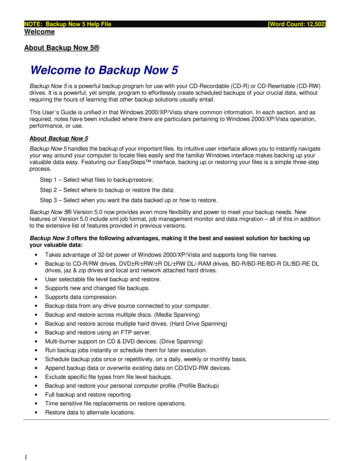
UM2800User manualGetting started with the STEVAL-VOICE-UI voice user interface evaluation kitIntroductionThe STEVAL-VOICE-UI Amazon qualified evaluation kit is designed to allow evaluation of a cost-effective way to integrateAVS for AWS IoT Services into smart devices, so they can implement state-of-art, hands-free voice control based on naturallanguage comprehension.Users will therefore enjoy a heightened experience with target IoT end products, with the ability to talk to Amazon Alexa andcontrol smart home devices, get assistance, listen to the news, check the weather forecast, play music, etc.The software package implements audio front-end, Amazon wake word, audio playback and Amazon Alexa communicationprotocol software. The SDK runs on internal memories only, offering maximum integration and cost-effective solutions.The STEVAL-VOICE-UI is built with a modular approach for easy prototyping and debugging purposes as well as easyadaptation to specific microphone spacings, user interface and audio output requirements.Figure 1. STEVAL-VOICE-UI voice user interface evaluation kitUM2800 - Rev 3 - June 2021For further information contact your local STMicroelectronics sales office.www.st.com
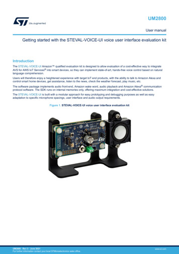
UM2800Overview1OverviewThe STEVAL-VOICE-UI kit features: STM32H753VIT6E high-performance MCU with 2 MB embedded Flash, 1 Mb embedded SRAM and incost-effective LQFP package 2.4 GHz Wi-Fi subsystem with Murata 1DX module used in bypass mode coupled to ISSI IS25LP016D 2MBytes NOR Flash memory 3 x MP23DB01HP MEMS microphones with 36 and 30 mm spacing FDA903D class D digital input automotive audio amplifier 8 Ohm loudspeaker 4 RGB LEDs and 4 simple LEDs Joystick, reset and user push buttons High modularity with mother/daughter board Small 36x65 mm² footprint with simple and cost-effective PCB design1.1Kit componentsThe STEVAL-VOICE-UI kit package includes: STEVAL-VUIMB02V1: VUI mother board embedding the STM32H753VIT6E MCU and the Wi-Fi module STEVAL-VUIDB01V1: VUI daughter board including the audio front-end (MP23DB01HP microphones andFDA903D audio amplifier) and the user interface (buttons, joystick, LEDs and USB) 8 Ohm speaker Mechanical parts STLINK-V3MINI debugger/programmer for STM32 with programming cable USB A to C connector cable1.2Functional block diagramFigure 2. STEVAL-VOICE-UI functional block diagramSTEVAL-VUIMB02V1STEVAL-VUIDB01V1Digital microphoneMP23DB01HPCortex-M7F@480MHz1MB RAM2MB Flash40pin I2Sconn PDM(CN1) I2CI2CST1S12GR700mA DC-DC(Optional)STDC14PDMSTM32H753VIT6EI2SAudio putconnector4x RGBLEDLED1202Led driverSPIWi-Fi sub-systemWi-Fi Module(bypass mode)Murata 1DXUM2800 - Rev 32MB NORFlash2x ButtonsJoystickUSB-C4 LEDISSI IS25LP016Dpage 2/35
UM2800System requirements1.3System requirementsWindows OS (7, 8 and 10), Linux 64-bit, or MacOS html5 web browser versionCompanion app requires Android 7 or iOS 14 1.4Development toolchainsIAR Systems - IAR Embedded Workbench EWARM 1.5Power supplyThe easiest way to power the STEVAL-VOICE-UI kit is via the USB-C connector.Table 1. Power supply optionsJ1J8DescriptionCLOSECLOSESingle power supply from USB. Do not connect V PA (J2)CLOSEOPENSingle power supply from V PA (J2) up to 5 VOPENCLOSEDual power supply:OPENOPEN 5 V from USB V PA from J2 Up to 18 V5 V from external source (CN1)Figure 3. STEVAL-VOICE-UI power supply block J25VU43V3STM32H7ST1S12V PAJ1MP23DB01HPFDA903DAudio AmplifierUM2800 - Rev 3LED1202STSAFEWi-Fi sub-module2MB NORMurata 1DXpage 3/35
UM2800User interfaces1.6User interfacesFigure 4. STEVAL-VOICE-UI user interfacesUM2800 - Rev 31.4 LEDs2.Reset button3.4 RGB LEDs4.J85.J16.Loudspeaker terminals7.Programming connector (STDC14)8.User button9.Joystickpage 4/35
UM2800Demo firmware2Demo firmware2.1Pre-requisitesThe pre-installed ST VOICE UI flashed demo firmware demonstrates a voice service solution able to connect toAVS for AWS IoT.A direct Internet connection is needed (without proxy).As an Alexa device, you need a regular Amazon account to connect to AVS for AWS IoT service.The account can be created on www.amazon.com or other local versions.The users who have registered to Amazon Music service will be able to play music on the device.2.2Device setupStep 1.Power the device through a USB C cable.Step 2.Configure the network connection.Step 3.Register to AVS for AWS IoT service.Step 2 and 3 can be performed using a smartphone application (Section 2.2.1 ) or the embedded http console(Section 2.2.2 ), as described in the following chapters.2.2.1Android and iOS usersstvs Smart Config is a smart phone application that allows configuring the device and the demos.It also manages localization. The application is available on both Google Play and Apple stores.UM2800 - Rev 3page 5/35
UM2800Device setupStep 1.To configure a new device, push the [Onboarding new device] button and follow the instructions.Figure 5. stvsSmartConfig procedure2.2.2Other users - HTTP UIThe device embeds an HTTP service that the consumer can connect to via smartphone or PC and an HTML5browser (Safari or Chrome). To connect to the server, the smartphone must be connected to the same Wi-Fi spotof the board.The HTTP UI interface tab allows checking the service status and changing some configurations.Two cases must be distinguished:1.Wi-Fi connection2.Other connections (Wi-Fi information already logged in)2.2.2.1Wi-Fi connection2.2.2.1.1Wi-Fi configurationBy default, the device comes in Wi-Fi AP mode and offers a hotspot whose name looks like stvs-xxxx.Step 1.Ensure the device is in Access Point (AP) mode.Step 1a. Check the current mode using the RGB LEDs (see Table 2).Step 1b. If not in AP mode, refer to Section 2.8 .Step 2.UM2800 - Rev 3Connect your PC or smartphone to the hotspot and then connect the browser to the address192.168.0.1.page 6/35
UM2800Device setupStep 3.Go to STVS UI [Setup] tab.Figure 6. STVS user interface2.2.2.2Step 4.Push the [Wi-Fi-Scan] button.All visible Wi-Fi hotspots will be listed in the scan results.Step 5.Scroll down and select your home network (in this case the hotspot is called [Netbook]).Step 6.Scroll back and type the Wi-Fi password.Step 7.Scroll down and select the connection type ([Wi-Fi STA].Step 8.To connect the board, scroll up and select [Re-connect].Step 9.Check RGB LEDs on the board (see Table 2).After few seconds, the Wi-Fi state should switch from “disconnected” to “connected “.The board reboots and connects to the network via Wi-Fi using a new IP address.Connection to Wi-Fi STAIn this case, hotspot Wi-Fi information has already been configured and the board is properly connected to it(refer to Section 2.2.2.1.1 , step 6).UM2800 - Rev 3page 7/35
UM2800Device setupNote:Step 1.Get the board IP address available in the serial console.Step 2.Refer to Section 2.10 to access the traces.Traces with the IP address looks like:00:00:00 :192.168.X.X:06:STVS EVT NETWORK IP(0x3001D5BC)The IP is no longer in the AP mode (address 192.168.0.1).2.2.3UM2800 - Rev 3Step 3.Connect to the UI using the given address.Step 4.If there is no serial console connected to the board, scan the network using a free application.Once installed, the application shows all STVS devices available in the neighborhood and allowsconnecting to them:–iPhone users can install “Bonjour HTTP search” from the App Store;–Android users can download “BonjourBrowser” from the Android Store;–PC users can install “bonjour browser” from www.tildesoft.com.Device registrationStep 1.If not yet connected to the http console, go to Section 2.2.2.2 .Step 2.Under [Setup] tab, click [Registration](HTML5 browser required).The browser will display a code and a link (amazon.com/code).page 8/35
UM2800Device setupStep 3.Copy the code and click on the link.Figure 7. CBL device registration codeYou will be redirected to an Amazon sign-in page.Figure 8. Amazon sign-in pageStep 4.Enter you Amazon credentials.If credentials are correct, you will be redirected to the following page.Figure 9. Register device pageUM2800 - Rev 3page 9/35
UM2800Privacy modeStep 5.Paste or enter the code given in the previous page and click on continue.If this step is successful, the board connects to AVS for AWS IoT and the LEDs turn off after fewseconds.Figure 10. Successful registrationNow you can test the device. You can talk to Alexa (for example, asking: “Alexa, what time is it ?”)2.3Privacy modeThe device enters privacy mode when you briefly push the white user button.A red LED switches on and the device does not send any other audio request to the cloud, even when saying"Alexa".2.4AlarmsWhen an alarm or a timer is set and the device rings, you have to press the joystick to acknowledge and stop thealert.Example of voice requests: “Alexa set a timer for 2 minutes”; “Alexa set an alarm at 5 pm”; “Alexa set alarm” Alexa will ask for details.2.5Amazon music controlIf the Amazon account used to register the board is registered to Amazon music, it is possible to ask Alexa to playsome songs or playlists and navigate it.The joystick is also used to navigate music playlists.2.6LED UI animationsTable 2. RGB LED animations indicating device stateEffectsUM2800 - Rev 3ColorInternal service IDAnimationCommentBlueRestartingSolidJust after the reset.It remains like thisuntil the first event isdispatched.Blue/CyanBootingNormal beatIt remains like thisduring the basicsystem initialization.page 10/35
UM2800LED UI animationsEffectsColorCyan/OrangeBlue/YellowUM2800 - Rev 3Internal service IDconfiguration changeshas ipAnimationCommentNormal beatIt signals aconfiguration state,mainly when theboard is in AccessPoint mode.Very fast blinkingDuring the boot, itsignals by a sortevent that the networkhas an IP address.Red/Purpleerror need credentialsFast blinkingIt signals an error,the system needsAWS and AVScredentials. It shouldoccur only duringtest and developmentconfiguration.Green/Rederror need registrationSlow rotationIt signals an error.The system needs anAVS registration (referto Section 2.2.3 ).Yellow/GreenconnectingFast counterclockwise rotationIt signals areconnection to theAVS for AWS IoTservice.RedPrivacyVery long pulsationIt signals the privacymode is ON.Blue/BlackWakeupVery fast rotationShort signal when aWakeup occurs.BlackIdleAll offIt signals the board isready for interactions.BlueactiveListeningVery long pulsationThe AVS for AWS IoTservice is listening forutterance.BlackstopListeningAll offNot signalled yet.BlackstartListeningAll offNot signalled yet.CyanactiveSpeakingVery very long pulsationThe AVS for AWS IoTservice is speaking orplaying.BlackstopSpeakingAll offNot signalled yet.BlackstartSpeakingAll offNot signalled yet.BlackthinkingAll offNot signalled yet.Red/BlackalertingSlow counterclockwise rotationA timer/alarm/notification/rememberis triggered.GreenblinkGreenSlow blinkingIt signals ageneral purposeevent (Debug).page 11/35
UM2800Buttons and joystickEffectsColorInternal service IDCommentRedblinkRedSlow blinkingIt signals ageneral purposeevent (Debug).YellownotificationVery long pulsationIt signals anotification.PurpledndVery long pulsationIt notifies a do notdisturb.Very fast rotationIt signals theuser has madea long push (seeSection 2.8 andSection 2.9 ).SwitchNetwork (6sec)White2.7AnimationFactoryReset (10sec)Buttons and joystickThe STEVAL-VOICE-UI has two push buttons and one joystick.The black (reset) push button reboots the board, whereas the white (user) button is for mute/privacy state.A long white button push is used to change the board network configuration (see Section 2.8 and Section 2.9 ).Table 3. User buttonClick typeShort clickLong clickModeReferencePrivacy modeSee Section 2.3 .1 bip or voice: Switch networkSee Section 2.8 .2 bips or voice: Factory ResetSee Section 2.9 .The joystick is mapped to control play and stop. This mapping is arbitrary and is customizable by the user.Table 4. Joystick default ghtDownVolume downUpVolume upNetwork switchingIf the device keeps trying to connect to the Wi-Fi and the fast white circular sequence on RGB LEDs occurs or ifyou want to connect to Ethernet, you have to re-enter or modify Wi-Fi credentials and the device has to be in APmode.In such cases, follow the below procedure to switch to another network.Step 1.Note:Do not push for 10 seconds to avoid starting the sequence described in Section 2.9 .Step 2.UM2800 - Rev 3Push the white user button for about 6 seconds.A circular RGB LED sequence occurs while the button is pushed (see Section 2.6 ).After 6 seconds, check the log traces to know what mode you switched to (refer to Section 2.10 ).If the device does not switch to the desired network, repeat the procedure starting from step 1.page 12/35
UM2800Factory reset2.92.10Factory resetStep 1.Push the white user button for about 10 seconds.A first circular sequence on RGB LEDs occurs for 6 seconds, indicating the Wi-Fi configuration isswitching back to AP mode.Then, a second sequence starts for 4 seconds more.Step 2.Release the button.The device reboots with factory default settings.Log traces and STLINK-V3MINI connectionStep 1.Connect the provided STLINK-V3MINI between the board and a PC to get some debugging traces.Step 2.Connect with any serial terminal such as Tera Term, for instance.The UART configuration is:–Baud rate 921600–Data 8-bit–Parity none–Stop 1-bit–Flow control noneThe level of log traces can be tuned through the HTTP UI.Step 3.Select [Gdb] tabs and click on the additional debug level(s) you need.Important:Printing debug info might disturb the state machine. The debug level is not designed to print everything. Only a set of levelscan be printed at once.UM2800 - Rev 3page 13/35
UM2800Kit layout3Kit layout3.1STEVAL-VUIMB02V1 mother board layoutThe STEVAL-VUIMB02V1 mother board includes the processing power capabilities and the main connectivitymodule.Figure 11. STEVAL-VUIMB02V1 layout (top view)Figure 12. STEVAL-VUIMB02V1 layout (bottom view) UM2800 - Rev 3U1: STSAFE-A110, authentication and brand protection secure solution (footprint only)U2: Murata 1DX, Wi-Fi moduleU3: ISSI IS25LP016D, 2MB QSPI NOR memoryU4: ST1S12GR 0.7 A, 1.7 MHz adjustable, step-down switching regulatorU5: STM32H753VIT6E high-performance ARM Cortex-M7 MCUpage 14/35
UM2800STEVAL-VUIDB01V1 daughter board layout 3.2J9: STDC14, STLink-V3 programming connectorCN3: USB-C socketSTEVAL-VUIDB01V1 daughter board layoutFigure 13. STEVAL-VUIDB01V1 layout (top view)Figure 14. STEVAL-VUIDB01V1 layout (bottom view) UM2800 - Rev 3U1:ESDA6V1-5SC6 Transil (TVS) array for ESD protectionU2: FDA903D 45 W class D digital input power amplifierU3: HSP061-2N4 2-line ESD protection for high speed linesU4: LED1202QTR 12-channel low quiescent current LED driverM1, M2, M3: MP23DB01HPJ2: Audio out power supply connectorJ7: Audio out connector (loudspeaker)page 15/35
UM2800Main devices4Main devices4.1STM32H753VIT6ESTM32H753xI devices are based on the high-performance Arm Cortex -M7 32-bit RISC core operating at up to480 MHz. The Cortex -M7 core features a floating point unit (FPU) which supports Arm double-precision (IEEE754 compliant) and single-precision data-processing instructions and data types. STM32H753xI devices support afull set of DSP instructions and a memory protection unit (MPU) to enhance application security.STM32H753xI devices incorporate high-speed embedded memories with a dual-bank Flash memory of 2 Mbytes,up to 1 Mbyte of RAM (including 192 Kbytes of TCM RAM, up to 864 Kbytes of user SRAM and 4 Kbytes ofbackup SRAM), as well as an extensive range of enhanced I/Os and peripherals connected to APB buses, AHBbuses, 2x32-bit multi-AHB bus matrix and a multi layer AXI interconnect supporting internal and external memoryaccess.All the devices offer three ADCs, two DACs, two ultra-low power comparators, a low-power RTC, a high-resolutiontimer, 12 general-purpose 16-bit timers, two PWM timers for motor control, five low-power timers, a true randomnumber generator (RNG), and a cryptographic acceleration cell. The devices support four digital filters for externalsigma-delta modulators (DFSDM). They also feature standard and advanced communication interfaces.4.2ST1S12GRThe ST1S12 is a step down DC-DC converter optimized for powering low-voltage digital cores in HDDapplications and, generally, to replace the high current linear solution when the power dissipation may causehigh heating of the application environment. It provides up to 0.7 A over an input voltage range of 2.5 V to 5.5 V.A high switching frequency (1.7 MHz) allows the use of tiny surface-mount components. In addition to the resistordivider, only an inductor and two capacitors are required to set the output voltage value. Moreover, a low outputripple is guaranteed by the current mode PWM topology and by the use of low ESR SMD ceramic capacitors.The device is thermally protected and the current is limited to prevent damage due to accidental short-circuit.4.3STSAFE-A110 (footprint only)The STSAFE-A110 is a highly secure solution that acts as a secure element providing authentication and securedata management services to a local or remote host. It consists of a full turnkey solution with a secure operatingsystem running on the latest generation of secure microcontrollers.The STSAFE-A110 can be integrated in IoT (Internet of things) devices, smart-home, smart-city and industrialapplications, consumer electronics devices, consumables and accessories.4.4FDA903DThe FDA903D is a single bridge class D amplifier, designed in the most advanced BCD technology, intended forany automotive audio application (car radio, telematics and e-call, noise and tone generators, etc).The FDA903D integrates a high performance D/A converter together with powerful MOSFET outputs in class D,so it is very compact and powerful. Moreover, it reaches outstanding efficiency performance (90%).It has a very wide operating range with standard car battery levels (5.5-18 V operating, compatible to load dumppulse) and with external step-down generated voltages or emergency battery (since it is compatible to minimum3.3 V operative).The feedback loop includes the output L-C low-pass filter allowing superior frequency response linearity and lowerdistortion.FDA903D is configurable through I²C bus interface and integrates a complete diagnostics array speciallydesigned for automotive applications, including innovative open load and DC offset detection in play mode.Thanks to the solutions implemented to solve EMI problems, the device can be used in standard single DINcar-radio boxes together with the tuner.FDA903D also features a configurable power limiting function and can be optionally operated under no I2C mode(legacy mode).UM2800 - Rev 3page 16/35
UM2800LED12024.5LED1202The LED1202 is a 12-channel low quiescent current LED driver which guarantees 5 V output driving capability.Each channel is able to provide up to 20 mA with a headroom voltage of 350 mV (typ.) only. The output currentcan be adjusted separately for each channel by 8-bit analog and 12-bit digital dimming control.A slow turn-on and turn-off time improves the system low noise generation performance. Moreover, the phaseshifting function helps to reduce the inrush current. Eight patterns can be stored in the internal registers forautomatic sequencing without MCU intervention.The pattern sequence can be also configured for duration time and number of repetition. For multi-deviceapplications, a common clock domain can be shared for timing synchronization. The device also includes thermalshutdown and open LED detection.4.6HSP061-2The HSP061-2 is a 2-channel ESD array with a rail-to-rail architecture specifically designed for the protection ofhigh speed differential lines.The ultra-low variation of the capacitance ensures very low influence on signal skew. The large bandwidth makesit compatible with 5 Gbps.UM2800 - Rev 3page 17/35
UM2800 - Rev 35Schematic diagramsFigure 15. STEVAL-VUIMB02V1 schematic (1 of 3)U5ASTDC14 connectorfor STLINK-V35VVDD uCJ2135791113SB26NCNFUSART1 RXEXTI LINESEXTI0 -- USR ButtonEXTI1 -- EXTI2 -- EXTI3 -- WiFiEXTI4 -- EXTI5 -- EXTI6 -- EXTI7 -- EXTI8 -- EXTI9 -- EXTI10 -- EXTI11 -- EXTI12 -- EXTI13 -- EXTI14 -- EXTI15 -- SB30R2468101214SWDIOSWDCLKMCU RESETSB20RUSART1 TXFTSH-107-01-L-D-RAFMC NBL0FMC NBL1QSPI BK1 IO2PE3DFSDM1 DATIN3PE5PE6FMC DA4/WL HOST WAKEFMC DA5/BT HOST WAKEFMC DA6/BT ENFMC DA7/BT DEV WAKEFMC DA8FMC DA9FMC DA10FMC DA11FMC E6PE7PE8PE9PE10PE11PE12PE13PE14PE152 of 3PH0-OSC INPH1-OSC OUTNRSTBOOT0U5BSTM32H7x3VITVSSVSS 13 of 3VSS 2VSS 3VSS 419C32.2uFC172.2uFVDD uC4873VDDVDD 1VDD 2VDD 3VDD 4VSSAVDDAVCA P1VCA P2VREF VBATC13C10C8100nF100nF1uFMCU RESET100nF94MCU RESETBOOT0-PC0BOOT0-PC010KAssembly Information:3V3VDD 0nF4.7uF22232425282930316768697071727677PA0ETH REF CLKETH MDIOPA3PA4SPI1 SCKSPI1 MISOETH CRS DVPA8USART1 TXUSART1 RXUSB OTG DMUSB OTG DPSWDIOSWDCLKPA1520100nFETH TXD1USART3 CTS2 SW1134353689909192939596464751525354DFSDM1 CKOUTDFSDM1 DATIN1QSPI CLKPB3I2S2 WSPB5QSPI BK1 NCSFMC NLI2C1 SCLI2C1 SDAUSART3 TXETH TX ENETH TXD0C PB13USART3 RTSPB15OSC IN114C20U5CVDD uC11275075100C7C12OSC INOSC OUTCurrent monitoringClose to VDD6.8pF1213R6VDD uC1026497499MCU RESETMCU RESETSTM32H7x3VITPA0-WKUPPA1PA2PA3PA4PA5PA 6PA B6PB7PB8PB9PB10PB11PB12PB13PB14PB151 of 3PC0PC1PC2 CPC3 CPC4PC5PC6PC7PC8PC9PC10PC11PC12PC13PC14-OSC32 INPC15-OSC32 885556575859606162BOOT0-PC0ETH MDCI2S2 SDII2S2 SDOETH RXD0ETH RXD1I2S2 MCKFMC NE1PC8QSPI BK1 IO0QSPI BK1 IO1USART3 RXUART5 TXPC13PC14PC15FMC DA2FMC DA3UART5 RXI2S2 CKFMC NOEFMC NWEPD6SPI1 MOSIFMC DA13FMC DA14FMC DA15SB18NCNFNFSB19NCSB240RPC14 EXTPC15 EXTSB210RSW2PD11FMC A17QSPI BK1 IO3FMC DA0FMC DA1OSC32 INOSC32 OUTC21FMC A16USART3 CTSX124316MHzC1OSC32 INNFOSC OUT5.6pFC15NF6.8pFX232.7680KHZC2OSC32 OUT5.6pFUM2800page 18/35Schematic diagramsNF
5VFULL VERSIONONLYJ712 NF700mA MAXST1S12GRU441PWR INSTSAFE-A101 (not mounted)3V33V3 DCDC5VVINENC19J4SWGNDUM2800 - Rev 3Figure 16. STEVAL-VUIMB02V1 schematic (2 of 3)FB3512.2uHL1R568kC4R4210uFU1 1GNDNC#3SCLNC#2SDA8765I2C1 SCLI2C1 SDA100nFQSPI Flash3V3TP13V3Read: 31mAWrite: 35mATP31NF1NFTHTHAssembly Information:R310K3V31234VCCS#DQ1 DQ3/HOLD#W#/DQ2CGNDDQ0EPQSPI BK1 NCSQSPI BK1 IO1QSPI BK1 IO23V3QSPI BK1 IO3QSPI CLKQSPI BK1 IO0C18100nFMT25QL128ABA1EW7-0SIT9U38765FMT1FID40RD 80RDFMB1QSPI Flash:-MT25QL512ABB8ESF-0SIT -- SOP2-16 (10x10)-MT25QL512ABB1EW9-0SIT -- 8-WPDFN (8x6)FID40RD 80RDFMT2FID40RD 80RDFMB2FID40RD 80RDFMT3FID40RD 80RDFMB3FID40RD 80RD-MT25QL128ABA1ESE-0SIT -- 8-SOIC (8x5.5) -- not available-MT25QL128ABA1EW7-0SIT -- 8-WPDFN (6x5)UM2800Schematic diagramspage 19/35
UM2800 - Rev 3Figure 17. STEVAL-VUIMB02V1 schematic (3 of 3)MANDATORY SIGNALS3V3PA4SPI1 SCKSPI1 MISOSB170RSB140RI2C1 SDAI2C1 SCLBOOT0-PC0PB5I2S2 WSI2S2 SDISB150RSPI1 MOSII2S2 SDOI2S2 MCKI2S2 CKPB3USB OTG DPUSB OTG DMPA15PC8FULL 739SB160R246810PC15 EXTPC14 EXTPC13PE6PE3PB15PA0MCU RESETPA814161820222426283032343638405VDFSDM1 DATIN3DFSDM1 CKOUTDFSDM1 DATIN1USART1 RXUSART1 TXUART5 RXUART5 TXSWDIOSWDCLKFMC DA7FMC DA6FMC DA5FMC DA4FMC NBL0FMC NLPE5PD6MCU RESETCON40A3V3 WiFi3V3J11DF17(4.0)-40DS-0.5V(57) SocketON 739FMC DA0FMC NOEFMC DA1FMC NWEFMC DA2FMC NE1FMC DA3FMC NBL1FMC DA8A11416182022242628303234363840FMC A17FMC A16FMC DA15FMC DA14FMC DA13FMC DA12FMC DA11FMC DA10FMC DA9ETH TXD1ETH TXD0ETH TX ENETH RXD1ETH RXD0ETH CRS DVETH MDIOETH REF CLKETH MDCCON40AC21L ANTENNARF2DF17(2.0)-40DP-0.5V(57) PlugON R90L23V3 WiFiRF33V3BT DEV WAKEBT HOST WAKEDESIGN NOTE:L2, R8 and C23 symbols changed to reflectthe actual component after antenna I 32KHZEN3V3L32C30LQM18PN2R2MGHR2R14.7k4.7k110nFI2C1 SCLI2C1 SDA3V3 WiFiWIFI ENBT ENWL HOST WAKEPC13WIFI CSWIFI MISOSB120RSB100RWIFI MOSISB10RBT ENSB23NCNFR7UART5 RXSPI1 MISOSPI1 MOSIETH MDIOFMC DA4WL HOST WAKESB29NCFMC DA5BT HOST WAKESB31NCSB30SB32FMC DA6BT ENSB34FMC DA7BT DEV WAKESB36NFNF0R0RFMC DA5/BT HOST WAKE0RFMC DA6/BT EN0RFMC DA7/BT DEV WAKESB33NCNFSB35NCNFFMC DA4/WL HOST WAKE012131415161718192021GNDBT GPIO 5BT REG ONWL GPIO 4BT I2S dOWL GPIO 2WL GPIO 1GNDSPI CLKGND3231302928272625242322C29GND (SR PVSS)VIN LDOVBATGNDWL REG ONWL GPIO 0 HOST WAKSPI INTSPI CSSPI MISOSDIO DATA2SPI MOSI4.7uFSB110RGNDBT UART RXDBT UART TXDBT UART CTS NBT UART RTS NBT GPIO 3BT GPIO 4BT PCM SYNCBT PCM INBT PCM OUTBT PCM CLKC28SB90R1234567891011U24.7uFUSART3 TXUSART3 RXUSART3 RTSUSART3 CTSGNDGNDGNDGNDGNDANTGNDBT DEV WAKEBT HOST WAKELPO IN(32kHz)VIOGNDSR VLXGND (SR IFI INTSB80RBT ENSB22WIFI SCKSB130RNCNFPA3SPI1 SCKUM2800Schematic diagramspage 20/35
UM2800 - Rev 3Figure 18. STEVAL-VUIDB01V1 schematic (1 of 3)VBUSVBUSC4C35100nF100nFV PA5VCN3USB TYPE-CVBUSVBUSB12B11B10B9B8B7B6B5B4B3B2B1USB OTG DMUSB OTG DPGND4RX1 RX1VBUS4SBU2D-2D 2CC2VBUS3TX2TX2 GND3GND1TX1 TX1VBUS1CC1D 1D-1SBU1VBUS2RX2RX2 GND2A1A2A3A4A5A6A7A8A9A10A11A12R55k1J8VBUS5V21V PAJ212CON2USB OTG DPUSB OTG DMAmplifierpower supplyR45k1TP1USB OTG 061-2N4U331IO1 24 IO2421VBUSUSB OTG DMJ121FMT3FMT1FMT2FID40RD 80RDFID40RD 80RD FID40RD 80RDFMB3FMB1FMB2FID40RD 80RDFID40RD 80RD FID40RD 80RDUM2800Schematic diagramspage 21/35
IGHTUPC82SH17311C371uF6I2C1 SDAI2C1 7ESDA6V1-5SC66 LEFTD1D5 5 DOWNGND D4 4 RIGHTD2D3NCi2C Addr: 58hLED1202G2B26789R3G3 10CENTER123141PE3U1LED4OrangeCOMMON100nF 100nF 100nF PA8R21kR3390R2ESDALC6V1-1U2D23V3USR20191817161MCU RESET2UM2800 - Rev 3Figure 19. STEVAL-VUIDB01V1 schematic (2 of 3)RESETProgramming connectorSPI1 MOSI0RSB10PA15PC83032343640RGB2A 1A 1A 1A STDC14RMCU RESETUSART1 TXJ5PA0DFSDM1 DATIN1I2S2 MCKSPI1 MISOSPI1 NSSSPI1 ) PlugON BOTTOMSWDIOSWDCLK3V33V33V3246810122DFSDM1 DATIN3DFSDM1 CKOUTDFSDM1 DATIN1USART1 RXUSART1 TXUART5 RXUART5 TXSWDIOSWDCLKUSART1 PA0MCU RESETPA8R2I2S2 SDOI2S2 MCKI2S2 CKPB3USB OTG DPUSB OTG DM2468101240RI2C1 SDAI2C1 SCLBOOT0-PC0PB5I2S2 WSI2S2 B11SB12SB923V30R0R0R3SPI1 NSSSPI1 SCKSPI1 MISO3V3G15VCN1R1To MotherBoardUART5 TXUART5 RXDFSDM1 CKOUTSPI1 MOSIDFSDM1 DATIN33V35VCON14AExpansionUM2800Schematic diagramspage 22/35
V PAV PAU2CH1-C171uFC193.3uF EL2SB5HWMUTENCC21C20C224.7uF4.7nFI2S2 WSI2S2 CKI2S2 SDOSB40R330pFR1510RR16C161uF51RI2S2 SDII2C1 SCLI2C1 SDAPB15CH1 C153.3uF 10VC14100nF37UM2800 - Rev 3Figure 20. STEVAL-VUIDB01V1 schematic (3 of 3)J749.9KR2312CH1 CH1-EN2100nFSPKRR24499KVCCMV M1 CKOUTM10RSB13SB14SB15DFSDM1 DATIN1C29330uF/25V M2 PDMM3 PDM0RNCV PA3V3C25C26C27C281uF100nF1uF100nFDVDDV PAAVDDC11C10C24C231uF100nF1uF100nF3V3DFSDM1 CKOUTVDDCLKC33C341uF100nF3V3MP23DB01HP1DOUTM3 PDMGND4M33100nF3V35LR1uFM2 PDM2C3LRCLKC32MP23DB01HP1DOUTGNDVDD34M225DFSDM1 CKOUTVCCP35V PAUM2800Schematic diagramspage 23/35
UM2800Bill of materials6Bill of materialsTable 5. STEVAL-VOICE-UI bill of turerOrder code11Table 6. STEVALVUIMB02V1Main boardSTNot available for separatesale21Table 7. STEVALVUIDB01V1Daughter boardSTNot available for separatesaleTable 6. STEVAL-VUIMB02V1 bill of materialsItemUM2800 - Rev 3Q.tyRef.Part/ValueDescriptionManufacturerOrder code13C3, C17,C272.2µF, 0402 (1005Metric)CAP CER2.2µF 10VX5R F, 0402 (1005Metric)CAP CER15µF 6.3VX5R 0402MurataGRM155R60J156ME05D310C5, C6, C7,C9, C10,C13, C14,C16, C18,C20100nF, 0402 (1005Metric)CAP CER0.1µF 16VX7R 0402MurataElectronicsNorth AmericaGRM155R71C104KA88J41C81µF, 0402 (1005Metric)CAP CER 1µF10V X5R 0402Taiyo YudenJMK105BJ105KV-F53C11, C28,C294.7µF, 0402 (1005Metric)CAP CER4.7µF 10VX5R 0402MurataElectronicsNorth AmericaGRM155R61A475MEAADCAP CER6.8PF 10VC0G/NP00402MurataElectronicsNorth AmericaGRM0225C1E6R8CA03L62C12, C156.8pF, 0402 (1005Metric)71C1910µF, 0402 (1005Metric)SamsungCAP CERElectro10µF 10V X5RMechanics0402America, Inc.CL05A106MP8NUB881C233nH, 0402 (1005Metric)FIXED IND3NH 1.35A 63MOHM , 0402 (1005Metric)Cap Ceramic0.01µF 50VX7R 10% SMD Murata0402 125CPaper T/R101CN1CON40A40pin 40A40pin B-to-BplugHiroseDF17(2.0)-40DP-0.5V(57)121J1RES SMD 0OHM 0603YageoAC0603JR-070RL131J2STDC14 90deg THSamtecFTSH-107-01-L-D-RAFTSH-107-01-L-DRA, not mountedpage 24/35
UM2800Bill of materialsItemRef.DescriptionManufacturerOrder codeYageoAF1206JR-070RL2.2 uH, 20%,1.3AWurthWurth-74438323022L2, R7, R9Fixed resistorsVishay DaleCRCW04020000Z0EDL3Inductor,2.2µH, 20%,Isat 0.35A,DCR 0.2Ohm,0603MurataLQM18PN2R2MGHRES SMD4.7K OHM 1%1/16W 0402TEConnectivityPassiveProductCRG0402F4K72J3
Introduction The STEVAL-VOICE-UI Amazon qualified evaluation kit is designed to allow evaluation of a cost-effective way to integrate AVS for AWS IoT Services into smart devices, so they can implement state-of-art, hands-fr