Transcription
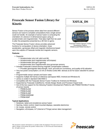
Freescale SemiconductorGetting Started GuideFreescale Cloud-ConnectedZigBee Thermostat Demo 2014 Freescale Semiconductor, Inc. All rights reserved.Document Number: xxxRev. 0.1, 11/2014
How to Reach Us:Home Page:www.freescale.comWeb n in this document is providedsolely to enable system and softwareimplementers to use Freescale products.There are no express or implied copyrightlicenses granted hereunder to design orfabricate any integrated circuits based onthe information in this document.Freescale reserves the right to makechanges without further notice to anyproducts herein. Freescale makes nowarranty, representation, or guaranteeregarding thesuitability of its products for any particularpurpose, nor does Freescale assume anyliability arising out of the application oruse of any product or circuit, andFreescale and the Freescale logo aretrademarks of Freescale Semiconductor,Inc., Reg. U.S. Pat. & Tm. Off.All other product or service names are theproperty of theirrespective owners. 1994-2008 ARC International. Allrights reserved. 2008-2014 Freescale Semiconductor, Inc. All rights reserved.Document Number: xxxRev. 0.1, 11/2014
Table of Contents1 Introduction . 22 System Components . 43 Demo Hardware . 43.1 Preparing Hardware . 53.2 Assemble Tower. 104 Demo Software. 114.1 Firmware Images. 114.2 Demo Projects . 115 Using the Demo . 125.1 Connect Tower to Terminal . 125.2 Loading PEG Resource File . 135.3 Connecting to Wi-Fi Access Point. 145.4 Pairing ZigBee Nodes. 155.5 Demo GUI . 155.6 Cloud Connection . 176 Customizing Demo . 23Freescale Cloud-Connected ZigBee Thermostat Getting Started Guide Rev. 0.1Freescale Semiconductor1
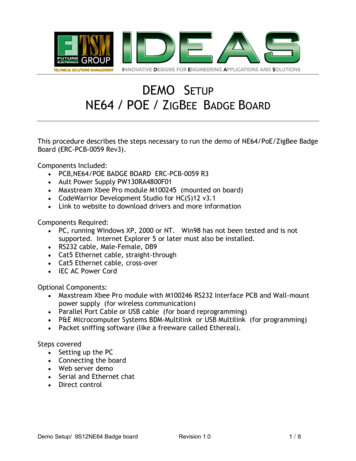
Table of FiguresFigure 1 Thermostat Demo . 3Figure 2 Thermostat Demo System Components . 4Figure 3: TWR-SHIELD Jumper Settings . 6Figure 4: TWR-SHIELD with GT202 Board . 7Figure 5: TWR-KW24D512 Jumper Settings . 7Figure 6: TWR-SER Jumper Settings . 8Figure 7: TWR-K70F120M Jumper Settings . 9Figure 8: TWR-LCD-RGB Jumper Settings . 10Figure 9: Assembled Tower System . 11Figure 10: Terminal Settings . 13Figure 11: Changing and Viewing Wi-Fi Parameters with shell . 14Figure 12: Main HVAC Screen . 15Figure 13: Network Screen . 16Figure 14: HVAC Menu Screen. 17Figure 15 DeviceCloud Account Registration . 18Figure 16 DCIO Device Details page . 19Figure 17 DCIO Mobile App Status Page . 20Figure 18 HVAC system setting page . 21Figure 19 Thermostat Settings page . 221 IntroductionThis reference design is a demo combining several solutions from Freescale and our partners. Thedemo is a thermostat application, using the Kinetis family as a communication gateway between aZigBee network and connecting to the cloud. The demo runs on the Freescale MQX Real-TimeOperating System (RTOS). It also uses the Freescale PEG graphics library for the user interfacedisplayed on an LCD. The ZigBee communication uses Freescale’s BeeStack ZigBee stack, andcan connects with an off-the-shelf ZigBee light bulb, and wirelessly controls it. The demo networkconnection is setup for Wi-Fi, using a Wi-Fi module from Qualcomm. The cloud connection allowsthe thermostat to be monitored and controlled remotely with mobile devices, and uses a solutionprovided by deviceCloud.io.For a sneak peak refer to overview video mo-pageFreescale Cloud-Connected ZigBee Thermostat Getting Started Guide Rev. 0.1Freescale Semiconductor2
Figure 1 Thermostat DemoSmart Thermostat reference demo is based on Kinetis family MCU (K70F120M) and KW24D512zigbee coordinator. The demo kit has HVAC application that controls the heat/cool temperature,hvac mode. The demo kit Connects to WAN via Ethernet or wifi. The embedded DeviceCloud cloudagent provides firewall agnostic instant cloud connectivity. The device can be registered andauthenticated with DCIO cloud platform and the remote temperature sensor can monitored andcontrolled through DCIO Mobile Application.The K70 application is built for Freescale MQX RTOS v4.0.2 and uses Freescale PEG graphicslibrary. The K24 application is built on Freescale MQX-Lite RTOS, uses Freescale connectivity stacklibraries.Freescale Cloud-Connected ZigBee Thermostat Getting Started Guide Rev. 0.1Freescale Semiconductor3
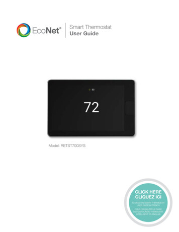
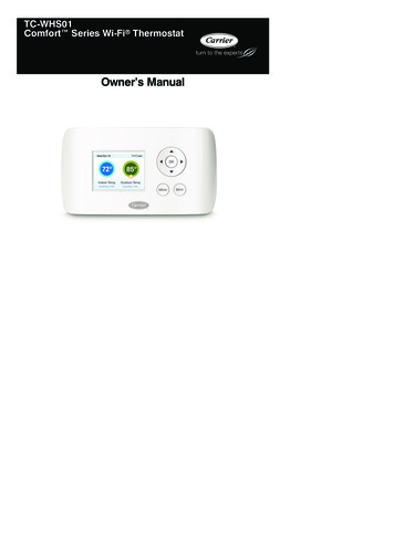
2 System ComponentsThe logical system components used on both K70 and K24 MCU are depicted belowK70 system componentsK24 System componentsHVACApplicationDCIO AgentHVAC libraryBee Appssocket InterfaceBee stackZigbeeRTCSStackFlashdriverWiFi driverLCDIEEE 802.15.4MAC/PHYSPI/I2C driverPlatform ManagementWifi AccessPointZigBee Hue BulbFigure 2 Thermostat Demo System Components3 Demo HardwareThe demo is setup to use the following hardware. If not all of this hardware is available, refer toSection 6 for other options. TWR-K70F120M – main MCU for application. Drives LCD and runs HVAC applicationFreescale Cloud-Connected ZigBee Thermostat Getting Started Guide Rev. 0.1Freescale Semiconductor4
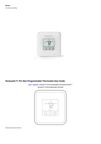
TWR-KW24D512 – ZigBee coordinator for remote temperature sensor and light bulb TWR-LCD-RGB – LCD for GUI Qualcomm GT202 carrier board – Qualcomm eval board with GT202 module, usesQCA4002 Wi-Fi SoC. TWR-SHIELD – allows Qualcomm board to connect to the Tower TWR-SER – Used for USB host to program PEG resource files into K70 NAND flash. TWR-ELEV – both primary and secondary boards USB Adapter Standard-A to mini-ab – used to plug standard USB flash drive into TWR-SERboard to copy PEG resource file Philips Hue ZigBee light bulb and standard lamp to power it – available off-the-shelf USB power supply – to power Tower system. Demo requires more power than manycomputer USB ports provide. Best to power from stand-alone supply, like a phone charger. Access to Wi-Fi access point3.1 Preparing HardwareThe jumper and hardware changes required are detailed below for each board.3.1.1 TWR-SHIELD SetupThe TWR-SHIELD board comes without the headers populated, and the default connects areshorted with traces on the board. The following modifications are required by cutting traces andpopulating the headers, then adding jumpers. Cut Trace J21 between 1-2, (only needed on RevA and earlier. Newer boards do not haveJ21) Cut Trace J68 between 1-2, J68 used for Wi-Fi Power Down signal Remove resistor R85, next to J3, removes conflict between K70 potentiometer and GT202module Need Jumper J68 on 2-3, for Wi-Fi Power Down signal Need Jumper J70 on 1-2, Wi-Fi SPI Chip Select Leave Default - Jumper J65 on 1-2, Wi-Fi SPI Clock Leave Default - Jumper J73 on 1-2, Wi-Fi SPI MOSI Leave Default - Jumper J81 on 1-2, Wi-Fi SPI MISO Leave Default - Jumper J83 on 1-2, Wi-Fi SPI Data Ready signalThe picture below of the TWR-SHIELD board has all the headers populated, but only the requiredjumpers are added.Freescale Cloud-Connected ZigBee Thermostat Getting Started Guide Rev. 0.1Freescale Semiconductor5
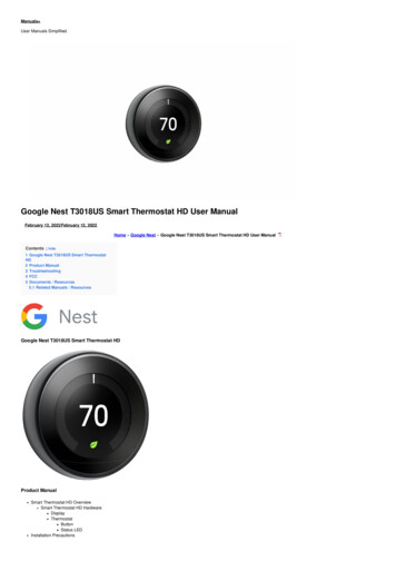
Figure 3: TWR-SHIELD Jumper SettingsAfter modifications are complete, plug the Qualcomm GT202 carrier board into the TWR-SHIELDheaders.Freescale Cloud-Connected ZigBee Thermostat Getting Started Guide Rev. 0.1Freescale Semiconductor6
Figure 4: TWR-SHIELD with GT202 Board3.1.2 TWR-KW24D512 Setup J1 - Set jumper to 5-6 to power card from Elevator J17: oRemove Jumper on 1-2-3: Pin 3 used for WIFI FET ON to K70oNeed Jumper on 5-6: connects KW24 DataAvailablePin to K70oRemove Jumper on 7-8-9: unused connectionoRemove Jumper 10-11-12: conflicts with WIFI SPI MISOJ18 - Remove all JumpersoDisconnects UART1 from Tower, jumpers 1-2-3 and 4-5-6Figure 5: TWR-KW24D512 Jumper Settings3.1.3 TWR-SER SetupThe demo is setup for Wi-Fi, and default jumper settings will work: J16 needs to be on pins 1-2, which is default – this is for USB Host for flash drive with LCDimages.Freescale Cloud-Connected ZigBee Thermostat Getting Started Guide Rev. 0.1Freescale Semiconductor7
If wired Ethernet is desired, the following changes are required. The settings for wired Ethernet willalso work with Wi-Fi: J16 needs to be on pins 1-2, which is default – this is for USB Host for flash drive with LCDimages. J2 CLK SEL needs to be 3-4 – (processor clock is taken from PHY) J3 CLKIN-SEL needs to be 2-3 - (processor clock is taken from PHY) J12 ETH-CONFIG needs 9-10 - to select RMII communication modeThis picture shows the jumper settings above that support both wired Ethernet and Wi-FiFigure 6: TWR-SER Jumper Settings3.1.4 TWR-K70F120MThe demo is setup for Wi-Fi, and the default jumper settings will work for Wi-Fi on this board. But ifwired Ethernet is desired, the following changes are required. The settings for wired Ethernet willalso work with Wi-Fi: J18 on – disables oscillator Y1, and processor clock taken from the TWR-SER boardThis picture shows the jumper settings above that work with both Wi-Fi and wired EthernetFreescale Cloud-Connected ZigBee Thermostat Getting Started Guide Rev. 0.1Freescale Semiconductor8
Figure 7: TWR-K70F120M Jumper Settings3.1.5 TWR-LCD-RGBNo changes are required to this board; the default jumper settings will workFreescale Cloud-Connected ZigBee Thermostat Getting Started Guide Rev. 0.1Freescale Semiconductor9
Figure 8: TWR-LCD-RGB Jumper Settings3.2 Assemble TowerThe ordering of the cards in the Tower slots is not functionally important, but this is therecommended order for using the demo: TWR-SHIELD is on top, with the Qualcomm GT202 carrier board seated in the TWRSHIELD headers TWR-KW24D512 TWR-K70F120M TWR-SER on the bottom TWR-LCD-RGB on the secondary side of the Tower. It will not work on the primary side.Secondary side has the black edge connectors (instead of white)After assembling, power the Tower. With the Tower fully loaded, the demo requires more powerthan many computer USB ports provide. It is recommended to power from stand-alone supply, likea phone charger. Plug the USB Mini plug into the USB jack on the primary elevator card (with whiteedge connectors). There is also a power switch on the other side of the primary elevator card youmay need to toggle to turn on the Tower.Freescale Cloud-Connected ZigBee Thermostat Getting Started Guide Rev. 0.1Freescale Semiconductor10
Figure 9: Assembled Tower System4 Demo SoftwareThe demo uses the 2 MCUs below: Kinetis K70 MK70FN1M0VMJ12 – main MCU, runs HVAC application and drives LCD Kinetis KW24 MKW24D512VHA5 – ZigBee coordinatorThe software release for this demo includes the projects, source code and libraries needed to buildthe applications. Firmware image files are also included that can be programmed into the MCUswithout needing to build the projects.4.1 Firmware ImagesFirmware image files for each MCU are provided in the locations below. These files can beprogrammed into the MCUs using a debugger or programming tool, like IAR and code warrier \Firmware Images\TWR-K70F120M Thermostat Demo \Firmware Images\TWR-KW24D512 Thermostat Demo4.2 Demo ProjectsThe K70 and KW24 projects were tested with IAR Embedded Workbench for ARM v7.30 Thefollowing sections give instructions for building these projects.4.2.1 K70 ProjectThe K70 application is built on Freescale MQX RTOS, and uses the Freescale PEG graphics library.The MQX source code is included for this demo, and the MQX libraries need to be built beforebuilding the application. The PEG source code is not included, but a pre-built library is included forthe project, and the screen source files are included.Freescale Cloud-Connected ZigBee Thermostat Getting Started Guide Rev. 0.1Freescale Semiconductor11
To build the project load the workspace fileTWR-K70F120M Thermostat Demo/os/MQX/config/twrk70f120m/iar/build libs.eww.MQX libraries need to be built first. Use IAR menu Project- Batch Build.Select Debug batch and hit the Make button.After MQX libraries are built , in the workspace window right click the project web HVAC PEGand select “Set as Active” .Make and the download the web HVAC PEG project to theTWR-K70F120M board4.2.2 KW24 ProjectThe KW24 application is built on Freescale MQX-Lite RTOS, and uses the Freescale connectivitystack libraries. The MQX-Lite source code is included for this demo, and the MQX-Lite libraryneeds to be built before building the application.To build the project, use the IAR to load workspace fileTWR-KW24D512 Thermostat Demo/ConnSw Demos/make/DP OnOffSwitch NwkIp/DP OnOffSwitch NwkIp.eww.The MQXLite libraries need to be built first. Right Click MQXLite project in workspace and select“Make”.After the MQXLite libraries are built, In the workspace window right click the projectDP OnOffSwitch NwkIp and select “Set As Active”. Make and then download theDP OnOffSwitch NwkIp project to the TWR-KW24D512 board.5 Using the DemoAfter programming the firmware and assembling the Tower system, there are additional steps tosetup the demo.5.1 Connect Tower to TerminalWhen setting up the demo, it is helpful to use the terminal output from the K70. The terminal can beaccessed through the 9-pin serial connector on the TWR-SER or using the OSJTAG USB virtualCOM port using the USB connector on the TWR-K70F120M board. The demo uses the MQX shelllibrary to accept commands from the user, and setup the demo. In the terminal, type “help” for theavailable shell commands. The terminal settings are 115,200 baud rate, 8 data bits, no parity, 1stop bit, no flow control.Freescale Cloud-Connected ZigBee Thermostat Getting Started Guide Rev. 0.1Freescale Semiconductor12
Figure 10: Terminal Settings5.2 Loading PEG Resource FileThe PEG application uses a resource file for the graphics, fonts, strings, etc. This file is stored infile system mounted by the MQX application at runtime. There are two options for the location ofthe file. It can be stored in the NAND flash on the TWR-K70F120M board, or stored in a USB flashdrive. Using the USB flash drive is useful when developing the GUI, as the file can be replaced onthe flash drive and tested quickly. Once the GUI is complete, the MQX shell can be used to copythe resource file from the USB drive to the NAND drive. If the file is present in both NAND andUSB, the application will use the USB file. Here are the steps for using the resource file.Resource file on USB flash drive:1. Locate the resource file in the project, found at \TWR-K70F120M Thermostat Demo\examples\pro\480x272 32\web hvac PEG\UI\resources.pbr2. Copy this file to the USB flash drive3. Ensure the TWR-SER jumper setting is setup for USB host. The 6-pin header J16 (near theUSB connector) should have a jumper on 1-2, which is default.4. Plug the USB flash drive into the TWR-SER USB connector. An adapter is required to matethe Standard USB A connector of the USB drive to the mini-ab connector on the TWR-SERboard5. Power the Tower, and run the application. After a few seconds, MQX will mount the USBdrive, and PEG will load the resources from the drive, and display the GUI on the LCD. Theterminal output will also show status on mounting the USB drive and reading the file.Resource file on NAND drive:1. Follow the USB steps above to mount the USB flash drive in the MQX application2. Use the shell commands through the terminal to copy the resource file from the USB drive tothe NAND flashFreescale Cloud-Connected ZigBee Thermostat Getting Started Guide Rev. 0.1Freescale Semiconductor13
3. The first time the NAND flash is used on the K70 board, the NAND flash should be erased.Type the command below in the terminal:nanderasechip4. Type the command below to open the NAND file systemfsopen5. The first time the NAND file system is used, it needs to be formatted. Type this command:format a:6. Copy the file from the USB flash drive (c:) to the NAND flash (a:) with this commandcopy resources.pbr a:\resources.pbr7. Close the file system to save the file to NAND:fsclose8. Remove the USB flash drive and reset the K70. The application will now mount the NANDfile system, and load the resource file.9. The next time the file is copied from the USB drive to NAND, the erase and format steps canbe skipped. Use the fsopen, copy and fsclose commands. Also, the MQX file systemsupports other DOS commands for the file system. Type help in the terminal for theavailable shell commands5.3 Connecting to Wi-Fi Access PointThe Wi-Fi parameters can be setup using the shell, and stored in flash. Type “wifi” in the shell tosee the current parameters. To change a parameter, type “wifi set parameter value ”. Thisscreenshot shows changing the SSID parameter to freescale:Figure 11: Changing and Viewing Wi-Fi Parameters with shellWhen changing the parameter settings, the parameter options and values are the following: ssid – string for the Access Point SSID mode – Network Mode for the Access Point. In this demo, only “managed” value is used. sec – Security type used by Access Point. Options are “none”, “wep”, “wpa”, and “wpa2” pass – Password used if the Access Point is secured. If the security type is WEP, this is theWEP key. The value is a string cipher – Encryption cipher type if the security type is WPA or WPA2. The options are“CCMP” or “TKIP”. Note, if the demo attempts a WPA or WPA2 connection and fails, it willattempt with the other cipher option as well. key – The WEP key index if WEP is used. The only option for the demo is 1When the Wi-Fi parameters are correctly configured, the connection can be tested using thecommand “wifi connect”. If the settings work, they can be programmed to flash, and the demo willFreescale Cloud-Connected ZigBee Thermostat Getting Started Guide Rev. 0.1Freescale Semiconductor14
use them automatically after each reset. To program to flash, use the command “wifi program”.The settings in flash can also be erased to return to the default settings using the command “wifierase”. The Qualcomm driver also supports the “wmiconfig” shell command. Refer to theQualcomm documentation for using this command.Default settings are also programmed in the firmware image. If any of the Wi-Fi parameter flashlocations are erased, those parameters will default to the macros in the firmware. These macrosare located in \Projects\HVAC MCU TWRK70F120M\examples\pro\480x272 32\web hvac PEG\hvac.h#define DEMOCFG SSID"freescale"//Possible Values managed or adhoc#define DEMOCFG NW MODE"managed"//Possible vales// 1. "wep"// 2. "wpa"// 3. "wpa2"// 4. "none"#define DEMOCFG SECURITY"wpa2"#define DEMOCFG PASSPHRASE"freescalewifi"//Possible values 1,2,3,4#define DEMOCFG WEP KEY INDEX1#define DEMOCFG DEFAULT DEVICE BSP DEFAULT ENET DEVICE#define DEMOCFG DEFAULT CIPHER CCMP//TKIP or CCMP5.4 Pairing ZigBee NodesIf the ZigBee light bulb is used with the demo, it can be paired with the ZigBee coordinator. Powerthe light bulb, and place it very close to the Tower system. Press SW4 on the TWR-KW24D512board. The LED will start blinking again as the coordinator looks for the light bulb. When thepairing is complete, the LED will stop blinking. This is also stored in flash if the Tower is powercycled. The communication with the light bulb can be tested by pressing SW3 on the TWRKW24D512 board, which will toggle the light bulb.5.5 Demo GUIThis is the Main HVAC screenFigure 12: Main HVAC Screen5.5.1 Displayed TemperatureThe large temperature shown on the right of the screen represents the ambient temperaturemeasured by the HVAC demo. This temperature will work with and without the ZigBee temperaturesensor. When the K70 first boots, it uses a virtual temperature. The demo doesn’t use an actualFreescale Cloud-Connected ZigBee Thermostat Getting Started Guide Rev. 0.1Freescale Semiconductor15
temperature measurement, but adjusts the virtual temperature based on the HVAC state. When theHVAC is in Heat Mode and the Heat set point is greater than virtual temperature, the temperaturewill increase slowly. It increments 1 degree every 5 seconds. Similarly, when the HVAC is in Coolmode, the virtual temperature will decrement slowly.If the K70 receives a temperature report from the ZigBee remote temperature sensor via the KW24,it will stop using the virtual temperature sensor, and will use the measured temperature from theMC13237. The screen is updated with the string “Remote Sensor” above the displayed temperaturewhen the first temperature report is received.When the MC13237 is first paired with the KW24, it can take up to 30s before transmitting the firsttemperature report. After that, it will transmit regularly every few seconds.5.5.2 Main HVAC ScreenThe buttons and temperatures on the left side of the screen are for the Heat and Cool set pointtemperatures. These can be changed using the touchscreen and tapping the up and down arrows.The set point temperatures will also be updated if they are changed using another method, likethrough the cloud or shell.The time and date at the top of the screen is displaying MQX time. Initially, MQX will start with itsdefault initial time. But if the demo has a network connection, it will use SNTP to get the currenttime from an SNTP server, and update the MQX time. The screen will also update every time theMQX minute increments. The demo adjusts for time zone differences after receiving the time fromthe SNTP server. This is done in the firmware using a macro SNTP TIMEZONE defined inTWR-K70F120M Thermostat Demo\examples\pro\480x272 32\web hvac PEG\hvac.hThe HVAC and Fan state are displayed under the large temperature. These will be updated as thestates change. The buttons Network and Menu change the screen for more information. TheZone1 button is for future expansion, and is not currently used.5.5.3 Network ScreenFigure 13: Network ScreenThis screen shows the network status. The IP Address, Subnet mask, and Gateway IP addressvalues are displayed when using Wi-Fi or wired Ethernet, and are updated after the DHCP clientreceives them with a new connection.If Wi-Fi is used, the SSID and security option will be displayed, and updated if they are changedthrough the shell. Also, the status of the Wi-Fi connection is shown. When the Wi-Fi has not yetFreescale Cloud-Connected ZigBee Thermostat Getting Started Guide Rev. 0.1Freescale Semiconductor16
connected, or loses connection, the string “Wi-Fi Not Connected” is shown. Once the connection isestablished, the string is updated with “Wi-Fi Connected”. The cloud connection status is alsodisplayed with a similar string “Cloud Connected”When the demo is connected to the Cloud server, the button “dcio Auth” can be pressed to requestauthentication with the server. If successful, this will print a 4-digit token to the top of the screen.The token can be used with the deviceCloud.io web portal to register the device with a DCIOaccount.5.5.4 HVAC Menu ScreenFigure 14: HVAC Menu ScreenThis screen allows the user to change the HVAC and Fan mode, and the temperature scale. It willalso update when these modes are changed. The Back button returns to the Main HVAC screen.5.6 Cloud ConnectionThe demo uses a cloud connection from deviceCloud.io(DCIO) to provide connectivity . Onceconnected the demo can be monitored and controlled with DCIO’s web site or the DCIO MobileApplication5.6.1 Creating deviceCloud.io accountFirst an account needs to be created to register the demo device with the cloud account.To create account, visit the link http://freescale-hvac-demo.devicecloud.io/fs/This lists 3 steps.1. Register2. Download Binaries3. Get the mobile AppFill in all the details like email, First name, password, organization, Captcha and click on createaccountOn successful creation of the account, email shall be sent to email address provided duringregistration with details of the demo project binaries and user guide.Freescale Cloud-Connected ZigBee Thermostat Getting Started Guide Rev. 0.1Freescale Semiconductor17
The registration page would look as belowFigure 15 DeviceCloud Account RegistrationAfter the device is programmed and connected to the cloud proceed for logging into cloud accountcreated at http://freescale-hvac-demo.devicecloud.io/login . You may login using the email addressand password setup during account creation.Once you login your demo device can be associated with your account using “claim device”.Here are steps to claim device.1. On the device main screen (on device LCD), click network button. On network screen, clickon “dcio Auth” and you will see “DCIO Authenticate Token : xxxx” on top bar2. Click on “Claim device” on the page st3. Enter Token printed in step 1 above as “Device Identifier” and click on “Claim Device”4. Now the device would be visible in Device List.5. Click on the device and device details would show up as belowFreescale Cloud-Connected ZigBee Thermostat Getting Started Guide Rev. 0.1Freescale Semiconductor18
Figure 16 DCIO Device Details pageClick on “Mobile App URL” and enter the email address to receive Mobile App.It would take you to Mobile User register page. You could either register a separate mobile userOr click on existing user and use the credentials used for creating your account.The mobile App would start with status page.Freescale Cloud-Connected ZigBee Thermostat Getting Started Guide Rev. 0.1Freescale Semiconductor19
5.6.2 Using DCIO Mobile AppWhen the user first accesses the mobile App, the status page will be displayed. This page shows asummary of parameters that are monitored by the cloud Agent.Figure 17 DCIO Mobile App Status PageFreescale Cloud-Connected ZigBee Thermostat Getting Started Guide Rev. 0.1Freescale Semiconductor20
Clicking the status page will open a page to change the settings of the demo. The demo parameterscan be changed and when “Save Changes” button is pressed, the cloud server will send theupdated parameters to the thermostat device.Figure 18 HVAC system setting pageFreescale Cloud-Connected ZigBee Thermostat Getting Started Guide Rev. 0.1Freescale Semiconductor21
Figure 19 Thermostat Settings pageFreescale Cloud-Connected ZigBee Thermostat Getting Started Guide Rev. 0.1Freescale Semiconductor22
6 Customizing DemoDemo can be customized if all the hardware components are not available.a. Use wired Ethernet on TWR-SER board instead of wifi.Set the macros below to zero inprojects/TWR-K70F120M Thermostat Demo/os/MQX/config/twrk70f120m/user config.h andrebuild MQX BSP project// For Atheros Wi-Fi driver#define BSPCFG DB142 IOT MODE SUPPORT 0#define BSPCFG ENABLE ATHEROS WIFI0Then set macro below to zero inprojects/mqx/TWR-K70F120M Thermost Demo/examples/pr
Freescale Cloud-Connected ZigBee Thermostat Getting Started Guide Rev. 0.1 Freescale Semiconductor 4 2 System Components The logical system components used on both K70 and K24 MCU are depicted below Figure 2 Thermostat Demo System Components 3 Demo Hardware The demo is setup to use the following hardware.