Transcription
DEMO SETUPNE64 / POE / ZIGBEE BADGE BOARDThis procedure describes the steps necessary to run the demo of NE64/PoE/ZigBee BadgeBoard (ERC-PCB-0059 Rev3).Components Included: PCB,NE64/POE BADGE BOARD ERC-PCB-0059 R3 Ault Power Supply PW130RA4800F01 Maxstream Xbee Pro module M100245 (mounted on board) CodeWarrior Development Studio for HC(S)12 v3.1 Link to website to download drivers and more informationComponents Required: PC, running Windows XP, 2000 or NT. Win98 has not been tested and is notsupported. Internet Explorer 5 or later must also be installed. RS232 cable, Male-Female, DB9 Cat5 Ethernet cable, straight-through Cat5 Ethernet cable, cross-over IEC AC Power CordOptional Components: Maxstream Xbee Pro module with M100246 RS232 Interface PCB and Wall-mountpower supply (for wireless communication) Parallel Port Cable or USB cable (for board reprogramming) P&E Microcomputer Systems BDM-Multilink or USB Multilink (for programming) Packet sniffing software (like a freeware called Ethereal).Steps covered Setting up the PC Connecting the board Web server demo Serial and Ethernet chat Direct controlDemo Setup/ 9S12NE64 Badge boardRevision 1.01/8
1. IntroductionThe NE64 Badge board is an evaluation platform used to demonstrate 3 technologies,Ethernet, ZigBee and Power Over Ethernet (PoE).The board comes preloaded with an application software, a modified version ofFreescale’s AN2836, that implements a 3 way communication bridge function betweenethernet and 2 serial ports on top of a simple web server. A Maxstream ZigBee module isconnected to one of these serial links for RF networking and communication.The ethernet stack used is OpenTCP, a royalty free open source stack. Code size,including support or basic functionality for TCP, UDP, HTTP, POP3, ICMP, ARP, SMTP,DNS, TFTP, etc. is less than 22KB.For simplicity reasons, all the IP addresses and port numbers are static and embedded inthe code at compile time. This can easily be changed.2. Setting up the PCFrom the control panel, Network Connections, right click on your Local Area Connectionand select Properties. (also accessible through the lower left start - settings - network connections)From the list, select the last item Internet Protocol TCP/IP and click on Properties.Demo Setup/ 9S12NE64 Badge boardRevision 1.02/8
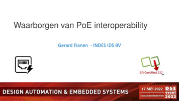
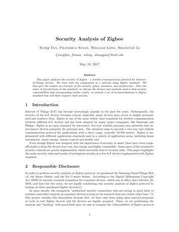
Under the general tab, click the use the following IP address radio button and enter theaddress 192.168.2.1 with a subnet mask of 255.255.255.0 as shown. Pleaseremember these changes; you will need to restore the setting to what it was before.Most computers on a network will have the original setting as Obtain the IP addressautomatically.Click ok and close the Network Connections properties box.You computer now has a static IP address.Demo Setup/ 9S12NE64 Badge boardRevision 1.03/8
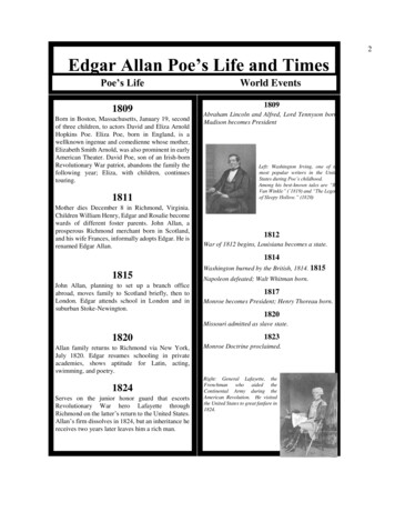
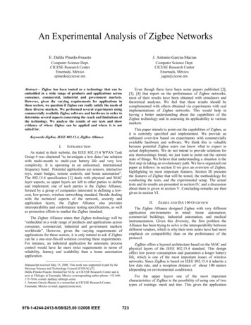
You may also have to click advanced and disable any proxies you may have.Then, open TeraTerm or your favorite terminal program and set the communicationspeed to 115200 baud, 8 bits, 1 stop, no parity and no flow control.Also start the Visual Basic application called NE64 demo.EXE3. Connecting to the boardSerial CableCat 5 Straight CableCat 5 X-over CabledataPCdata powerAultPSNE64XbeeProAC Power CordACApply power to the AULT supply only after all is connected. You should now see a validconnection status in the PC’s status bar.A quick test can be done at this point using a PING command from a DOS window. This istotally optional.Demo Setup/ 9S12NE64 Badge boardRevision 1.04/8
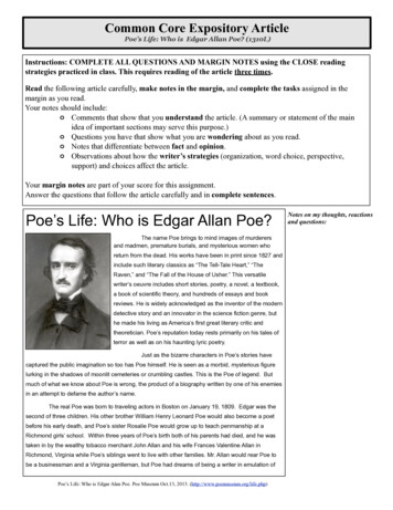
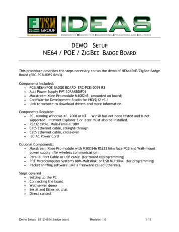
4. Webserver DemoStart the Internet Explorer and type 192.168.2.3 in the address bar as shown below.You should get the following web page displayed. The name index.htm will be addedautomatically since it is the default main page being called by an HTTP GET commandrequested by the web browser.You can navigate to the various pages with the links on the bottom, 3 are shown.Please note that the visual quality of the images is the result of the very high JPEGcompression ratio used. This was necessary to use the minimal amount of storage in theprocessor. Applications using the NE64 as a web server may optionally store the staticHTML and graphics in an external serial flash device interfaced by an SPI or I2C bus. Suchlow pin count devices can readily store megabytes of information leaving the NE64 flashfor application code.Demo Setup/ 9S12NE64 Badge boardRevision 1.05/8
5. Serial chat demoOnce all connected, you can start passing information through the running bridgeapplication by typing some text in the string to send portion of the window.Please note that the whole process is initiated by entering text in the Visual Basicwindow at first!. If text is entered from the serial terminal initially, it will not beretransmitted via ethernet and displayed on the PC. This small issue may be fixed inlater versions.Any text that is typed in or received is being buffered until a carriage return is detected.The string is then sent to the other ports.Some Windows installations may require an ActiveX driver file to be present in theWINDOWS/SYSTEM32 directory, namely Mswinsck.ocx. If you get the error messagewhen launching the VB application, you can download this file from our web site (seesection 8 of this document) and copy it to your windows/system32 directory. We havealso seen some systems asking for a richtx32.ocx driver file. It can also be downloadedand installed in the same directory.Demo Setup/ 9S12NE64 Badge boardRevision 1.06/8
6. Direct Control and local EventsYou may also enter the following commands through the Visual Basic application tocontrol some hardware.-“l1n”“l2n”“l1f”“l2f”will turn led 1 on.will turn led 2 on.will turn led 1 offto turn led 2 off.(do not enter the “ ”, only the 3 characters in between)Turning the trim pot will send screen updates through the network and will display onthe VB application under NE64 pot xxx with xxx being a decimal value from 0 to 1023(taken from the on chip 10 bit A/D converter)Pressing a button will create a ButtonX down event and releasing it will create aButtonX up event, sending a specific string over the ethernet. Button1 will turn on led 2while Button2 will turn it off.Demo Setup/ 9S12NE64 Badge boardRevision 1.07/8
7. RF chatAnother NE64 Badge board with identical setup can be used to demonstrate RFcommunication and implement a simple wireless text chat.No specific control strings are sent to the Maxstream modules upon reset, the defaultconfiguration is used as is.Maxstream also have a stand alone adapter that can hook an RS232 serial link or USBport to another XBee module. Part number M100246.8. For more InformationTo access all the pertinent information related to this project, please go to the followingwebsite: (You will be asked for a user name and password, both of these are case sensitive).http://www.futureerc.com/ne64badgeUser Name:Password:ne64badgene64badgeThe source code is available by request only. It is a modified version of AN2836 available fromthe Freescale web site.Demo Setup/ 9S12NE64 Badge boardRevision 1.08/8
The NE64 Badge board is an evaluation platform used to demonstrate 3 technologies, Ethernet, ZigBee and Power Over Ethernet (PoE). The board comes preloaded with an application software, a modified version of Freescale's AN2836, that implements a 3 way communication bridge function between ethernet and 2 serial ports on top of a simple web server. A Maxstream ZigBee module is connected to .