Transcription
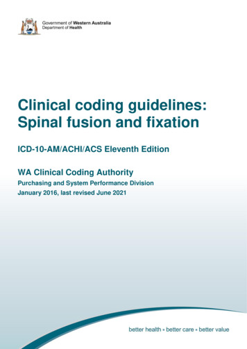
Freescale Semiconductor, Inc.Data Sheet: Product PreviewXSFLK DSRev 0.6, 9/2014Freescale Sensor Fusion Library forKinetisXSFLK DSSensor Fusion is the process where data from several differentsensors are fused to complete computations that a single sensorcould not handle. An example of sensor fusion is computing theorientation of a device in 3-dimensional space using anaccelerometer and magnetometer. That data might then be usedto alter the perspective presented by a 3D GUI or game.The Freescale Sensor Fusion Library provides advancedfunctions for computation of device orientation, linearacceleration, gyroscope offset and magnetic interference basedupon the outputs of Freescale inertial and magnetic sensors.Freescale Freedom Sensors ToolboxDevelopment PlatformFRDM-KL25Z/FRDM-FXS-MULTIFeatures Supports: Accelerometer only (roll, pitch and tilt) Accelerometer plus magnetometer (eCompass) Accelerometer plus gyro (gaming) Accelerometer plus magnetometer plus gyroscope sensors Includes Freescale’s award-winning magnetic compensation software Provides geomagnetic field strength, hard- and soft-iron corrections, and quality-of-fit indication Very low power consumption ( 5 mA on Kinetis Cortex M0 devices at 25 Hz fusion rate/200 Hz sensorrate) Programmable sensor sample and fusion rates Supports multiple 3D frames of reference (aerospace NED, Android and Windows 8) Library is coded in standard C99 ANSI C Compatible with the Freescale Sensor Fusion Toolbox for Android and Windows Supported by Freescale CodeWarrior, Kinetis Design Studio and Processor Expert tools Out-of-the box support for the following Freedom Development Platforms with FRDM-FXS-MULTI familyof sensor boards FRDM-KL25Z FRDM-KL26Z FRDM-KL46Z FRDM-K20D50M FRDM-K64FTypical Applications Notebook, tablet and smartphone sensor fusion Gaming, motion control, head-mounted displays, wearable electronics Air mouse, remote control Navigation, eCompass, IoT (Internet of Things) sensor data managementThis document contains information on a product under development. Freescale reserves theright to change or discontinue this product without notice. 2014 Freescale Semiconductor,Inc. All rights reserved.
Table 1. Feature Comparison of the Freescale Sensor Fusion AlgorithmOptionsFeatureAccel onlyAccel gyroAccel magAccel mag gyroLow passIndirectKalmanLow pass1Indirect KalmanRoll / Pitch / Tilt in degreesYesYesYesYesYaw in degreesNoNoYesYesYesvirtual 3 axisYesFilter typeAngularrate2in degrees/secondvirtual 2axis3Compass heading (magnetic north) in degreesNoNoYesYesQuarternion and rotation vectorYesYesYesYesRotation matrixYesYesYesYesLinear acceleration separate from gravityNoYes4YesNED (North-East-Down) frame of referenceYesYesYesENU (Windows 8 variant) frame of referenceYes4Yes4YesYesENU (Android variant) frame of referenceYes4Yes4YesYesMagnetic calibration includedNoNoYesYesGyro offset calibration includedN/AYesN/AYesFRDM-KL25Z board supportYesYesYesYesFRDM-KL46Z board supportYesYesYesYesFRDM-K20D50M board supportYesYesYesYesFRDM-KL26Z board supportYesYesYesYesFRDM-K64F board supportYesYesYesYes1.2.3.4.YesNo4More precisely: a non-linear modified exponential low pass quaternion SLERP filter.Angular rate for configurations with a gyro include corrections for gyro offset.Subject to well-known limitation of being blind to rotation about axes aligned with gravity.These solutions do not include a magnetometer, therefore there is no sense of compass heading .Feature OptionsFeatureLicenseCPU selectionOptionsFree to use with Freescale components, see the license file for 46Z256VMC4MK64FN1M0VLL12Board customizableYes1, 2, 3Sensor sample rateProgrammableFusion rateProgrammableFrame of ReferenceProgrammableAlgorithms ExecutingProgrammableTable continues on the next page.2Freescale Semiconductor, Inc.Freescale Sensor Fusion Library for Kinetis, Rev0.6, 9/2014.
Feature Options (continued)FeatureOptionsSleep mode enabled betweensamples/calculationsProgrammableRTOSCode flexibilityMQX-LiteOnly Kalman and MagCal libraries are precompiled. All other files are supplied insource form, and can be modified. Full source code is provided.Access to Processor ExpertProduct DeliverablesYes This datasheet Installer, which includes documentation and the appropriate CodeWarriorproject(s) Software user guide Kinetis Design Studio (KDS)1. Listed MCUs are those supported by included project templates. The fusion library should be portable to any ARM processor without change. Ports to other architectures are expected to be very straightforward, as the library is writtenin standard C.2. FRDM-KL25Z, FRDM-KL26Z, FRDM-KL46Z, FRDM-K20D50M and FRDM-K64F are supported out-of-the box andmay be used as templates for other boards.3. The sensor fusion library was written assuming the MQXLite RTOS, but should be easily adaptable to other operatingsystems. See the "Freescale Sensor Fusion for Kinetis User Guide" for additional details.The Freescale Sensor Fusion Toolbox includes the FRDM KL46Z special project that is designed todemonstrate the accelerometer and magnetometer sensor fusion algorithms using the FXOS8700combination sensor present on the FRDM-KL46Z Freedom Development Platform. No sensor shield board isneeded in this configuration and this results in a very low-cost demonstration platform. The FRDM KL46Zproject is compatible with the Sensor Fusion Toolbox for Windows over USB connection but the project canalso be used as a stand-alone since the compass heading is displayed directly on the FRDM-KL46Z LCDdisplay. The Sensor Fusion algorithms that require a gyroscope sensor are not supported in this instancesince there is no gyroscope sensor on the FRDM-KL46Z Freedom Development Platform, so they can beremoved.The sensor sampling, sensor fusion and magnetic algorithms run as a single task at 25Hz. On power up, thegreen LED flashes slowly to indicate that the software is executing but that there is no magnetic calibrationsolution. The green LED then flashes rapidly to signal that the compass heading display is accurate and thata valid magnetic calibration has been obtained after rotating the FRDM-KL46Z board.Freescale Sensor Fusion Library for Kinetis, Rev0.6, 9/2014.3Freescale Semiconductor, Inc.
Table of Contents1 Functional Overview.51.1 Introduction. 51.2 Accelerometer Only.51.3 Accelerometer Plus Magnetometer. 61.4 Accelerometer Plus Gyroscope. 61.5 Accelerometer Plus Magnetometer Plus Gyroscope. 72 Additional Support. 82.1 Freescale Sensor Fusion Toolbox for Android.82.2 Freescale Sensor Fusion Toolbox for Windows.92.3 Terms and Acronyms. 112.4 References. 123 Mechanical and Electrical Specifications. 123.1 General Considerations. 123.2 Hardware Platforms Used to Measure Performance. 133.3 Simulation Environments. 163.4 Frame of Reference. 183.5 Electrical Specifications. 183.6 Computation Metrics. 214Freescale Semiconductor, Inc.3.7 Magnetic Calibration Metrics.233.8 Fusion Model Performance Metrics. 254 Test Descriptions.324.1 MCU Current.324.2 Flash and RAM Required.334.3 Fusion & MagCal Loop Execution Time. 344.4 Compass Heading Linearity and Accuracy. 354.5 Orientation Static Drift. 364.6 Orientation Static Noise. 374.7 Orientation Dynamic Drift. 384.8 Maximum Angular Rate. 384.9 Orientation Response Delay. 394.10 Orientation Magnetic Immunity (Static Device).404.11 Orientation Magnetic Immunity (Moving Device). 414.12 Error in Computed Gyro Bias.414.13 Gyro Offset Step Response. 424.14 Error in Computed Linear Acceleration. 425 Revision history for XSFLK DS. 43Freescale Sensor Fusion Library for Kinetis, Rev0.6, 9/2014.
Functional Overview1 Functional Overview1.1 IntroductionSensor fusion encompasses a variety of techniques that: Trade off strengths and weaknesses of the various sensors to compute somethingmore than can be calculated using the individual components Improve the quality and noise level of computed results by taking advantage of: Known data redundancies between sensors Knowledge of system transfer functions, dynamics and kinematicsThe Freescale Sensor Fusion Library for Kinetis (Fusion Library) supports severalcombinations of sensors. In general, performance improves as more sensors are addedto the system. The primary function of the library is to compute orientation of a sensorsubsystem relative to a global frame of reference.Orientation can be expressed in a number of different ways: Tilt from vertical (may also be expressed as roll pitch) Compass heading (geomagnetic north) Full 3D rotation from a global frame in any of the following forms: Rotation matrix Rotation vector (3D axis of rotation and rotation about that axis) Quaternion Euler angles (roll, pitch and yaw)For additional portability details and guidelines refer to the Freescale Sensor Fusionfor Kinetis MCUs User Guide which is part of the Sensor Fusion Library installation.The Fusion Library is available in source code form. The fusion library is designed tosit on top of board abstractions provided by Processor Expert and MQXLite. Most ofthe C source and header files in the Sources directory of the project templates areboard and MCU independent. If a particular board does not bring out the GPIO, I2Cor UART needed, the board will not be compatible with the software and thereforewill not be supported by Processor Expert.Freescale Sensor Fusion Library for Kinetis, Rev0.6, 9/2014.5Freescale Semiconductor, Inc.
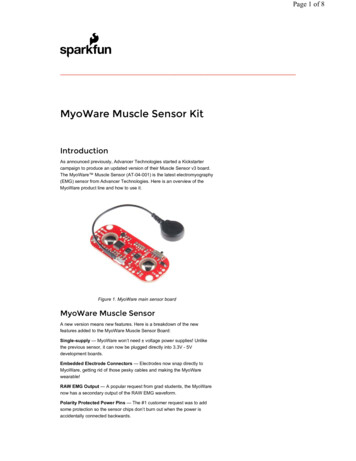
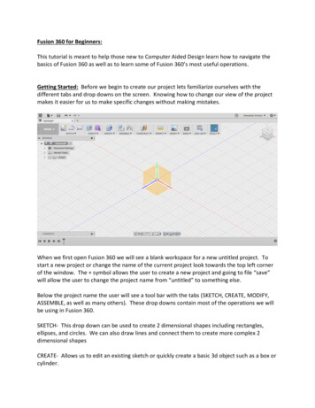
Functional Overview1.2 Accelerometer OnlyAn accelerometer measures linear acceleration minus gravity. If linear acceleration iszero, this sensor can be used to measure tilt from vertical, roll and pitch. Computationof yaw is not supported by this configuration.Accelerometer signalCompute orientationLow pass filterOrientationFigure 1. Accelerometer only block diagram1.3 Accelerometer Plus MagnetometerThe accelerometer plus magnetometer configuration is often used as an electroniccompass. The electronic compass is subject to the linear acceleration equals zero,assumption. Accuracy is dependent upon negligible magnetic interference from theenvironment in which the sensors travel.Accelerometer signalCompute orientationMagnetometer signalLow pass filterOrientationMagnetic calibrationFigure 2. Accelerometer plus magnetometer block diagram1.4 Accelerometer Plus GyroscopeUsing a gyroscope in addition to an accelerometer yields the ability to smoothlymeasure rotation in 3D space, although the system can only yield orientation to somerandom horizontal global frame of reference. That is, the system has no sense ofmagnetic north. Computation of yaw is not supported by this configuration.This configuration is commonly known as an Inertial Measurement Unit (IMU).6Freescale Semiconductor, Inc.Freescale Sensor Fusion Library for Kinetis, Rev0.6, 9/2014.
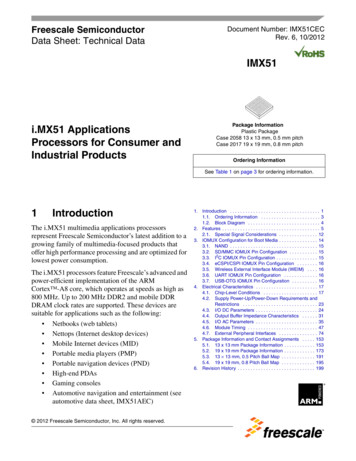
Functional OverviewLinear acceleration, orientation errorAccelerometer signalAccelerometer-basedinclination modelKalman filterGyro signalOrientation gyro offestGyro-basedinclination modelGyro offset, orientation errorFigure 3. Accelerometer Plus Gyroscope Block Diagram1.5 Accelerometer Plus Magnetometer Plus GyroscopeSometimes referred to as Magnetic, Angular Rate and Gravity (MARG), thissubsystem offers an optimal combination of sensors for smooth tracking of orientationand separation of gravity and linear acceleration. This system is capable of yieldingabsolute orientation data with respect to magnetic north.Linear acceleration, orientation errorAccelerometer signalGyro signalAccelerometer-basedinclination modelGyro offset, orientation errorGyro-basedinclination modelMagnetometer signalMagnetic calibrationKalman filterOrientationGyro offsetMagnetic disturbanceLinear accelerationMagnetometer-basedinclination modelMagnetometer disturbance, orientation errorFigure 4. Accelerometer Plus Magnetometer Plus Gyroscope Block DiagramFreescale Sensor Fusion Library for Kinetis, Rev0.6, 9/2014.7Freescale Semiconductor, Inc.
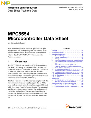
Additional Support2 Additional SupportFreescale Sensor Fusion Toolbox provides support for both Android and Windowsoperating systems. See Table 2 for the differences between the two implementations.Table 2. Freescale Sensor Fusion Toolbox Features by PlatformFeatureAndroidPCBluetooth wireless link Requires BT on PC (built-in or dongle)Ethernet wireless linkOn WiGo board only-UART over USB- 1OS requirements Android 3.0 Windows 7.0Support for native sensors -Device View Panorama View -Statistics View -Canvas View -Orientation XY Plots- Inertial XY Plots- Magnetics- Kalman- Altimeter XY Plots- Data Logging Integrated documentation Google PlayFreescale websiteFreeFreeAvailabilityPrice1. FRDM K64F and FRDM K20D50M projects require a Processor Expert configuration change to run in wired mode.2.1 Freescale Sensor Fusion Toolbox for AndroidThe Fusion Library is supplied in the form of CodeWarrior projects for specificFreescale development boards. The basic function of the Sensor Fusion Androidimplementation are shown in Figure 5 These projects are compatible with the FreescaleSensor Fusion Toolbox for Android, which can be freely downloaded from GooglePlay. For download and training links, see Http://www.freescale.sensorfusion.8Freescale Semiconductor, Inc.Freescale Sensor Fusion Library for Kinetis, Rev0.6, 9/2014.
Additional SupportSensor selectionSensorsnative to yourAndroid deviceAlgorithm cs ViewLog ViewDevice ViewBadWorstPanorama ViewOutput selectionFigure 5. Freescale Sensor Fusion Toolbox for Android Basic Functions2.2 Freescale Sensor Fusion Toolbox for WindowsThe Sensor Fusion Toolbox includes an equivalent version of the software forWindows. For download and training links, see http:/www.freescale.com/sensorfusion.Figure 6 and Figure 7 are Sensor Fusion Toolbox screenshots of the Windows version.Freescale Sensor Fusion Library for Kinetis, Rev0.6, 9/2014.9Freescale Semiconductor, Inc.
Additional SupportFigure 6. PC Version - Device View TabFigure 7. PC Version - Magnetics Tab10Freescale Semiconductor, Inc.Freescale Sensor Fusion Library for Kinetis, Rev0.6, 9/2014.
Additional Support2.3 Terms and AcronymsDUTDevice Under TestENUA global frame of reference described by X East, Y North, Z Upgabbreviation for gravities. 1 standard gravity 9.80665 m/s2. Accelerometers are commonly trimmedusing the local gravimetric field, which can vary by 1/2 percent depending upon altitude and latitude.gaussCGS system unit for measuring magnetic field strength. 100 μT 1 gauss.IMUInertial Measurement Unit accelerometer gyroKinetisFreescale family of ARM -based MCUsMagCalMagnetic CalibrationMARGMagnetic Angular Rate Gravity IMU magnetometerMCUMicro-Controller UnitmicroTeslaThe Tesla is the SI unit for measuring magnetic field strength. 1E–4 Tesla 100 μT 1 gaussNEDA global frame of reference described by X North, Y East, Z DownpitchIn the Aerospace/NED frame of reference, defined as a rotation about the Y-axisRHRRight Hand Rule—a standard convention for describing the positive/negative sense of rotations about anaxis of rotation. See http://en.wikipedia.org/wiki/Right hand rule.rollIn the Aerospace/NED frame of reference, defined as a rotation about the X-axisRPYRoll, Pitch, and Yaw. In the Aerospace/NED frame of reference these are defined as rotations about the Xaxis,Y axis, and Z axisYawΨRPY anglesXRollΦZBody frameYPitchθSIInternational System of Units (meter, kilogram, second, .)SLERPSpherical Linear intERPolation - See http://en.wikipedia.org/wiki/SLERPSysTickA feature of the ARM processor; a clock timer which for the purposes of this discussion, 1 sysTick 1CPU clock cycle.tiltAngle from verticalTable continues on the next page.Freescale Sensor Fusion Library for Kinetis, Rev0.6, 9/2014.11Freescale Semiconductor, Inc.
Mechanical and Electrical SpecificationsUARTUniversal Asynchronous Receiver / Transmitter, also known as SCI (Serial Communications Interface)yawIn the Aerospace/NED frame of reference, defined as a rotation about the Z-axis2.4 References1. "Orientation Representations: Part 1" at dded-beat/blog/2012/ 10/29/orientation-representations-part-12. "Orientation Representations: Part 2" at dded-beat/blog/2013/ 01/22/orientation-representations-part-23. "Hard and soft iron magnetic compensation explained" at ddedbeat/ ation-explained4. CodeWarrior Integrated Development Environment Software at freescale.com/codewarrior5. Kinetis Design Studio Integrated Development Environment6. "Euler Angles" at http://en.wikipedia.org/wiki/Euler Angles7. "Introduction to Random Signals and Applied Kalman Filtering", 3rd edition, byRobert Grover brown and Patrick Y.C. Hwang, John Wiley & Sons, 19978. "Quaternions and Rotation Sequences", Jack B. Kuipers, Princeton UniversityPress, 19999. Freescale Freedom development platform home page at freescale.com/freedom10. OpenSDA User’s Guide, Freescale Semiconductor, Rev 0.93, 2012-09-1811. PE micro Open SDA Support12. PE micro Embedded OSBDM support13. Matlab computer software by ab/3 Mechanical and Electrical Specifications3.1 General ConsiderationsFusion algorithms can be tuned to trade off one performance parameter versus another.Examples include: Speedy handling of magnetic interference versus slower convergence to magneticnorth12Freescale Semiconductor, Inc.Freescale Sensor Fusion Library for Kinetis, Rev0.6, 9/2014.
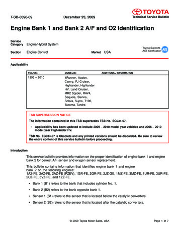
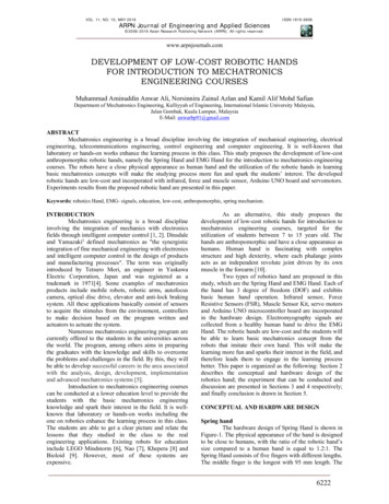
Mechanical and Electrical Specifications Smoothness versus responsiveness Accuracy versus bandwidthNOTEAll of the above means that there is no one correctconfiguration. Accordingly, this datasheet presents typicalperformance as observed on the sample projects supplied byFreescale on specific Freescale development platforms.3.2 Hardware Platforms Used to Measure PerformanceIn the following subsections, some parametrics are measured, some representsimulated results. There are multiple methods used to determine parametrics. Thesemake use of hardware platforms for benchmarking purposes, in addition to Matlab.Kinetis Cortex M0 This configuration is composed of a Freescale KL25Z, KL46Z or KL26Z Freedomdevelopment platform paired with a FXS-MULTI-B Bluetooth-enabled sensor board.Use of Bluetooth allows the board to be rotated freely, untethered by cords or powercables.Table 3. Cortex M0 Test ConfigurationComponent / ParameterBaseboardValueFRDM-KL25Z / FRDM-KL26Z / FRDM-KL-46ZSensor BoardFRDM-FXS-MULTI-BMCUKinetis MKL25Z128VLK4 / MKL26Z128VLH4 / MKL46Z256VMC4CPUARM Cortex M0 CPU Clock48 MHzBus Clock24 S21000Sensor Sampling Rate200 HzFusion Rate25 HzMagnetic Calibration RateVariesThis board combination is battery powered and nominally regulated to 3.3 V for useby the sensors in question.Freescale Sensor Fusion Library for Kinetis, Rev0.6, 9/2014.13Freescale Semiconductor, Inc.
Mechanical and Electrical SpecificationsFigure 8. FRDM-KL25Z / FRDM-FXS-MULTI-B sensor fusion prototype platformBluetoothmoduleJ10J1BT ResetFXOS8700BT .3 VpowerjumperFXAS21000*J1-1: BT RXOJ1-2: TXOJ1-3: MAGJ1-4: TP FRDM DIG03J1-5: INT ACCELJ1-6: INT GYROJ1-7: TP FRDM DIG06J1-8: TP FRDM DIG07J2-1: INT PEDJ2-2: TP FDRDM DIG09J2-3: SPI SS SPI ACCELJ2-4: SPI MOSIJ2-5: SPI MISOJ2-6: SPI CLKJ2-7: GNDJ2-8: AREFJ2-9: I2C SDA0J2-10: I2C SCL0J10-6: I2C SCL1J10-5: I2C SDA1J10-4: SNS LIGHTJ10-3: SPI SS SDJ10-2: BT MONITORJ10-1: BT WAKEUPJ9-8: NCJ9-7: GNDJ9-6: GNDJ9-5: 5 V USB INPUTJ9-4: 3.3 VJ9-3: RST TGTMCU BJ9-2: 3.3 VJ9-1: NCJ9J2SD cardOn/OffswitchFRDM FXS MULTI-B CalloutsFRDM FXS MULTI-B Pinout* For production status, go to freescale.com/FXAS21000Figure 9. Expanded Diagram of FRDM-FXS-MULTI-B Sensor Board14Freescale Semiconductor, Inc.Freescale Sensor Fusion Library for Kinetis, Rev0.6, 9/2014.
Mechanical and Electrical SpecificationsKinetis Cortex M4Table 4. Kinetis Cortex M4Component / ParameterValueBaseboardFRDM-K20D50MSensor BoardFRDM-FXS-MULTI-BMCUKinetis MK20DX128VLH5CPUARM Cortex M4CPU Clock48 MHzBus Clock24 S21000Sensor Sampling Rate200 HzFusion Rate25 HzMagnetic Calibration RateVariesThis board combination is battery powered and nominally regulated to 3.3 V for useby the sensors in question. Physically, the FRDM-K20D50M / FRDM-FXS-MULTIB board combination is similar to the KL25Z variant shown in Figure 8, with theexception that the bottom board is red.Kinetis Cortex M4 with FPUTable 5. Kinetis Cortex M4 with FPUComponent / ParameterValueBaseboardFRDM-K64FSensor BoardFRDM-FXS-MULTI-BMCUKinetis MK64FN1M0VLL12CPUARM Cortex M4 with FPUCPU Clock120 MHzBus Clock60 S21000Sensor Sampling Rate200 HzFusion Rate25 HzMagnetic Calibration RateVariesFreescale Sensor Fusion Library for Kinetis, Rev0.6, 9/2014.15Freescale Semiconductor, Inc.
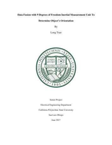
Mechanical and Electrical SpecificationsThe FRDM-K64F / FRDM-FXS-MULTI-B board combination is similar to the KL25Zvariant shown in Figure 8, except that the bottom base board is different.3.3 Simulation EnvironmentsMany parameters are difficult, if not impossible, to reliably measure in a lab orproduction environment. Ambient magnetic fields vary tremendously in indoorenvironments. Determining filter sensitivities to various input parameters can only bedone in a simulated environment.Accordingly, the subsequent sub-sections discuss environments that may be used toexplore these areas.Pure MatlabMatlab is commonly used in the early development of sensor fusion algorithms. It canbe used to model physical stimulus, expected responses and filter operation. See thenext section for details concerning sensor and environmental models used to constructstimulus.Matlab Stimulus/Expected Response Hardware-based FusionOnce algorithms are functional, they are translated into C, optimized and thenoptimized again. The result often makes use of fixed point arithmetic running on anMCU to compute results. To ensure bit-accurate results, a mixture of Matlab (used togenerate test stimulus and expected response) and hardware (used to run the filter) areused to determine many parameters.Figure 10. Mixed Simulation/Hardware Characterization16Freescale Semiconductor, Inc.Freescale Sensor Fusion Library for Kinetis, Rev0.6, 9/2014.
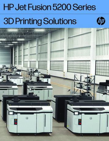
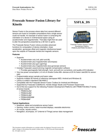
Mechanical and Electrical SpecificationsUnless stated otherwise elsewhere, parameters used to create the simulated sensorsand environment are: Earth magnetic field corresponding to U.S. zip code 85284 (Tempe, Arizona) on7November 2013 as determined using the NOAA calculator at ngdc.noaa.gov/geomag-web Declination: 10 degrees 39’ 36” Inclination: 59 degrees 32’ 53” Horizontal Intensity: 24.2976 μT North Component ( N -S): 23.8782 μT East Component ( E -W): 4.4945 μT Vertical Component ( D -U): 41.3285 μT Total field: 47.9418 μT Ideal accelerometer model simple noise Sample rate 200 Hz 1.0 milli-g noise on X,Y,Z 1 g 9.80665 m/s2 assumed Ideal magnetometer model simple nose Sample rate 200 Hz X, Y noise 0.85 μT; Z noise 1.3 μT No hard/soft iron distortion Ideal gyroscope model and simple noise Sample rate 200 Hz X, Y, Z noise 0.3 dpsFor all tests, the Freescale Matlab-based Trajectory & Sensor Simulation Toolkit(TSim) is used to create DUT trajectories and simulated sensors readings.Some of the tests require that magnetic calibration procedure is run before the test toinitialize the sensor fusion software magnetic buffer. Magnetic calibration isimplemented as a trajectory made up of a sequence of random rotations lasting30seconds.Benchtop Rotary TableA variant on the Matlab-based system is shown in Figure 11. In this case, Matlab isused to control a desktop rotary table and to post-process the fusion results intoreports. Physical sensor readings are used to drive the fusion routines. Because indoorenvironments vary magnetically, results may vary from day to day as the setup ismoved or electronics in the area cycle on and off.Results will also change simply because the state of the magnetic buffer iscontinuously updated.Freescale Sensor Fusion Library for Kinetis, Rev0.6, 9/2014.17Freescale Semiconductor, Inc.
Mechanical and Electrical SpecificationsconfigurationcommandsEmbedded board runningfusion libraryPC running Matlabcomputed sensorfusion resultsNon-ferrousstand designed to actas “spacer” between tableand sensorsPerformance Metricsrotary platformUSB-to-serialadapter cableExcitron MRT7-57-25 7”motorized rotary tablerotary table commandsFigure 11. Benchtop Rotary Table Setup3.4 Frame of ReferenceTable 6 summarizes differences between the standard frames of reference supported bythe fusion library.Table 6. Frame of Reference VariationsNEDAndroidWindows 8Axes alignmentNEDENUENUAngle rotation orderYaw then pitch then rollYaw then roll then pitchYaw then pitch then rollGimbal lockRoll instability (x axis) at 90deg pitch (y axis)Pitch instability (x axis) at 90 Roll instability (y axis) at 90deg roll (y axis)deg pitch (x axis)Roll range1Clockwise –180 to 180 degAnti-clockwise –90 to 90 degClockwise –90 to 90 degPitch range–90 to 90 deg–180 to 180 deg–180 to 180 degYaw range0 to 3600 to 3600 to 360Compass headingYawYaw–Yaw1. A clockwise rotation is defined as one that is positive in the Right-Hand-Rule (RHR) sense.18Freescale Semiconductor, Inc.Freescale Sensor Fusion Library for Kinetis, Rev0.6, 9/2014.
Mechanical and Electrical Specifications3.5 Electrical SpecificationsThe parameters in each table are measured using the configurations defined inHardware Platforms Used to Measure Performance. The MCU currents are measuredwith MCU stop mode enabled in idle task and UART communication disabled.NOTEFor all the tables in this section, the data in the Demo configcolumn uses all four algorithms to the left of the columnrunning concurrently. Also, these tables were developedusing the build #417 of the Sensor Fusion Library.Table 7. FRDM-KL25Z Algorithms Execution TimesMetricAccelAccel Mag,Accel Gyro9 DOFDemo configunitsonlyeCompassAlgorithm execution time,max; see MCU Current1.11.835.71019msMagCal execution time,max; see Fusion &MagCal Loop ExecutionTimeN/A320N/A420560msTest Conditions (unless otherwise specified)MCU clock source: PLL 48MHz, core clock 48MHz, bus clock 24MHzTable 8. FRDM-KL26Z Algorithm Execution TimesMetricAccel onlyAccel Mag,eCompassAccel Gyro9 DOFDemo configunitsAlgorithm execution time,max; see MCU Current1.11.835.71019msMagCal execution time,max; see Fusion &MagCal Loop ExecutionTimeN/A320N/A420560msTest Conditions (unless otherwise specified)MCU clock source: PLL 48MHz, core clock 48MHz, bus clock 24MHzTable 9. Additional Electrical Specifications for FRDM-KL26Z onlyFunctionFusion Idd @ 25Hz rateFusion Idd /HzAccel only0.240.0102D Mag0.190.007Gyro only0.690.028Accel Mag eCompass0.310.012Table continues on the next page.Freescale Sensor Fusion Library for Kinetis, Rev0.6, 9/2014.19Freescale Semiconductor, Inc.
Mechanical and Electrical SpecificationsTable 9. Additional Electrical Specifications for FRDM-KL26Z only (continued)FunctionFusion Idd @ 25Hz rateFusion Idd /HzAccel ated RTOS/other2.040.082Table 10. FRDM-K20D50M Algorithm Execution TimesMetricAccel onlyAccel Mag,eCompassAccel Gyro9 DOFDemo configunitsAlgorithm execution time,max; see MCU Current0.651.12.86.111.2msMagCal execution time,max; see Fusion &MagCal Loop ExecutionTimeN/A140N/A215215msTest Conditions (unless otherwise specified)MCU clock source: PLL 48MHz, core clock 48MHz, bus clock 24MHzTable 11. FRDM-K64F Algorithm Execution TimesMetricAccel onlyAccel Mag,eCompassAccel Gyro9 DOFDemo configunitsAlgorithm execution time,max; see MCU Current0.1260.280.290.561.15msMagCal execution time,max; see Fusion &MagCal Loop ExecutionTimeN/A15N/A1515msTest Conditions (unless otherwise specified)MCU clock source: PLL 50MHz, c
Freescale Sensor Fusion Toolbox provides support for both Android and Windows operating systems. See Table 2 for the differences between the two implementations. Table 2. Freescale Sensor Fusion Toolbox Features by Platform Feature Android PC Bluetooth wireless link Requires BT on PC (built-in or dongle) Ethernet wireless link On WiGo board only -