Transcription
ADC-T3000SMART THERMOSTAT 2Product Manual
SMART THERMOSTAT 2 Product Manual 1 Before installing or servicing the thermostat, turn offpower to the system at the circuit breaker. Leave power off until you have finished installingor servicing. Shorting the electric terminals at the control on theheating or cooling system may damage the thermostat.Do not test the system this way. You must follow all local codes and ordinances for wiringthe system. This thermostat should only be powered by 2 AAA alkalinebatteries or a listed class 2 power supply at 24 VAC(C-Wire or wall transformer). An amperage higher than 1 amp through each thermostatterminal may cause damage to the thermostat. Verify that the system is 24 VAC. If the old system is labeledas 120 or 240 volts or has wire nuts, the system is highvoltage. Do not install the thermostat to a high voltagesystem. Contact a local HVAC professional for help.
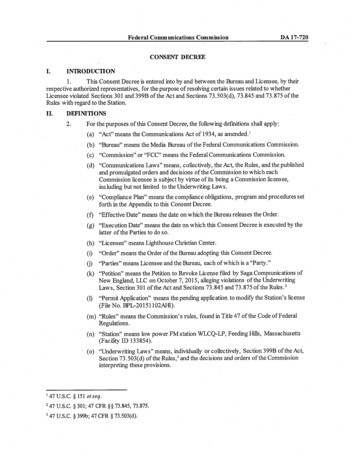
SMART THERMOSTAT 2Product Manual 32 SMART THERMOSTAT 2 Product ManualTHERMOSTAT OVERVIEWBOX Trim Plate (Optional)ButtonsDrywall Screws (2)AAAAAA UPAAA Batteries (2)Drywall Anchors (2)Power Resistor– Adjust target temperature up or navigate the MENU. MENU – Access MENU options to change the mode, fan,settings, and other features. DOWN– Adjust target temperature down or navigatethe MENU.RECOMMENDED TOOLS SELECT – Select options in the MENU. Can also beconfigured to control other features.ModesNeedlenose PliersPhillips HeadScrewdriverPower DrillPencil HEAT - Will activate the heating system. COOL - Will activate the air conditioner. AUTO - Will select either the HEAT or COOLmode automatically. EMER - For use with heat pumps only. Will bypass theheat pump and enable the auxiliary/emergency heat. OFF - The system will not heat or cool.Display HEATING – Illuminated in HEAT, EMER or AUTO modewhen the thermostat is calling for heat. COOLING – Illuminated in COOL or AUTO mode whenthe thermostat is calling for cool.
SMART THERMOSTAT 2Product Manual 54 SMART THERMOSTAT 2 Product ManualLOCATIONIf replacing an old thermostat, the newthermostat can be mounted in its place.If a new location is desired it will benecessary to move the wiring.New installations and relocation shouldfollow the accompanying guidelines toensure the most accurate temperaturereading and ease of use.PREPARATION Mount thermostat on an inside wall,approximately 5 ft. (1.5m) above thefloor in a frequently used room. Do not install in locations nearappliances or devices that affect thelocal temperature such as televisions,lamps, or dryers. Avoid areas that are exposed tolarge temperature variances, such as:direct sunlight, near an AC unit,above or below auxiliary heat and airvents, and drafts from windows. Be aware of what is on the other sideof the wall where the thermostat isbeing installed. Do not install on wallsadjacent to unheated rooms, stoves,or housing hot water pipes. Damp areas will not only affect thehumidity reading of the thermostat,but could lead to corrosion andshorten the life of the thermostat. Install in a location with goodair circulation. Stagnant air willnot accurately reflect the rate oftemperature change in the room.Avoid areas behind open doors,corners, and alcoves. Wait until construction and paintingare finished before installing.The Existing Thermostat1. Test The SystemVerify that the heating and/or cooling system is operatingproperly before you try to install the new thermostat.DO NOT test the system by shorting electric terminals at thefurnace or air conditioner. This may damage the thermostat.2. Turn Power Off Turn all heating and cooling systems off. This can be doneat the circuit breaker.CAUTION: DO NOT REMOVE the existing thermostatuntil power has been turned off at the circuit breaker.Once power to the heating AND cooling systems is off,follow these steps:3. Remove Thermostat Cover Remove the cover from the existing thermostat.Do not disconnect the wires yet.Make sure the wires are identified correctly. If youhave an unidentified wire, it may be necessary toidentify the wire where it connects to the heating orair conditioning equipment.
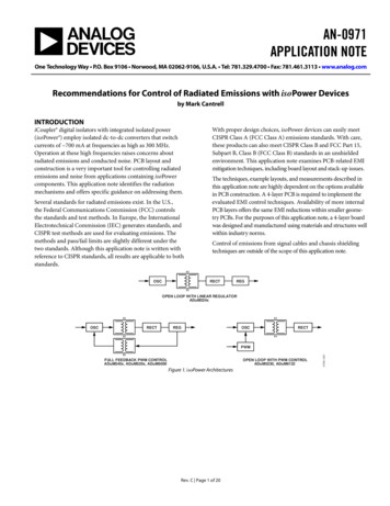
SMART THERMOSTAT 2 Product Manual 76 SMART THERMOSTAT 2 Product ManualINSTALL YOUR NEW THERMOSTATCAUTION: Wiring can vary for each manufacturer.Identify all wiring before removing it from theexisting thermostat.TIP: Take a picture of the wires before you detachthem from the existing thermostat forfuture reference. Disconnect all of the wires and remove the existingthermostat.TIP: Remember to secure the wires so they don’tfall into the wall.Prepare the WiresFollow these guidelines for safe and securewire connections: Ensure the wires are a proper gaugebetween18-24 AWG. Make sure wires have exposed straight endsabout 1/8” long.CAUTION: Verify that the system is 24 VAC. If the oldsystem is labeled as 120 or 240 volts or has wire nuts,the system is high voltage. Do not install the thermostatto a high voltage system. Contact a local HVACprofessional for help.Install the Back PlateWire Your New ThermostatUse the bubble level provided on the back plate as a guide.Mark where the screws will go with a pencil through thescrew holes on the back plate. Ensure the top of theback plate is facing up.Reconnect the wires to the new thermostat.TIP: If necessary, use the trim plate to cover up anymarks or holes left from the old thermostat. Attach thetrim plate before securing the back plate to the wall.TIP: Drill holes with 1/4” drill bit to tap in thedrywall anchors for added support.TIP: If you have extra wires do not install themin the new thermostat. Please contact your localHVAC professional for additional assistance. If you have R, connect it to RH. Z1 or Z2 can be used for W3, H, DH, or EX.NOTE: If you have a 2-wire system (most common)or hydronic heating system, you must add the PowerResistor to the system. Connect this resistor at yourheating equipment between the C and W terminals.
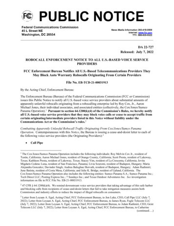
8 SMART THERMOSTAT 2Product ManualSMART THERMOSTAT 2Product Manual 9Terminal DesignationsCONVENTIONAL SYSTEMTerminalDescriptionRCCooling powerRHHeating powerZConfigurable W3, H (humidifier control), DH (dehumidifier control),EX (vent, external air baffle, ERV/HRV )Z2Configurable W3, H (humidifier control), DH (dehumidifier control),EX (vent, external air baffle, ERV/HRV )WHeat stage 1W2Heat stage 2CCommon wire from secondary sid of heating transformer(if 2 transformers)YCool stage 1Y2Cool stage 2GFanOEnergized in Cool modeBEnergized in Heat modeInsert Batteries Into the ThermostatCAUTION: Special Battery Warning Always replace the batteries as soon as you have lowbattery levels, indicated by a caution sign and “LOWBATTERY” flashing on the display. If the batteries drain,the thermostat could leave the HVAC system on or off,overheating or freezing the home. Always replace the batteries when they are low toprotect the thermostat from damage and corrosionby leaking batteries.HEAT PUMPRCCooling powerRHHeating powerZConfigurable W3, H (humidifier control), DH (dehumidifier control),EX (vent, external air baffle, ERV/HRV )Z2Configurable W3, H (humidifier control), DH (dehumidifier control),EX (vent, external air baffle, ERV/HRV )WAux stage 1W2Aux stage 2CCommon wire from secondary side of heating transformer(if 2 transformers)YPump stage 1Y2Pump stage 2GFanOEnergized in Cool modeBEnergized in Heat modeInstall Thermostat Body to Back PlateThe thermostat can be powered by battery or 24 VAC.If a wall transformer is used to power the thermostat,connect between C and RH.Ensure the batteries are installed following the specifiedpolarity markings on the thermostat. If the home is unoccupied for a month or more,such as vacation homes, you should replace thebatteries as a preventive measure against batteryfailure while you are away. Always use new batteries as replacements.Verify that any excess wire is tucked back into the wall to allowroom for the thermostat to sit flush against the back plate.Return the thermostat to the wall plate by pressing the thermostatbody firmly into the back plate mounted to the wall. Ensure thatthe pins on the body are correctly aligned with the back plate.Failure to do so could cause damage to the thermostat.
SMART THERMOSTAT 2 Product Manual 1110 SMART THERMOSTAT 2 Product ManualTHERMOSTAT SETUPTurn the Power On Thermostat will automatically detect the connected wires.Fan on During HeatingZ1/Z2 Terminal FunctionRestore power to all the heating and cooling systems.This can be done at the circuit breaker. Follow the on-screen instructions to complete thethermostat configuration.Tells the thermostat whether the fan should be on duringa heating cycle.These are the “dynamic” terminals. If an auxiliary wire hasbeen connected, please specify the function it will perform.NOTE: If the thermostat screen does not show all theconnected wires, remove the thermostat from the walland verify that all wires are properly connected. If issuespersist, there may be an HVAC problem. Please contactan HVAC service provider for assistance.Depending on the system type and configuration, thethermostat may request the following informationduring setup: Forced Air Heating - Yes W3 - Third stage of heat or aux Radiant Floor Heating - No H - Humidifier Fossil/Electric Baseboard Heating - No DH - Dehumidifier Radiators - No EX - Vent (external air baffle) If Unsure - Not sureBackup Heat TypeTells the thermostat what type of auxiliary/backup heatingthe heat pump uses. Electric - This is the most common type ofbackup heating. Dual Fuel - Some heat pumps use a fossil furnace(for example, natural gas, oil, or propane)or backup heating. If Unsure - The system will automatically detectwhich heat type is appropriate for your system.
SMART THERMOSTAT 2 Product Manual 1312 SMART THERMOSTAT 2 Product ManualConnect the Thermostat to the System5. Select NETWORK6. Select ADD7. Log in to your online account to sync the thermostatwith the account, or contact your Service Provider forinstallation setup.Write your login information below once youhave chosen a personal password.User ID:Password:1. Put the thermostat in OFF mode.2. Put the Z-Wave controller into ADD mode. Refer to thecontroller documentation for more information.3. Press the MENU4. Select SETTINGSbuttonCONFIGURE THE SYSTEMCHECK THE SYSTEMWhile the default settings online will be sufficient inmost cases, you also have the option to change advancedconfiguration settings, such as: Swing, Differential,Recovery Setting, Fan Circulation Period and Duty Cycle,Maximum Setpoints, Minimum Setpoints andThermostat Lock.WARNING: Do not test the AC during cold weather orheat during hot weather. Wait for mild weather tofully test the system.To Check HeatingWARNING: Use caution when changing advancedconfiguration settings. These configuration settingsshould only be changed by those familiar with heatingand cooling systems’ parameters. Contact a localHVAC professional for help.1. Press the MENUbutton to select and useUP/DOWN to scroll to MODE. Press SELECT to choosethe mode option. Use UP/DOWN to scroll to HEAT.Press SELECT to choose the HEAT option.2. Press the UPbutton to raise the setpointabove room temperature.3. Wait 5 minutes for the system to turn on.4. After verifying the heating system is working,return the setpoint to the desired temperature.
SMART THERMOSTAT 2 Product Manual 1514 SMART THERMOSTAT 2 Product ManualCHANGING THE BATTERIESOPERATIONTo Check Cooling1. Press the MENUChanging the Mode and Setpointbutton to select COOL mode.1. Press the MENU2. Press the DOWNbutton to lower the setpointbelow room temperature.2. Press SELECTbutton to access the menu screen.on the MODE option. The modes are HEAT, COOL, AUTO, EMER and OFF.3. Wait 5 minutes for the system to turn on. EMER mode is available for Heat Pump systems.4. After verifying the cooling system is working,return the setpoint to the desired temperature. When in EMER mode, the display will read EMER whenthe thermostat wakes up and the HEAT icon will bedisplayed. Changing the mode will leave EMER mode.3. Press SELECTDisplayWaking the Device1. Press any button to wake the thermostat up.2. After waking, the display will show the current mode,room temperature, and setpoint.on the desired mode.4. Once in the desired mode, press the UPbutton to adjust to the desired setpoint.or DOWN In AUTO mode when the system is idle, the screen willdisplay AUTO. The thermostat will display HEATING whencalling for heat and COOLING when calling for cool.If the thermostat batteries are low, replace the batterieswith two new AAA batteries.1. Remove the thermostat from the back plate by pullingthe thermostat straight out and off the wall.2. Take out the existing batteries.3. Insert the new batteries following the specified polaritymarkings on the thermostat.4. Return the thermostat to the wall plate by pressing thethermostat body firmly into the back plate mountedto the wall. Ensure that the pins on the body are correctlyaligned with the back plate. Failure to do so could causedamage to the thermostat.
SMART THERMOSTAT 2 Product Manual 1716 SMART THERMOSTAT 2 Product ManualNOTICESTROUBLESHOOTINGHeating or Cooling Doesn’t Turn On When the Setpoint isAbove or Below the Room TemperatureTo prevent damaging the compressor, the thermostat insertsa delay when cycling the compressor. If you think the systemshould be on and it’s not, then change the setpoint to be2 degrees beyond the current setpoint and wait 5 minutesto see if the system turns on. If not, contact a localHVAC professional.Heat Pump is “Cooling When it Should be Heating” or“Heating When it Should be Cooling”FCCAccessing the INSTALLER (Setup) MenuThe initial setup menu can be accessed at any time:1. Press the MENUbuttonThis device complies with part 15 of the FCC Rules Operation is subject to thefollowing two conditions:1. This device may not cause harmful interference.–and–2. This device must accept any interference received, including interferencethat may cause undesired operation.2. Select SETTINGS3. Select INSTALLExclude the Thermostat From the Z-Wave NetworkIf for some reason the thermostat must be excludedfrom the network, follow the steps below to do so.Some heat pumps use the O terminal, while others use the Bterminal. Try switching the O or B wire to the opposite terminal.Contact a local HVAC professional for further assistance.1. Set the thermostat to OFF mode.Thermostat Buttons Flash Red and ScreenWill Not Illuminate2. Put the Z-Wave controller into Delete mode. Refer tothe controller documentation formore information.The batteries in your thermostat are extremely low. Replacethe batteries with fresh batteries immediately.3. Press the MENUbuttonThis equipment has been tested and found to comply with the limitsfor a Class B digital device, pursuant to part 15 of the FCC Rules. Theselimits are designed to provide reasonable protection against harmfulinterference in a residential installation. This equipment generates, usesand can radiate radio frequency energy and, if not installed and used inaccordance with the instructions, may cause harmful interference to radiocommunications. However, there is no guarantee that interference willnot occur in a particular installation. If this equipment does cause harmfulinterference to radio or television reception, which can be determined byturning the equipment off and on, the user is encouraged to try to correctthe interference by one or more of the following measures: Reorient or relocate the receiving antenna. Increase the separation between the equipment and receiver. Connect the equipment into an outlet on a circuit different from that towhich the receiver is connected.ICThis device complies with Industry Canada licence-exempt RSS standard(s). Operation issubject to the following two conditions: (1) this device may not cause interference, and (2) thisdevice must accept any interference, including interference that may cause undesired operationof the device.Le présent appareil est conforme aux CNR d'Industrie Canada applicables aux appareils radioexempts de licence. L'exploitation est autorisée aux deux conditions suivantes : (1) l'appareil nedoit pas produire de brouillage, et (2) l'utilisateur de l'appareil doit accepter tout brouillageradioélectrique subi, même si le brouillage est susceptible d'en compromettre le fonctionnement.The device has been evaluated to meet general RF exposure requirement. To maintaincompliance with RSS-102 — Radio Frequency (RF) Exposure guidelines, this equipment shouldbe installed and operated with a minimum distance of 20cm between the radiator and your body.le dispositif de a été évalué à répondre général rf exposition exigence.pour maintenir laconformité avec les directives d'exposition du RSS-102-Radio Fréquence (RF). ce matériel doitêtre installé et exploité à une distance minimale de 20 cm entre le radiateur et votre corps.Note: The grantee is not responsible forany changes or modifications not expresslyapproved by the party responsible forcompliance. Such modifications could voidthe user’s authority to operate the equipment. Consult the dealer or an experienced radio/TV technician for help.4. Select SETTINGS5. Select NETWORK6. Select REMOVE. Follow the on-screen instructions.The device has been evaluated to meet general RF exposure requirement.To maintain compliance with FCC's RF exposure guidelines, the distance must be atleast 20 cm between the radiator and your body, and fully supported by the operatingand installation configurations of the transmitter and its antenna(s).For more help, contact yourService Provider.
www.Alarm.com 2018 Alarm.com. All rights reserved. Designed in the USA by Building 36, an Alarm.com company.180724 v2.0
14 SMART THERMOSTAT 2 Product Manual SMART THERMOSTAT 2 Product Manual 15 If the thermostat batteries are low, replace the batteries with two new AAA batteries. 1. Remove the thermostat from the back plate by pulling the thermostat straight out and off the wall. 2. 3. 1. 2. 1. HEAT, , , EMEROFF. or