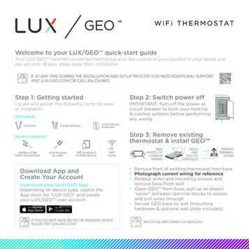
Transcription
Thermostat Installation Best PracticesIf this is to replace an existing thermostat, just use the existing thermostat location.If this is a new install follow these suggestions: Locate the thermostat about 5 ft. above the floor away from direct sunlight, lamps, radios,televisions, fireplaces, hot water pipes, or other heating or cooling sources. Do not locate the thermostat near doors to the outside or windows. Do not locate the thermostat in a damp area. Do not locate the thermostat in an area that lacks air circulation. Switch OFF the electricity to the HVAC unit. Remove the cover to the existing thermostat Make a note of the terminal location for each wire connected to the thermostat wiringTerminals (use enclosed labels to label wires). Wire colors are not standard so it is importantto note the terminal label each wire is connected to on the existing thermostat. While removing each wire from the existing thermostat wiring terminal, make sure to securethe wire so that it does not fall back into the wall. Once all wires are removed from the existing thermostat wiring terminal, remove the existingthermostat from the wall. Make sure to leave at least 3” of wire for each connection onto the CentraLite thermostatwiring terminal. Remove 1/8” insulation from the end of each wire.1 Page
See Figure-1 “Full Terminal View”2 Page
A thermostat which shows “E0” is a thermostat which has not yet been connected to a“valid” system or one which has not yet been “programmed” yet. This “E0” is anindicator that the thermostat is in a factory default state. This “EO” status can bechanged to a valid status by either programming the thermostat or by hooking up thethermostat to a valid system. (See Appendix-A for programming menu options) By default the CentraLite thermostat comes with a wire jumper connecting the RH andRC power terminals. On most units only one power source is used and can beconnected to both RH and RC. But if you have another type of HVAC system, it mayrequire separate power sources for Heating and Cooling. In this case you will removethe jumper and separately power RC and RH. (See Figure-1) The CentraLite thermostat can be powered by 4 AA batteries or by the power from the24V off the HVAC unit if a Common wire is available. Even if you use the common wirefor power you should still install 4 AA batteries as a backup for the thermostat time clock. Connect the wires to the terminal at the middle of the thermostat Hold the thermostat up to the wall in the desired position. Mark where the 4 holes are tobe drill. Drill 4 3/16 holes for the wall anchors. Use the included wall anchors and screws to mount the thermostat securely onto thewall. Install 4 AA batteries into the battery compartment at the bottom of the thermostat. Snap the top cover or front faceplate onto the thermostat.3 Page
Figure-1 – Full Terminal View From the factory the thermostat comes configured to work with single stage Cool/Heat,Single Speed Fan systems. If your HVAC system is different refer to the programming section to configure thethermostat for your system. If you have separate power for RH and RC then you will need to remove the factoryinstalled jumper between RH and RC.4 Page
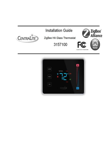
Figure-2 “Thermostat Overview” After completing any necessary configuration make sure the thermostat is in Cool mode bypressing the MODE button until Cool is displayed at the bottom of the screen. (See Figure-3) Make sure the system is not calling for Cooling by setting the setpoint several degrees abovethe room temperature. Then check the Fan operation by pressing the Fan button. Whenthe Fan indicator is illuminated air should blow from the unit. Now make sure the Fan mode is in Auto and run the setpoint temperature at least severaldegrees below the room temperature. Give the thermostat at least 3 minutes to respond. Now change the system mode to Heat. Allow the system at least 3 minutes to respond.5 Page
The Heat (flame) mode symbol should illuminate and system should be blowing hot air.Figure-3 “Thermostat Operation” MODE button cycles between system modes: HEAT/COOL/E-H*/OFF*E/H stands for emergency heat mode – this mode uses second-stage heat as a supplemental or back-up heat. FAN button toggles between Fan On Mode and Fan Auto Mode. HOLD button will enable Hold function which locks out all scheduled system changes. Thisincludes internal schedules and external schedules from a controller only if the controllersupports this. The CentraLite thermostat is intended to operate as part of a ZigBee HA network. The first step in the join process is to make sure the ZigBee HA controller is in a “JoinNetwork Mode” state (This state may vary depending on your ZigBee HA Controller) The CentraLite thermostat will attempt to join a ZigBee HA network upon power up(as long as it has not already been joined to another ZigBee HA network). Upon successfully joining a ZigBee HA network the ZigBee Radio status indicator shouldilluminate. (See Figure-4)Figure-46 Page
If the indicator does not illuminate then make sure the ZigBee HA system controller is“Open” for joining. If the thermostat is part of a network and wish to leave that network and join to adifferent network, then you will go to the Menu and choose the option to leave network(See Appendix-A for menu options) followed by the join network (Appendix-A). Once ajoinable HA network has been located, the ZigBee Radio Icon will appear. If the ZigBee Radio Icon is solid then you are successfully connected to a network. If theicon is blinking slowly then you are currently scanning for a network. If the icon isblinking fast then you are connected to a network but no parent has been found. If theicon quits blinking and does not stay on then the device was unable to find a network tojoin.See Appendix-A of this document for a Quick Start Guide for support technician programmingmode and programming functions.Appendix-A7 Page
Quick Start GuideTechnical Support & InstallationProgramming Mode Menu FunctionsA thermostat which shows “E0” is a thermostat which has not yet been connected to a “valid”system or one which has not yet been “programmed.” This E0 is the factory default state thethermostat was shipped in and can be removed to a valid status by either programming thethermostat or by hooking up the thermostat to a valid systemHow to enter thermostat Programming Mode: Before you enter programming mode to programthe thermostat, the device needs to be in an “off” state. To turn the thermostat off, press the“Mode” button until “Off” appears on the screen. PRESS BETWEEN the hold button and the fan button. Continue to hold and swipedown on the right slider - “01” will displayWhen “01” is displayed, it indicates you are in “programming mode.”Use the and – buttons to advance through the menu options listed below in the “MenuOptions” list.Use the HOLD button to enter a menu option then use the and – to set the appropriatevalue and then HOLD to confirm you menu choice (HOLD is used like the ENTER key)Note, utilizing the MODE button will exit you from the menuWhen finished programming, tap the MODE button until the thermostat to EXIT themenu and returned to normal operation – programming mode has been exited.Technical Support Thermostat Menu FunctionsMenu OptionsDisplay Celsius and Fahrenheit . 10- Celsius1- Fahrenheit (Default)Heat type (Heat pump / Non Heat pump) . 20- Non Heat pump(Default)1- Heat pumpHeat source (Gas / Electric) . 30- Electric1- Gas(Default)Temperature Calibration . 4-2.5 – 2.5 Celsius-4.5 - 4.5 Fahrenheit(Default) - 0Set Minimum Heatpoint . 5(Default) – 44 Fahrenheit, 7 Celsius8 Page
Set Maximum Heatpoint . 6(Default) – 86 Fahrenheit, 30 CelsiusSet Minimum Coolpoint . 7(Default) – 44 Fahrenheit, 7 CelsiusSet Maximum Coolpoint . 8(Default) – 86 Fahrenheit, 30 CelsiusSet Minimum Deadband. 9(Default) – 1.8 Fahrenheit, 1.0 CelsiusSequence of Operation . 100- Cool Only1- Cool with reheat2- Heat Only3- Heat with reheat4- Full Auto5- Full Auto with reheat6- Manual (Default)7- Auto OnlyEZ Mode . 1111- YesAll others - NoJoin Network . 120- No1- YesLeave Network . 1311- YesAll others - NoRejoin Network. 140- No1- YesRedetect System Type . 150- No1- YesTypes Detected04 - HP TWO COOL TWO HEAT05 - TWO COOL TWO HEATFF - INVALID RELAY CONFIGURATIONReset . 160- No1- Yes9 Page
Factory Reset All. 1711- YesAll others - NoDisplay Configuration and Network Settings . 18Order of Display:1- PSOC Version Number2- Ember Version Number3- Heat Type4- Heat Source5- Temperature Calibration6- Relays Detected7- Network State8- Network Channel9-10- PanIDReset Counter . 1901- Reset to 0Standby Brightness Level . 200-99- Brightness percentage levelAppendix-BQuick Start GuideBattery Installation and Replacement1. Pull the wall thermostat housing off of its wall mount plate. If the housing will noteasily pull off, slide the housing up on the wall mount plate and pull it off2. Slide the new batteries, with the plus sign in the direction of the correct polarityindicator on the battery holder and into the slots.3. Set the thermostat housing onto the back wall plate with the pins on the backaligned. Slide the housing down to snap it back into place.10 P a g e
The CentraLite thermostat is intended to operate as part of a ZigBee HA network. The first step in the join process is to make sure the ZigBee HA controller is in a “Join Network Mode” state (This state may vary