Transcription
HVAC AutomationModel 8800 Communicating ThermostatSystem Installation ManualREAD AND SAVE THESE INSTRUCTIONS
COMMUNICATING THERMOSTAT SYSTEM INSTALLATION MANUALThis manual will guide the installer through the installation, wiring and checkout of an Aprilaire Model 8800 Communicating ThermostatSystem. For a complete command set with programming suggestions, see the programming manual (Part No. 10009414). Please visitwww.aprilairepartners.com/docs/literature for this document.TABLE OF CONTENTSCollect the components needed . . . . . . . . . . . . . . . . . . . . . . . . . . . . . . . . . . . . . . . . . . . . . . . . . . . . . . . . . . . . . . . . . . . . . . . . . . . . . . . . . . . . . . . . . . . 3Disconnect power to all HVAC equipment and/or zone control panels . . . . . . . . . . . . . . . . . . . . . . . . . . . . . . . . . . . . . . . . . . . . . . . . . . . . . . . . . . . . . 4Run the required wires and mount the system components . . . . . . . . . . . . . . . . . . . . . . . . . . . . . . . . . . . . . . . . . . . . . . . . . . . . . . . . . . . . . . . . . . . . . 5Connect the control wires to the HVAC/zone system and thermostats . . . . . . . . . . . . . . . . . . . . . . . . . . . . . . . . . . . . . . . . . . . . . . . . . . . . . . . . . . . . . 7Connect the communication and power wires to the distribution panel and thermostat . . . . . . . . . . . . . . . . . . . . . . . . . . . . . . . . . . . . . . . . . . . . . . . 8Connect multiple distribution panels . . . . . . . . . . . . . . . . . . . . . . . . . . . . . . . . . . . . . . . . . . . . . . . . . . . . . . . . . . . . . . . . . . . . . . . . . . . . . . . . . . . . . . . . 9Connect protocol adapter to the distribution panel and host computer or automation system . . . . . . . . . . . . . . . . . . . . . . . . . . . . . . . . . . . . . . . . . 10Check-out HVAC system operation . . . . . . . . . . . . . . . . . . . . . . . . . . . . . . . . . . . . . . . . . . . . . . . . . . . . . . . . . . . . . . . . . . . . . . . . . . . . . . . . . . . . . . . . 11Set thermostat address and total number of thermostats . . . . . . . . . . . . . . . . . . . . . . . . . . . . . . . . . . . . . . . . . . . . . . . . . . . . . . . . . . . . . . . . . . . . . . 11Setup computer for communication system checkout . . . . . . . . . . . . . . . . . . . . . . . . . . . . . . . . . . . . . . . . . . . . . . . . . . . . . . . . . . . . . . . . . . . . . . . . . . 12Check-out communications to the thermostat network . . . . . . . . . . . . . . . . . . . . . . . . . . . . . . . . . . . . . . . . . . . . . . . . . . . . . . . . . . . . . . . . . . . . . . . . . 15Appendix 1 – Special considerations for installing the Model 8800 with the 8870 Series Communicating Thermostat . . . . . . . . . . . . . . . . . . . . . . 16Appendix 2 – Sensor averaging . . . . . . . . . . . . . . . . . . . . . . . . . . . . . . . . . . . . . . . . . . . . . . . . . . . . . . . . . . . . . . . . . . . . . . . . . . . . . . . . . . . . . . . . . . . . 17WARNING1. 1 20 volts may cause serious injury from electrical shock. Disconnect electrical power to the HVAC system before startinginstallation. This system is a low-voltage system.2. Improper installation may cause serious injury from electrical shock. This system must be installed by a qualified contractor inaccordance with NEC Standards and applicable local and state codes.2
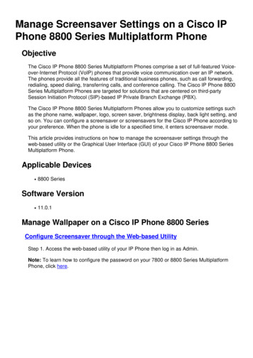
COLLECT THE COMPONENTS NEEDEDTools neeDEDWire neeDED Small flat head screwdriver for terminal screws (1/8” wide tip). Multi-conductor thermostat cable (18–20 gauge). Medium size flat/phillips head screwdriver for component mountingscrews. Category 5 communication wire (4 pair twisted cable). Volt/ohm meter. Computer with available com port (RS-232) and terminal emulatorsuch as HyperTerminal (for system checkout). Wire strippers. Small level (use to mount components level, required forappearance only).SYSTEM COMPONENTSModel 8819 Distribution PanelModel 8800Communicating ThermostatThe Model 8800 thermostat is anRS-485 communicating thermostat,configurable for single and multi-stageheat/cool or heat pump systems. It isalso configurable as a whole homehumidifier/dehumidifier control.The distribution panel is a switch controlledcommunication bus that can be wired toeight Model 8800 thermostats. This allowsthermostat communication to be turned onand off at one convenient location whichsimplifies installation and troubleshooting.RS-485/422DC 9VTXDRXDPOWERModel 8811 Protocol AdapterAutomation System ControllerThe 8811 protocol adapter is used toconvert an RS-485 communication signalto an RS-232 signal that is readable by ahost computer’s serial port.RS-232 or RS-485 based automation systemcontroller such as the Aprilaire SystemController.RS-232Model 8081 and 8082 Support Modules (Optional)Support modules can be added if you require additional temperature or humidity values. Support modules can also be used for sensor averagingin large areas.Model 8081 Support ModuleModel 8082 Support ModuleProvides two temperature values. One onboard or remote temperature sensor. One remote temperature sensor.Provides one temperature and one humidityvalue. One onboard humidity sensor. One onboard or remote temperature sensor.WARNINGUse only the correct support module with each thermostat. Damage will occur if they are mixed.8800s use only 8081 & 8082 support modules. 8870s use only 8061 & 8062 support modules.3
Model 8051, 8052 and 8053 Remote Temperature Sensors (Optional)These sensors can be used directly with the Model 8800 thermostat or with support modules.Model 8051 Flush Mount SensorModel 8052 Outdoor Temperature SensorModel 8053 Wall Mount SensorFOR EASE OF INSTALLATION AND TROUBLESHOOTING DO THE FOLLOWING: Use Category-5 cable for all communication wiring. Check and recheck to ensure connection to the proper terminals before powering up the thermostats. Use wire color as a guide and be consistent. Use a Distribution Panel on all systems with more than one zone to simplify wiring and troubleshooting.DISCONNECT POWER TO ALL HVAC EQUIPMENT AND/OR ZONE CONTROL PANELS If the thermostats are wired to a zone control panel, there is generally one set of input terminals supplying power to the thermostats anddampers. This must be disconnected. If the thermostats are wired directly to HVAC equipment, the power must be shut off at the equipment. This can generally be accomplished byturning off the disconnect switch located near the equipment. If an obvious disconnect switch is unavailable, you will need to turn the circuitoff using the fuse or circuit breaker. Remove the fuse or shut down the circuit breaker serving the equipment.CAUTIONFailure to disconnect power could result in damage to the HVAC equipment or thermostats. Leave power disconnected until all otherelectrical connections have been made and checked for accuracy.4
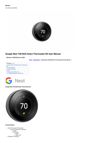
RUN THE REQUIRED WIRES and Mount the System Components1. Determine component locations.2. Run and label wires. Use FIGURE 1 for selecting wire type.3. Mount components as specified in each product’s installation instructions.Figure 1 – Run Wire for SystemStraight through serial cableprovided with Protocol AdapterCategory 5 (4 pair twisted)communication wireModel 8052Outdoor Temperature SensorHumidifierCommunicating HumidistatThermostat cableZone DampersDistribution PanelCommunicating ThermostatAutomationSystemRS-485/422DC 9VTXDRXDPOWERZone Comfort Control PanelHVAC SystemRS-232Protocol Adapter(if needed)Support Module24VACCRModel 802924VAC Plug-inTransformerSupport ModuleModel 8051Flush Mount SensorMaximum Wiring DistancesFromToMaximum DistanceAutomation or Computer SystemProtocol Adapter3 ft. Cable Provided with Protocol AdapterProtocol AdapterThermostat (this includes going through the Distribution Panel)4000 ft. (cumulative)ThermostatSupport Module1000 ft. (cumulative)Support ModuleTemperature Sensor Option300 ft.ThermostatTemperature Sensor Option300 ft.5
Figure 2 – Network Interconnection WorksheetFill Out and Leave with System Software PackageJOB TITLE:JOB ONADDRESSDISTRIBUTION PANEL LOCATION / ETO DISTRIBUTION PANELLOCATIONADDRESS6LOCATIONADDRESS
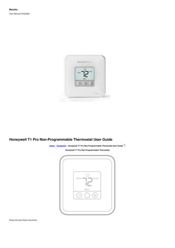
CONNECT THE CONTROL WIRES TO THE HVAC/ZONE SYSTEM AND THERMOSTATSA qualified HVAC technician should performthis step to ensure proper termination.Figure 3 – Conventional Heat /Cool1. Make sure the HVAC system power is off.THERMOSTAT IS POWEREDFROM 8819 OR 24VACTRANSFORMERSingle transformer(use Jumper wire)DO NOT TURN ON THE HVACSYSTEM POWER YET!REMOTE TEMPSENSOROUTDOOR TEMPSENSOR1st HEATING2nd HEATINGJUMPERFAN1st COOLINGNOT USEDCOMMUNICATIONTERMINALSNOT USEDRefer to the thermostat installation manualfor check-out procedure and other wiringdetails2nd COOLINGTRANSFORMER2. The Thermostat Installation Instructionsshow wiring diagrams for several differentHVAC equipment types. Use FIGURES3-5 as a reference only. Use color codingwhere possible.SUPPORTMODULEB A B- A- C B O Y Y2 G RC RH W2 W R S2 S1 T1 T2 RSB RSAFigure 4 – Heat PumpOUTDOOR TEMPSENSOR1st AUX HEATING2nd AUX HEATINGHEAT PUMPTRANSFORMERJUMPERFAN2nd COMPRESSOR1st COMPRESSORCOMMUNICATIONTERMINALSREVERSING VALVENOTE: “O” is activein cooling and “B” isactive in heating.REMOTE TEMPSENSORTHERMOSTAT IS POWEREDFROM 8819 OR 24VACTRANSFORMERSingle transformer(use Jumper wire)SUPPORTMODULEORB A B- A- C B O Y Y2 G RC RH W2 W R S2 S1 T1 T2 RSB RSAFigure 5 – HumidistatDRY CONTACTPOWERED CONTACTB A B- A- C B O Y Y2 G RC RH W2 W R S2 S1 T1 T2 RSB RMERCOMMUNICATIONTERMINALSTHERMOSTAT IS POWEREDFROM 8819 OR 24VACTRANSFORMERHUMIDIFIERDEHUMIDIFIERTHERMOSTAT IS POWEREDFROM 8819 OR 24VACTRANSFORMERSUPPORTMODULEB A B- A- C B O Y Y2 G RC RH W2 W R S2 S1 T1 T2 RSB RSA7
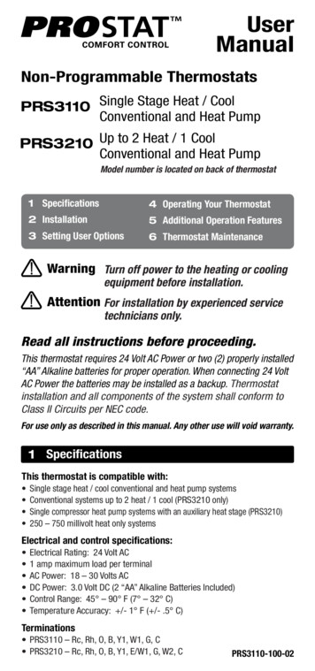
CONNECT THE COMMUNICATION AND POWER WIRES TO THE DISTRIBUTION PANELAND THERMOSTAT1. MAKE SURE THAT ALL SWITCHES ON THE DISTRIBUTION PANEL ARE OFF!2. Connect the communication wires. FIGURE 6 shows how each thermostat is to be wired to the distribution panel. Use the wire colors shown in FIGURE 6 to help ensure proper, consistent connections.3. Use a Model 8029 24VAC transformer or equivalent to power each distribution panel.Figure 6 – System Communication WiringBLU/WHTBLUORGA- A B B-ORG/WHTMODEL NGRN/WHTGRN/WHTORG/WHTORGB A B- A- CAA A- B B-BLU/WHTBLURCMODEL 8819DISTRIBUTION PANELBOY Y2 G RC RH W2 W R S2 S1 T1 T2 RSB RSAMODEL 8800 THERMOSTATCAT-5BLU/WHTBLUORGORG/WHTCAT-5DO NOTCONNECTT1A A- B B- R CON OFFOFF ONON OFFOFF ONBBGRNBLU/WHTGRN/WHTBOY Y2 G RC RH W2 W R S2 S1 T1 T2 RSB RSAMODEL 8800 THERMOSTATBLUMODEL WHTRMODEL 8029 24VACPLUG-IN TRANSFORMER8B A B- A- CORG/WHT24VACCORGBLUORGCAT-5B- B A- A CAAROFF ONON OFFCBBB- B A- A OFF ONON OFFGRNGRN/WHTRA A- B B- R CAABLUBLU/WHTCBOFF ONB- B A- A ON OFFMODEL 8051FLUSH MOUNTSENSORORGORG/WHTRBOFF ONCON OFFSPARE FUSEA A- B B- R CAAORG/WHTT4ROFF ONMODEL8081 OR 8082SUPPORTMODULET3BLU/WHTBON OFFT2B- B A- A OFF ONBFUSEA A- B B- R CAON OFFRSBRSABACB A B- A- CBOY Y2 G RC RH W2 W R S2 S1 T1 T2 RSB RSAMODEL 8800 THERMOSTATMODEL 8051FLUSH MOUNTSENSOR
CONNECT MULTIPLE DISTRIBUTION PANELS1. MAKE SURE THAT ALL SWITCHES ON THE DISTRIBUTION PANELS ARE OFF!2. If more than one Distribution Panel is used in the thermostat network, the communication lines must be daisy-chained together. Use the wire colors shown in FIGURE 7 to help ensure proper, consistent connections.3. Power each distribution panel with a separate Model 8029 24VAC transformer or equivalent 40VA 24VAC transformer.Figure 7 – Multiple Distribution PanelsA- A B BCAT-5DO NOTCONNECTAAA A- B B-OFF ONPWRC24VACAON OFFOFF ONBPWRBON OFFOFF ONPWRB- B A- A ACBON OFFRPWRCOFF ONBCAON OFFA A- B B- RA A- B B- RABB- B A- A BRA A- B HTORGORG/WHTCAT-524VACCRCMODEL 8029 24VACPLUG-IN TRANSFORMERRMODEL 8029 24VACPLUG-IN TRANSFORMER9
CONNECT PROTOCOL ADAPTER TO THE DISTRIBUTION PANEL AND HOST COMPUTEROR AUTOMATION SYSTEM1. MAKE SURE THAT ALL SWITCHES ON THE DISTRIBUTION PANEL ARE OFF!2. Use Category-5 wire to connect the main communication terminals on the Distribution Panel to the “Breakout Adapter” of the protocol adapter(see FIGURE 8).3. Connect the RS-232 cable from the protocol adapter to the computer or automation system. A 3 ft. RS-232 cable is provided. Some computers use 25-pin connectors on serial ports, which requires a DB25 connector. A DB9 connector fits a 9-pin port. DB9 to DB25transitions are available at most computer retail stores.4. Power up the Protocol Adapter with the plug-in transformer provided. The “Power” LED on the Protocol Adapter should light up when power isapplied.Figure 8 – Protocol Adapter WiringCAT-5 NETWORK CABLE (NOT PROVIDED)BLU/WHTBLUEORANGEORG/WHT9VDC 500mAAC PLUG-INTRANSFORMER(PROVIDED)DO NOTCONNECTB- B A A-A-A B B-RS-485/422 BREAKOUTADAPTER (PROVIDED)A A- B B-APRILAIRE MODEL 8819DISTRIBUTION PANELOR MODEL 8800COMMUNICATINGTHERMOSTATRS-485/422DC 9VCOMPUTER OR AUTOMATIONSYSTEM WITH RS232 SERIALCOMMUNICATION PORT(NOT PROVIDED)RS-485/422DC 9VPIN #1TXDRXDPOWERDB9 RS-485 /422 CONNECTOR PIN-OUTPIN #RS-485/422RS-232RS-232 3FT CABLE(PROVIDED)STRAIGHT THROUGH10123456789A- A B BGND NC 9V NC NCTx- Tx Rx Rx-
CHECK-OUT HVAC SYSTEM OPERATIONUse the thermostat to verify that the equipment is being controlled. A checkout procedure is supplied in the installation instructions with thethermostat. This procedure will verify only that the thermostat operates the equipment. Communication system checkout will be performed next.Set thermostat address and total number of thermostatsIMPORTANT!THESE STEPS MUST BE DONE AT EACH THERMOSTAT FOR COMMUNICATION TO WORK PROPERLY.1. Enter the thermostat’s Installer Setup Menu. Press [MODE] to set system to OFF.Figure 9 Press [MENU] to enter main menu. ress and hold [SETUP] for seven seconds, [INSTALL INGOPTIONS Press [INSTALL SETUP] to enter installer setup menu. Press [NEXT] or [BACK] to page through the settings.2. Select System Setting 00 NETWORK ADDRESS. Press up or down to adjust the setting. Numbering should start at 1 and continue sequentially(64 maximum). No two thermostats should have the same address.3. Select System Setting 01 NUMBER OF NODES and set the totalnumber of thermostats on the network. Press up or down to adjust the setting. This number must be set the same on all thermostats.4. (Optional depending on automation equipment) Select SystemSetting 02 BAUD RATE and set the communication baud rate.Default is 9600.5. Press [DONE] to save and exit, or [CANCEL] to exit withoutsaving. The thermostat will discard changes and exit if nothing is pressedwithin 60 seconds.To reset the installer settings to the default, reset the thermostat bypressing the [RESET] button inside the battery cover.11
SETUP COMPUTER FOR COMMUNICATION SYSTEM CHECKOUTREQUIREMENT: HyperTerminal software and a PC with a serial port or usb to serial port adapter.1. Connect the Protocol Adapter RS-232 output to a computer with Windows ’95, ’98, Windows 2000, Windows NT, or XP.Note: Newer Windows systems may not include HyperTerminal.2. From the Start menu, select PROGRAMS ACCESSORIES COMMUNICATION HYPERTERMINAL. HyperTerminal is a terminalemulator program provided with Windows that will be used to test the communication system.3. Double click the Hypertrm icon. You will then be asked to name the new connection and select an icon. Type in any name you want (theshorter the better) and select the “atom-like” symbol at the end of the Icon list (see FIGURE 10). Then click OK.Figure 10 – New Connection12
4. This will bring up a Connect to dialog box. From the pull downnext to “Connect using:”, select the Com port to which the ProtocolAdapter is connected (see FIGURE 11). Start with Com port 1 (orthe next lowest available number) if you are unsure which one touse. Click OK.Figure 11 – Select Com Port5. A COM1 Properties dialog box should appear. Use the pull-downmenus or type in the following for each selection (see FIGURE 12): Bits per second: 9600 (or 19200 if thermostats are configured forthis baud rate) Data bits: 8 Parity: None Stop bits: 1 Flow control: noneClick OK.Figure 12 – Connection Properties13
6. From the File pull-down menu, select Properties. This will bringup a Properties dialog box.Figure 14 – ASCII Setup7. Select the Settings tab. Make the following selections(see FIGURE 13):Terminal keysCtrl HEmulation: Auto DetectTelnet terminal: ANSIBackscroll buffer lines: 500Figure 13 – Terminal Settings9. Click OK to put away both dialog boxes.10. Verify that you have a connection between the computer andthe Protocol Adapter. Have the Protocol Adapter within eyesightof the computer keyboard. Type any character and confirm thatthe “RXD” LEDs on the Protocol Adapter flash as you type (seeFIGURE 8 on page 10). The LEDs flash very quickly.11. Press Enter to clear the command line.8. Then select the ASCII Setup button. This will bring up an ASCIISetup dialog box. Make the following selections (see FIGURE 14): Echo typed characters locally Append line feeds to incoming line ends Wrap lines that exceed terminal widthNOTE:IF USING AN EXISTING HYPERTERMINAL CONNECTION YOUMAY NEED TO UNCHECK THE “SEND LINE FEEDS ” BOX.14 ote: On Windows ’98 computers, HyperTerminal does not echoNtyped characters (doesn’t show them on the screen as you type)locally. Do not be concerned. This can be a little confusing, butdoes not affect the checkout of the thermostat communicationsystem. If you were unable to verify a connection, specify adifferent com port. Go to the File pull down menu, and selectProperties. Change the “Connect using:” setting to adifferent port by using the pull down menu options. Start typingand look for the Protocol Adapter “RXD” or “TXD” LEDs toflash. Repeat until you have successfully verified connectionbetween the computer and communication system, or until yourun out of com ports to choose from in the “Connect using:”pull down. If there is still no communication you are going tohave to consult a computer professional.
CHECK-OUT COMMUNICATIONS TO THE THERMOSTAT NETWORKThis section confirms communications to each thermostat and each thermostats network address.1. At the distribution panel turn on the communication switches A and B for the thermostat with address#1 (see FIGURE 15).2. At the Hyperterminal program type: SN ID? and press Enter. You should see response:SN1 MODEL# 8800 VER: x.xxx - RPC 2011 (x.xxx represents the current firmware version number) If the response is not exactly as shown, there is a communication signal problem. The most likely sources are a loose terminal connection,incorrect wiring, incorrect wire type, damaged wire, electrical interference or incorrect power supply.3. Now back at the distribution panel turn on the communication switches A and B for the thermostat with address#2.4. At the Hyperterminal program type: SN ID? and press Enter. You should see response from both thermostats:SN1 MODEL# 8800 VER: x.xxx - RPC 2011SN2 MODEL# 8800 VER: x.xxx - RPC 20115. Repeat this process adding one thermostat each time to verify communications to all thermostats. Each time you turn on the communicationswitches and send SN ID? command to a new thermostat, a new “SN” number should respond.6. Once you have successfully completed this procedure you have verified that proper communication exists between the computer and all of thethermostats. To test out all of the functions of the thermostat, use the software or automation package being installed with this system.Figure 15 – Com SwitchesAA A- B B-“A” LED flashes when communicationsare transmitted by the thermostatsBON OFFAOFF ONBOFF ON“B” LED flashes when communicationsare transmitted by the host computer orautomation system.RON OFFCCA A- B B- RAB- B A- A B15
APPENDIX 1 – SPECIAL CONSIDERATIONS FOR INSTALLING THE MODEL 8800 WITHTHE 8870 COMMUNICATING THERMOSTATWARNINGWhen replacing an 8870 Thermostat with the model 8800 Thermostat these additional steps are requiredin order for proper operation.1. The 8800 Thermostat cannot be powered from an 8818 Distribution Panel. The 8800 Thermostat must be powered from aseparate 24VAC transformer.2. The Model 8800 thermostat must be set to non-programmable mode to be used in a 8870/8818 system.3. Replace any 8061 TT Support Modules connected to the thermostat with 8081 TT Support Modules, but in cases where asingle flush mount and/or outdoor sensor is used they can be directly connected to the new 8800 Thermostat and the SupportModule can be eliminated.4. Replace any 8062 TrH Support Modules connected to the thermostat with 8082 TrH Support Modules.Figure 16RCCRSBMODEL 802924VAC PLUG-INTRANSFORMERRSAT1T2T3T4MODEL 8081 OR 8082 SUPPORT WHTBLUCAT-5MODEL 8818 DISTRIBUTION PANELB A B- A- CA A- B B-BOY Y2 G RC RH W2 W R S2 S1 T1 T2 RSB RSAAREFOFF ONBON OFFPWROFF ONMODEL 8800 THERMOSTATBBOFF ONON OFFPWRPWRCCFUSEA A- B B- RAOFF ONA A- B B- RAON OFFOFF ONON OFFOFF ONBBPWRMODEL 8061 OR 8062 SUPPORT MODULEORG/WHTBLUBLU/WHTDO NOT CONNECTTO SCRSBRSAT1T2T3T4ORGGRNAPWRB- B A- A CAON OFFBRNCPWRRPWRBOFF ONB- B A- A ON OFFGRN/WHTBRN/WHTRBOFF ONB- B A- A AON OFFSPARE FUSEA A- B B- RAGRNCAT-5RCCPWRRAON OFFBCA A- B B- RAB- B A- A BCRRSRRSCRSBRSAREFRCRHBB AA R.V.-Heat (B)R.V.-Cool (O)GHUM W1DEH Y1W2Y2MODEL 8870 THERMOSTAT
APPENDIX 2 – SENSOR AVERAGINGThis is an option for sensor averaging that does not require support modules. This option can only be used with a specific number of sensors(4 or 9).Figure 17MODEL 8800 THERMOSTATRRB A B- A- C B O Y Y2 G RC RH W2 W R S2 S1 T1 T2 RSB RSAWWWRRWRR WRRWWWS1S2S3S42-WIRETHERMOSTAT CABLE(R RED, W WHITE)FOUR SENSOR TEMPERATURE AVERAGING – WIRINGT1WIRING SHOWN USING MODEL 8051 FLUSH MOUNT SENSORS.SAME WIRING FOR MODEL 8053 SURFACE MOUNT SENSORS.90-1585T2FOUR SENSOR TEMPERATURE AVERAGING – SCHEMATICMODEL 8800 THERMOSTATRRRWWRWB A B- A- C B O Y Y2 G RC RH W2 W R S2 S1 T1 T2 RSB RSAWWRRRWWRWRR W2-WIRETHERMOSTAT CABLE(R RED, W WHITE)RWRWWRWS1S2S3S4S5S6T1T2RWRRWWRRWS7S8S9WNINE SENSOR TEMPERATURE AVERAGING – WIRING90-1584WIRING SHOWN USING MODEL 8051 FLUSH MOUNT SENSORS.SAME WIRING FOR MODEL 8053 SURFACE MOUNT SENSORS.NINE SENSOR TEMPERATURE AVERAGING – SCHEMATIC17
P.O. Box 1467 Madison, WI 53701-1467 Phone: 800/334-6011 Fax: 608/257-4357 www.aprilairepartners.com10009416 1.14B2205497DPrinted in U.S.A. 2014 Aprilaire – A division of Research Products Corporation
Multi-conductor thermostat cable (18-20 gauge). Category 5 communication wire (4 pair twisted cable). WIRE NEEDED Model 8800 Communicating Thermostat The Model 8800 thermostat is an RS-485 communicating thermostat, configurable for single and multi-stage heat/cool or heat pump systems. It is also configurable as a whole home