Transcription
NDJ-5S/NDJ-8S SERIESDIGITAL DISPLAY VISCOMETEROPERATION MANUAL
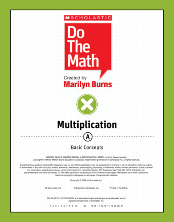
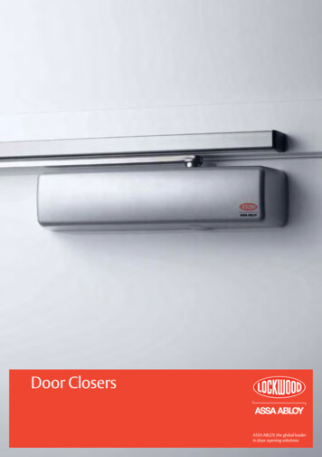
NDJ-5S/8S VISCOMETERresistance of fluid, there will be a torque at the hairspring.PREFACENDJ types digital display viscometer is an upgradedversion of our rotary viscosimeter. This instrument adopts theadvanced mechanical design, manufacturing technology andmicrocomputer control technology, data acquisition right;Display with blue backlight, high brightness LED display, datashowed clearly.This instrument has high sensitivity and reliable testresults, the use of easy to operate, modelling elegantappearance and other characteristics, is used to measure theabsolute viscosity of Newtonian liquid and apparent viscosityof non-Newtonian fluid of the ideal instrument, can be widelyused in oil, paints, plastics, medicine, food, paint, detergentetc, all kinds of fluid viscosity measurement.The instrument is equipped with optional RS-232,temperature sensor, printer interface functions. After matchingwith the PC cable and installation CD, can according to needto record all test data; Equipped with temperature sensors canbe measured the temperature of the liquid; Equipped withmicro printer can print test results directly.After it is balanced against the viscous resistance, thephotoelectric conversion device can convert the information ofthe relative balancing position between the two sensor chipsinto the signals which can be recognized by the computer. Atlast the results of the viscosity of the fluid will be displayedafter being processed by the computer.This instrument adopts microcomputer technology caneasily set range (rotor rotational speed), to digital processingof sensor detected data, and in clearly showed on the screenwhen measuring the set number of rotor, rotational speed, theviscosity of the liquid being measured value and full scalepercentage, etc.The instrument standard with 4 kinds of rotors (1, 2, 3, 4).NDJ-5S four gear speed (6, 12, 30, 60, revolutions perminute), which composed of 16 kinds of combination, canmeasure the determination of the viscosity of the liquid withinTHE MAIN TECHNICAL PARAMETERSthe range of values.NDJ-8S eight gear speed (0.3, 0.6, 1.5, 3, 6, 12, 30, 60,ModelNDJ-5SNDJ-8Srevolutions per minute), which composed of 32 kinds ofRange1 100000mPa.s1 2000000mPa.scombination, can measure the determination of the viscosity#1, #2, #3, #4 (standard),Optional #0 for below 0.1 10mPa.s0.3; 0.6; 1.5; 3; 6; 12;Rotor Speed6;12;30;60r/minAutomaticAutomatically selecting proper rotor andselectionspeedStabilityreading cursorblockMeasuringprecisionof the liquid within the range of values.30; 60r/minCONSTRUCTION AND INSTALLATIONI. The structure of the instrumentThe structure of the instrument is shown in figure :when vertical cursor block is full, 期:2013年 7年 15年data is in stable displayRS-232年 年 年Rotors27年年年机头连接杆 2% (Newton liquid)8Power supplyAC 100 240V; 50/60HzWorkingTemperature 5 C to 35 C , RelativelyconditionHumidity less than 80%Dimensions:370 325 280 (mm)Net Weight:6.8Kg3年年年5年年年49Figure 1(1)Top Bubble Level(2)LCD Screen(3)protective sheathMAIN TECHNICAL PARAMETERSThe synchronous motor drives the sensor chip of the(4)Protection rack for rotor(5)support stand(6)operatingpanel (7)rotor connector (8)rotor(9)Leveling adjustment screwmotor with stable speed, and drives the sensor chip ofII. The installation of the instrumenthairspring, shaft and rotor which connected to it through1. Check the power supply to meet up the instrumenthairspring. If there is no resistance of the fluid, the display willrequirements with reliable ground leadbe at "0" position and the two sensor chips will rotate at same2. Put the instrument on the table without corrosive gaseousspeed. On the opposite, if the rotor is subjected to the viscousfluid, strong electromagnetic interference and vibration g
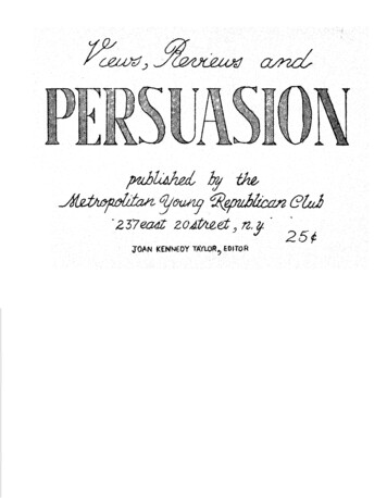
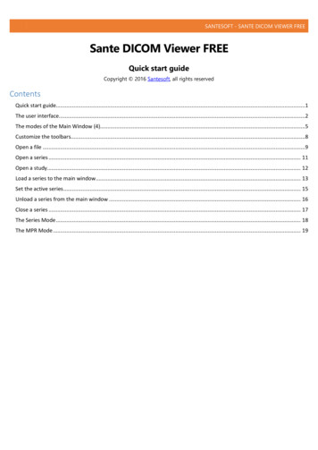
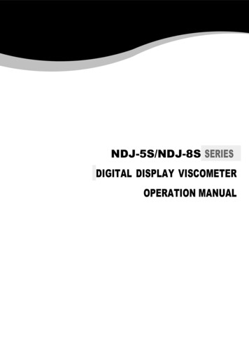
NDJ-5S/8S VISCOMETER2113546Figure 2(1)elevation adjusting screw(with inner hexagonal wrench)(2)fixing hole for head of machine (3)faxing knob ofmachine(4)fixing nut to column(5)elevation knob (6)upright columnOPERATION AND USE OF THE INSTRUMENT1. the measured liquid, ready to put the measured liquid isnot less than 60 mm in diameter, height not less than 120 mmbeaker or straight cylindrical container.2. Accurately control the temperature of the liquid to betested.3. On the rotor protection, after carefully adjust the level ofthe instrument, check the equipment level of the bubble iscentered, ensure instrument in the level of work state.4. Reference range table, select the adaptation of rotorscrewing in rotor connecting head (overlooking, clockwise tomount; counterclockwise to remove).5. Slowly adjust elevator knob, adjust the rotor in themeasured liquid level, until the surface of the rotor grooves(center) and h flat.6. use 0 rotor and lowviscosityfluidtestaccessories according tothe following steps (seefigure 4):support stand with the teethed side facing the back of the(1) Bottom sleeve(2)Fixing screw to sheath(3) Connector for rotorsupport stand. Tighten the nut with wrench to prevent the(4) Connecting nutcolumn rotating (figure,2)(5) Number # 0 rotor3. Screw the column into the hole at the rear of the4. Turn the knob of the elevation clamp and check the(6) Fixing sleeveflexibility and self-locking of the elevation clamp. If it is found(7) Fixing screw toto be too loose or too tight, adjust the stop screw on the clampexternal sleevewith a screwdriver. It should be moved up and down freely, but(8) Red level mark ofa little tight is preferable to prevent the viscometer droppingliquiddown after it is installed.(9) V-block5. Remove the yellow protective sheath from the shaft(10) External measuringsleeve(figure,3)6.Adjust the leveling screw to keep the instrument level.15figure 41) to 0 rotor on the rotor connecting screw rod.2) fixed socket set into the bottom of the instrument the noseunder the hood, and socket set screw and tight.3) put outside in test tube (bottom) 20 25ml of liquid to be28tested.4) will try sleeve fixed sleeve and outer barrel screw and tight,736tighten the outside must pay attention to try screwing in thecone end of tube fixed screw barrel within the triangle grooveof the upper (can be observed in the side of the round hole94Figure 3(1)Printer interface(2)The installing hole for head ofmachine (3)Power switch(4)Yellow protective sheath(5)PC interface(6)Power socket (7)Temperature sensorinterface (8)socket for fuse (9)The hole for protective racktest tube triangle groove is located at the center of circularhole).Control the liquid temperature can be tested after beingtested.5) with bottomless, test tube method basic same as above,【in addition to the (3) 】, when the outer cylinder and
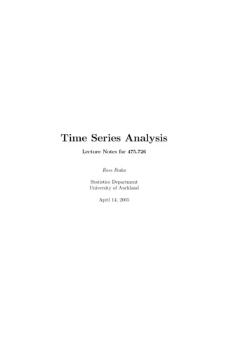
NDJ-5S/8S VISCOMETERrotor immersed in liquid with a fixed sleeve the red dot onthe liquid surface mark.7. Keyboard and display interface description:TIME & DATE1) Instrument keyboard as shown in.DateTime14 -02-13 Thur.09:12:54figure 7BFigure 52) open the power switch at the back of the instrument,into the boot interface, display instrument models:1, communication SettingsCommunication when the cursor is in the "Settings" optionon the Settings, click OK button to enter communicationNDJ-8SW E L C O M ESettings interface, as shown in figure 7 - A set items including14-02-13 Thur. 09:11:52automatically return to the interface, press the RESET buttonprinter, PC communication format, etc., through up and downkeys to move the cursor position, press OK key to set andFigure 6to return to the interface of A directly.2, time Settings3) the system SettingsPress the RESET button to enter the system Settings interface,can communication methods and the system time Settings,press the up and down key to adjust the location of the cursorWhen the cursor is in the "time setting" option on theSettings, press OK button to enter the system time Settingsinterface as shown in figure 7 - B, the left and right keys tomove the cursor to change the selected item, up and downas shown inkeys to change the time according to size, set after press OK tosave these Settings and exit.SYSTEMComnicationTime & DateWhen the machine is in the system Settings interface pressthe RESET button to return to the standby interface.Figure7COMMUNICATIONWrie PrinterThermal PrinterComputerPREPARATIONRotor:1 1#Speed: 6 RPMPress“OK”to confirmFigure 8
NDJ-5S/8S VISCOMETERWORKING18Rotor:1# Speed: 6 RPMData:0. mPa.sPercent: 0.0 %3) press the RESET button, measurement instrument willsuspend measurement; Then you can print measurementresults from the need to press the RESET button, if nokeystrokes, meter will automatically stop at the end of themeasurement. When the test is complete, click OK button toprint the current measured values (such as with a printer) orFi gure 8(A)upload measurement result to the PC. Press the RESET buttonto exit the current measurement, to enter the nextEND18Rotor: 1# Speed: 6 RPMData:0. mPa.sPercent: 0.0 %measurement. Press the RESET button again to return to thestandby interface4) before the measurement, the first to estimate the range theviscosity of the liquid to be measured, then the range in thetable, select the appropriate speed and rotor.Fi gure 8(B)5) when couldn't estimate the measured liquid viscosity,roughly shall be deemed to be high viscosity. Choose fromsmall to large rotor (rotor from high to low) and from slow to4, measurefast speed. High viscosity fluid in principle to choose smallWhen the machine is in standby interface press OK buttonrotor (rotor), slow speed; Low viscosity liquids to choose bigto enter to measure the interface as shown in figure 8: prior torotor (rotor), fast speed. Rotor number engraved on the rotormeasurement of rotor, speed Settings.on the handle.1) rotor set6) instrument with overtravel alarm function, if the measuredCursor in 1 #, according to the Sunday afternoon or keyvalue is greater than 100%, the measured values show is over.choice for rotor, rotor number is five, namely, 1#, 2#, 3#, 4#In order to ensure the accuracy of measurement, the0# and rotor, the default value is 1#.measurement range percentage readings should be controlled2) speed settingbetween 10% 90% is preferred. or button can switch to the rotating speed and position7) in any state, press the RESET button, the program will runthe cursor in 6 RPM position, as shown in figure 8 - A 0.3 RPM.from its starting state, the operating interface to the user toBy Sunday afternoon or key can choose the required speed,select working condition.NDJ-5S speed is divided into five files: 6 RPM, 12 respectivelyTabler/min, 30 r/min, 60 revolutions per minute, and automatic8) rangetransmission. When choose better and speed gear, press OKNDJ-5Skey, the rotor to spin, measure instrument began, screenRange table4display as shown in figure 8 - B.If I do not know the appropriate speed and rotor canrotorchoose automatic transmission after determining the rotor,press OK key, the instrument will automatically startrequired to change the number of rotor.Note: automatic transmission which number to use whenunknown speed rotor, the measurement conditions had better 0500020000100000rangemPa.suse automatic mode.
NDJ-5S/8S VISCOMETERNDJ-8SEND18Rotor: 1# Speed: 6 RPMDate:0. mPa.sPercent: 0.0 %Range 0400000 2000000speed ranger.p.mmPa.sFigure11When the measured value stability after the instrumentwill automatically stop the measure, at this time for reading,printing, such as uploading data operation.operation method 2If you don't know the right speed and rotor, can chooseautomatic transmission., such as: suppose to choose 4 # rotorspeed choice automatic operation method (same as above),and then press OK key, the instrument will automaticallyor display needed to change the number of rotor. Such asdisplay 3 # rotor, then will put 3 # rotor, then press "OK" toOperation methods 1start measuring instrument, finally shows that the viscosity ofIf choose 1 # rotor, 12 turn, after startup, the screen displayas shown in figure 9:NDJ-8SW E L C O M E14-02-13 Thur. 09:11:52search the right speed. The final measurement results showthe liquid to be tested.MATTERS NEEDING ATTENTION1. The instrument set-up strict inspection before they goFigure9out, can work normally after switch on, the operator beforethePress OK key, the screen display as shown in figure 10: thecursor when parked at the 1 # button,PREPARATIONRotor: 1 #Speed: 6 RPMPress“OK”to pecifications, operating in strict accordance with therequirements.2. The instrument must be allowed within the scope of thepower frequency and voltage error measurement, otherwise itwill affect the accuracy of measurement.3. The loading and unloading of the rotor should be carefulFigure10The cursor moves to speed 6 r/min, press Sundayafternoon, again according to 12, as shown in figure 11, andthen press OK key, start measuring instrument.when operating, to connect the instrument of lower headgently lift up after disassembling, do not force too much, don'tmake the rotor lateral force, in order to avoid the damage ofrotor and center pivot. Connection and rotor connected endface and thread head should be kept clean, otherwise willinfluence the correct connection of the rotor and the rotationalstability.4. Mount after the rotor may not be in the case of no liquid"rotate", so as to avoid damage to pivot and bearing.
NDJ-5S/8S VISCOMETER5. Immediately after each use to clean the rotor, whencleaning to remove the rotor, bans on rotor on the instrumentcleaning, rotor shall be properly placed in storage box aftercleaning.ATTACHED TO THE RECORD6. To lift and transport equipment should be screw on silverhead connected to the rotor protective cap.With packing listNote: instrument electricity before work must be under thesilvery white protective cap screw, in order to prevent damagenumber1instrument parts and memory data, don't refill oil on its own.2Suspension, emulsion, polymer, and other liquid viscosity is a3lot of "non Newtonian fluid, its apparent viscosity changes withthe shear rate and time, therefore, under different rotor, rotaryreference (general non-Newtonian fluid should be prescribedDigital displayviscometer host1 4#rotorThe poweradapterstandchooseardand buy1 only 1 set of 1 set of 4Protect the frame1 only 5The base1 only 1 set of 1 this 1 piece speed and time determination, the results are normal. Fornon-Newtonian fluid viscosity value of the measured only as aquantitydesignationto the instrument.7. Do not get optional disassembly and adjustmentName67for determination of the rotor, rotational speed and duration;Rise and fallpillarInstruction foruseCertificate ofor fixed test, determination of environment compared to verify8the condition of its viscosity).9warranty1 piece 1. In order to ensure the precision of test, please note the10Stay wrench1 only following points:111 only 1) to precisely control the temperature of the liquid to betested.2) will the rotor to a long enough time to dip in the measured3) ensure the uniformity of liquid.Allen wrenchheadThe following is optional12liquid constant temperature at the same time, can make it andthe liquid temperature being measured.approval340#rotorRS232cable andCD1 only 1 set of The temperature1 thesensorrootThe micro printer1 4) when measuring the center as far as possible put the rotorin container.Note: design and specifications are change, without prior5) to prevent the rotor immersed in liquid bubbles sticknotice.attached beneath the rotor.6) use protection were determined.7) ensure the cleanness of the rotor.8) operating in strict accordance with the operatinginstructions.9) below 15 mPa. The liquid with 0 s rotor.
NDJ types digital display viscometer is an upgraded version of our rotary viscosimeter. This instrument adopts the advanced mechanical design, manufacturing technology and microcomputer control technology, data acquisition right; Display with blue backlight, high brightness LED display, data showed clearly.