Transcription
INSTALLATIONINSTRUCTIONSE2011 Lennox Industries Inc.Dallas, Texas, USACB(X)26UH( R) Series UnitsAIR HANDLERS505,059M (65937170)07/11Supersedes 05/11Litho U.S.A.Table of ContentsTXVRFCRETAIN THESE INSTRUCTIONSFOR FUTURE REFERENCEWARNINGImproper installation, adjustment, alteration, service ormaintenance can cause property damage, personalinjury or loss of life. Installation and service must beperformed by a qualified installer or service agency.CAUTIONPhysical contact with metal edges and corners whileapplying excessive force or rapid motion can result inpersonal injury. Be aware of, and use caution whenworking near these areas during installation or whileservicing this equipment.Shipping and Packing List . . . . . . . . . . . . . . . . . . . . . .Unit Dimensions . . . . . . . . . . . . . . . . . . . . . . . . . . . . . .CB(X)26UH Series Units . . . . . . . . . . . . . . . . . . . . . . .Requirements . . . . . . . . . . . . . . . . . . . . . . . . . . . . . . . . .Installation Clearances . . . . . . . . . . . . . . . . . . . . . . . . .Installation . . . . . . . . . . . . . . . . . . . . . . . . . . . . . . . . . . . .Condensate Drain . . . . . . . . . . . . . . . . . . . . . . . . . . . . .Duct System and Filters . . . . . . . . . . . . . . . . . . . . . . . .Connecting Refrigerant Lines . . . . . . . . . . . . . . . . . . .Sealing the Unit . . . . . . . . . . . . . . . . . . . . . . . . . . . . . . .Electrical Connections . . . . . . . . . . . . . . . . . . . . . . . . .Airflow Cooling Blower Speed . . . . . . . . . . . . . . . . . .Check Out Procedures . . . . . . . . . . . . . . . . . . . . . . . . .Operation . . . . . . . . . . . . . . . . . . . . . . . . . . . . . . . . . . . .Maintenance . . . . . . . . . . . . . . . . . . . . . . . . . . . . . . . . . .Accessories . . . . . . . . . . . . . . . . . . . . . . . . . . . . . . . . . .Cabinet Insulation . . . . . . . . . . . . . . . . . . . . . . . . . . . . .12334478999121515161616Shipping and Packing ListPackage 1 of 1 contains the following:1 Assembled air handler unit for upflow or horizontal airdischarge application (includes upflow and horizontaldrain pans)NOTE For downflow application, order kit 12W61(0658731 75).Check equipment for shipping damage. If found,immediately report damage to the last carrier. Check theunit rating plate to confirm that delivered unit matchesorder.WARNINGIMPORTANTProduct contains fiberglass wool.Disturbing the insulation in this product during installation, maintenance, or repair will expose you to fiberglasswool. Breathing this may cause lung cancer. (Fiberglasswool is known to the State of California to cause cancer.)Fiberglass wool may also cause respiratory, skin, andeye irritation.To reduce exposure to this substance or for further information, consult material safety data sheets availablefrom address shown below, or contact your supervisor.Lennox Industries Inc.P.O. Box 799900Dallas, TX 75379 9900The Clean Air Act of 1990 bans the intentional venting ofrefrigerant (CFCs and HCFCs and HFCs) as of July 1,1992. Approved methods of recovery, recycling orreclaiming must be followed. Fines and/or incarcerationmay be levied for noncompliance.IMPORTANTThis unit must be matched with an outdoor unit as specified in Lennox Engineering Handbook.07/11*2P0711*Page 1505,059M (65937170)*P505059M*
CB(X)26UH Unit Dimensions inches (mm)BC1 (25)LINE VOLTAGE RIGHT,LEFT AND TOPLOW VOLTAGERIGHT SIDE ONLYAIR FLOWACONDENSATE DRAINPIPING PLATE (4) (2 1/4 X 3 3/4)SUCTIONLINEFILTER ACCESSFLIQUIDLINEED3/4 (19)G2-1/2 (64)(OPENING)H1-1/2 (38)2-1/2 (64)FRONT VIEW(OPENING)1-1/2 (38)SIDE VIEWOPTIONAL DUCT ADAPTOR KIT (KIT ALLOWS DIRECTCONNECTION OF THE DUCTWORK TO THE RETURN AIROPENING OF THE AIR HANDLER, NOT REQUIRED IF ANEXTERNAL FILTER IS USED.)CB(X)26UH Dimensions (for Upflow and LH/RH Horizontal Air Discharge Applications) 018, 024Return AirOpening 060mminchesmminchesmminchesmmDepth46 3/418 1/22211165 1/213 1/2191711874705592794061403434834325121 1/42212 1/218 16 3/4416232113725406603054251024065845336021-1/42611 3/41741623211524540660298432102406584533Width16 1/241919 1/448919 1/448919 1/4489Depth18 1/446418 1/446422 1/456522 1/4565Width13 1/234316 1/441316 1/441316 1/4413* 037 and 048 units not available in RFC model.Page 2505059M 0511 037*, 042, 048*inchesDimensionABCDEFGHSupply AirOpening 030, 036
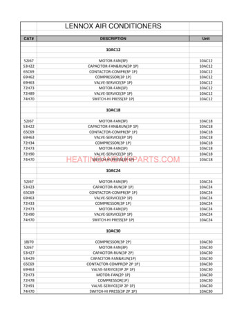
CB(X)26UH Series Air HandlersAll CB(X)26UH air handlers are designed for indoorinstallation only. As shipped, the units are ready forinstallation in either upflow or horizontal left hand airdischarge applications. All units may be installed withoptional field installed electric heat and a matched remoteoutdoor unit.S CBX26UH air handlers may be installed with amatched HFC 410A remote outdoor unit. These unitsare completely assembled, including a factoryinstalled check/expansion valve.S CB26UH air handlers may be installed with a matchedHCFC 22 remote outdoor unit. These units arecompletely assembled, including a factory installedcheck/expansion valve.Table 1. Orifice (RFC) Part Number (Sizes in.)HCFC 22 NOTE 1HFC 410A NOTE 2Model01813HPD / HP13100484 08 (0.057)XC13 / XP13024100484 11 (0.061)030100484 21 (0.072)036100484 23 (0.074)042100484 30 (0.082)037, 048not supported060100484 44 (0.098)Note 1 Orifice shipswith Air Handler.SRefer to orifice table inoutdoor unit installationmanualNote 2 Orifice ships withoutdoor units.CB26UH R (RFC) units may be installed with amatched remote 13HPD/ HP13 outdoor unit. Theseunits are equipped with an HCFC 22 refrigerant flowcontrol device (see orifice table 1). Also, these unitscan be used with HCFC 22 (13ACD/AC13), orHFC 410A refrigerant provided the RFC shipped withthe outdoor unit is installed in place of the RFC deviceshipped with the CB26UH R unit.Requirementsof Air Conditioning and Ventilation Systems" (NFPA No.90A) and Standard for Installation of Residence TypeWarm Air Heating and Air Conditioning Systems" (NFPANo. 90B).IMPORTANTThe CB(X)26UH units are designed to match, and mustbe used with, outdoor units as rated. The indoor sectionsare manufactured with a check/expansion valve (TXV)or refrigerant flow control (RFC) device to provide optimum refrigerant control and system performance with avariety of different capacities of outdoor units.TXV units In some cases, the rating of the outdoor unitmay require that the coil assembly installed TXV bechanged to obtain rated performance.All models are designed for indoor installation only. Theinstallation of the air handler, field wiring, duct system, etc.must conform to the requirements of the National ElectricalCode, ANSI/NFPA No. 70 (latest edition) in the UnitedStates, and any state laws, and local ordinances (includingplumbing or wastewater codes). Local authorities havingjurisdiction should be consulted before installation ismade. Such applicable regulations or requirements takeprecedence over the general instructions in this manual.Install the conditioned air plenum, ducts and air filters (notprovided) in accordance with NFPA 90B Standard for theInstallation of Warm Air Heating and Air ConditioningSystems (latest edition).The air handler is shipped from the factory completelyassembled. The unit is provided with flanges for theconnection of the duct system.Do not remove the cabinet knockouts until it has beendetermined which knockouts will need to be removed forthe installation.Select the final air discharge position which best suits thesite conditions. Consider required clearances, space,routing requirements for refrigerant line, condensatedisposal, filters, duct system, wiring, and accessibility forservice. Refer to the air handler rating plate on the airhandler for specific information.WARNINGWARNINGDanger of explosion. Keep flammable materials and vapors, such as gasoline, awayfrom air handler. Place air handler so thatheating elements are at least 18 inches (46cm) above the floor for a garage installation. Failure to follow these instructionscan result in death, explosion, or fire.Excessive Weight Hazard Use two or more peoplewhen moving and installing the unit. Failure to do so canresult in back or other type of injury.These instructions are intended as a general guide and donot supersede local or national codes in any way. Consultauthorities having jurisdiction before installation.Compliance with all local, state, or national codespertaining to this type of equipment should be determinedprior to installation. Read this instruction manual, as wellas the instructions supplied in separate equipment, beforestarting the installation.In addition to conforming to manufacturer’s installationinstructions and local municipal building codes, installationof Lennox air handler units (with or without optional electricheat), MUST conform with National Fire ProtectionAssociation (NFPA) standards: Standard for InstallationNOTES During cooling operation, excessive sweating may occur ifthe air handler is installed in a very humid space.If installed in an unconditioned space, sealant should beapplied around the electrical wires, refrigerant tubing, andcondensate lines where they enter the cabinet.Electrical wires should be sealed on the inside where theyexit the conduit opening. Sealant is required to prevent airleakage into, and condensate from forming inside of, theair handler, the control box, and on the electrical controls.Page 3CB(X)26UH SERIES
This unit is approved for installation clearance tocombustible material as stated on the unit rating plate.Accessibility and service clearances must takeprecedence over combustible material clearances.The air handler must be installed so that free access isallowed to the coil/filter compartment and blower/controlcompartment.Horizontal applications of the air handler must be installedsloped (approximately 5/8 inch) toward the drain panopenings to ensure proper condensate drainage.If a filter is to be installed at the air handler, early modelsrequire a filter rack be formed using factory suppliedflanges. Lay the unit on its back and pry out the filter racktabs as shown in figure 1. Repeat procedure on oppositeside.Installation ClearancesNON DUCTED RETURN CLOSET INSTALLATIONThe air handler can be installed in a closet with a falsebottom to form a return air plenum. It may also be installedwith a return air plenum under the air handler.Louvers or return air grilles are field-supplied. Local codesmay limit application of systems without a ducted return tosingle story buildings.When a CB(X)26UH unit is installed in a closet with alouvered return opening, the minimum open area for thelouvers will be:S 320 square inches for 018 and 024 models;S 360 square inches for 030 and 036 models;S 450 square inches for 042 thru 060 models.If the free area is not known, assume a 25% free area forwood or a 75% free area for metal louvers or grilles. Usingthe louver dimensions and the 25% or 75% assumption,determine if the open area meets the minimum open arealisted above.If a return air plenum is used, the return air grille should beimmediately in front of the opening in the plenum to allowfor the free flow of return air. When not installed in front ofthe opening, there must be adequate clearance around theair handler to allow for the free flow of return air.Figure 1. Filter Rack Tabs (Pre April 2006)Later models are equipped with rails in which the filterslides. Two screws and a bracket must be removed toinsert and remove the filter (see figure 2).BRACKETSCREWS(DUCT ADAPTER ANDSELF TAPPING SCREWS OPTIONAL FOR ATTACHING RETURN AIRDUCT)InstallationGENERAL INFORMATIONWARNINGFILTER RAILSImproper installation, adjustment, alteration, service ormaintenance can cause property damage, personal injury or loss of life. Installation and service must be performed by a qualified installer or service agency.CB(X)26UH units are factory assembled and configuredfor installation in upflow or horizontal left hand airdischarge applications.Each unit consists of a blower assembly, refrigerant coil,and controls, in an insulated galvanized steel factoryfinished enclosure. Knockouts are provided for electricalwiring entrance.For ease in installation, it is best to make any necessarycoil configuration changes before setting air handler inplace.Figure 2. Filter Rails (April 2006 and Later)UPFLOW APPLICATION1. The air handler must be supported on the bottom onlyand set on solid floor or field-supplied support frame.Securely attach the air handler to the floor or supportframe.2. If installing a unit in an upflow application, remove thehorizontal drain pan. IMPORTANT The horizontaldrain pan is not required in upflow air dischargeinstallations; its removal provides the bestefficiency and air flow.3. Place the unit in the desired location and level it.Connect return and supply air plenums as requiredusing sheet metal screws.Page 4505059M 0511
4. Install units that have no return air plenum on a standthat is at least 14" from the floor. This will allow properair return.HORIZONTAL DRAIN PANIMPORTANT! REMOVE PANFOR BEST EFFICIENCYAND AIR FLOW.HORIZONTAL DRAINCONNECTIONS(BOTH SIDES; NOTUSED)UPFLOWDRAIN PANUPFLOW DRAIN CONNECTIONS (BOTHSIDES; USE ONE SIDEOR OTHER)Figure 3. Upflow ConfigurationHORIZONTAL APPLICATIONSIMPORTANTNOTE This unit may be installed in left hand orright hand air discharge horizontal applications. Adequatesupport must be provided to ensure cabinet integrity.Ensure that there is adequate room to remove service andaccess panels if installing in the horizontal position.1. Determine whether left-hand or right-hand airdischarge is required. If right-hand is required, performRight Hand Discharge Modification on page 6.2. Determine knockouts required for drain lineconnections.3. With access door removed, knock out drain lineopening for installing drain lines.4. Set unit so that it is sloped toward the drain pan end ofthe unit (see figure 10 on page 7).5. The horizontal configuration i
manual 024 100484 11 (0.061) 030 100484 21 (0.072) 036 100484 23 (0.074) 042 100484 30 (0.082) 037, 048 not supported 060 100484 44 (0.098) Note 1 Orifice ships with Air Handler. Note 2 Orifice ships with outdoor units. CB26UH R (RFC) units may be installed with a matched remote 13HPD/ HP13 outdoor unit. These units are equipped with an HCFC 22 refrigerant flow control .