Transcription
WALK-IN BATH INSTALLATIONINSTRUCTIONS AND OWNER’S MANUAL
CONGRATULATIONS!You are now the owner of the world’s best walk-in bathtub from the inventor andmanufacturer of acrylic walk-in bathtubs.We thank you for your purchase. Your Safety Tub is a trueinvestment in your health and peace of mind.1100 Avenue S, Grand Prairie Texas 75050Customer Support: (877) 304-2800 Fax: (267) 295-1028info@safetytubs.com www.safetytubs.com1
OWNERS MANUALTABLE OF CONTENTSUNPACKING THE UNIT . Page 3RESPONSIBILITIES OF THE INSTALLER Page 4TESTING YOUR TUB BEFORE INSTALLATION Page 5INSTALLATION PREPARATION . Page 6ELECTRICAL INSTALLATION . Page 7INSTALLATION PROCEDURES . Page 8-17SAFETY INSTRUCTIONS . Page 19OPERATING INSTRUCTIONS . Page 20-21CLEANING & MAINTENANCE . Page 22WARRANTY . Page 23TROUBLE SHOOTING . Page 24-262
OWNERS MANUALUNPACKING THE UNIT1. FIRST, inspect the carton for damage: Take a picture if possible. CAREFULLYRECORD ALL PERCEIVED DAMAGE and call us at 877-304-2800.2. DO NOT LIFT THE TUB BY THE PLUMBING. Doing so can result in leaks, forwhich the installer is responsible. All Walk-In Tubs are water tested before theyleave our factory and the bath tub you have purchased has passed inspection.3. Immediately inspect the unit for damage even if there is no carton damage. Allproduct damage must be reported within 72hrs of receipt from Safety Tubs. Once theunit is installed, surface damages will be assumed to be installation-related if notreported prior to installation. Installers are also responsible for damage that occursonce the unit is placed in its niche.NOTE: Remove all packaging material except for the protective plastic. This hasbeen placed on the tub at the factory to eliminate abrasions from handling. Thisshould only be removed at final clean up.4. Inspect the plumbing for any fittings that may have loosened in transit.5. Read the following instructions completely before installing this product. If thehome-owner or installer has any questions, please call us at 1-877-304-2800.6. You must follow all the instructions in this manual.FAILURE TO READ AND COMPLY WITH ALL INSTRUCTIONS CAN RESULT INPRODUCT DAMAGE OR INJURY TO BOTH INSTALLER AND HOMEOWNER. ITWILL ALSO RESULT IN ASSUMPTION OF ALL LIABILITY BY SAID INSTALLER.3
OWNERS MANUALRESPONSIBILITIES OF THE INSTALLERThe installer must inspect and water test the product prior to installation to ensure the unit is free of defectand /or damage. In the event of a problem, the unit must not be installed. If the packaging or product hasbeen damaged, please call immediately at 1-877-304-2800.This product has been listed by INTERTEK / ETL and IAPMO / C UPC. The product has been tested andcomplies with the following standards and guidelines: IAPMO /C UPC, UL-1795, ANSI Z-124.1.2,ASME A 112.19.7, ASME A 112.19.15 & CSA B-45. The installer is responsible for compliance tostate and local codes.This product is designed to be installed by a licensed tradesperson. Licensed plumbers and electriciansshould be employed to insure proper installation. Installer assumes all liabilities for installationprocedures.Although Safety Tubs has taken reasonable precautions to ensure that the Minute Drain TM is suitablefor residential plumbing, it is the responsibility of the installer to insure that the plumbing is acceptablefor use of the Minute DrainTM . Safety Tubs does not accept responsibility for damage arising fromuse of the Minute DrainTM .Only accessories authorized by manufacturer should be used with this product.IMPORTANT SAFETY INSTRUCTIONSINSTRUCTIONS PERTAINING TO RISK OF FIRE,ELECTRICAL SHOCK OR INJURY TO PERSONSSAVE THESE INSTRUCTIONS!WARNING! ALL INSTRUCTIONS LISTED IN THIS MANUAL SHOULD BE READ ANDFOLLOWED CAREFULLY. ALL PRECAUTIONS PERTAINING TO RISK OF FIRE,ELECTRIC SHOCK, OR INJURY TO PERSONS MUST BE UNDERSTOOD ANDEXPLAINED TO OWNER.TO REDUCE THE RISK OF INJURY, CHILDREN OR PERSONS WITH INFIRMITIESMUST NOT BE PERMITTED TO USE THIS PRODUCT WITHOUT CLOSE ANDCONTINUOUS SUPERVISION.4
OWNERS MANUALTESTING YOUR WALK-IN TUB BEFORE INSTALLATION1. All Safety Tubs walk-in baths are 100% water tested at the factory and have passed inspection.Transportation and mishandling may loosen fittings and cause leaks. It is therefore necessary to test thebathtub while there is access to all sides of the bath.2. This unit should be both static and operationally tested with water. It is best to test the unit outside byfilling with a garden hose.a. Place the tub on a completely flat surface in an area where it may be drained after testing.b. Using a clean rag and warm water wipe down seal to insure it is free of debris.c. Seal the drain hole (this can be done with tape) and fill the tub to at least three inches above thehighest jet, or to the bottom of the safety bar if no jets are present.d. Allow the water to stand in tub for 30 minutes and then inspect all plumbing and seals forleaks.e. Using appropriately rated three-prong extension cords, all plugged in to separate outlets,operate all electrical components (air blower, water pump, and heater if applicable) for another30 minutes and inspect for leaks again. Inspect the unions around the pump and heater.f.If a leak persists at a union after tightening, it may have been over-tightened or might have adisplaced O-ring. Disassemble it and make sure the O-ring was seated properly. Do the same ifa leak persists at the heater. Verify that the heater threads match the pipe threads.g. Ensure that all jets are open and working, some hydro jets are adjustable for both flow rate anddirection of flow. The jet flow rate is adjusted by turning either the outside ring or the insidenozzle clockwise or counterclockwise. Some jets are not adjustable at the jet face, but can beadjusted by the “Legs Only Massage”. The “Legs Only Massage Valve” is located near theseat. (If Equipped.)3. If the pump/blower/heater does not operate:a. Check the breaker to ensure that power is on and make sure that any cables connecting thecontrol box to the switches and pumps are firmly attached. Verify the correct electrical circuitand amps of the testing cord.b. Go to the Trouble Shooting Guideline. (See pages 18–19.)c. Do not run any pumps unless the tub is filled with water to the proper level. Damage due to dryoperation of pumps is not covered under the warranty period.Failure to perform these tests before installation will make the installer liable for future repair costs.5
OWNERS MANUALINSTALLATION PREPARATION1. Check the floor area where the tub is to be installed.a. Clean area of any debris or trash.b. Use a 5 or 6-foot level and determine if the floor is level. If the floor is not level,adjust all 5 leveling feet to perfectly level the tub.Note: it is important that all leveling feet are completely touching the floor andlevel for the door system to work properly.2. Check to ensure that the drain piping has been “roughed-in” at the proper location. Seespecification sheets (installation detail), included in this manual.3. Ensure that the proper electrical service has been installed at the pump location. See electricalrequirements in the manual. (See page 7.)6
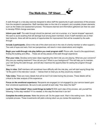
OWNERS MANUALELECTRICAL INSTALLATIONAll electrical wiring must be installed in accordance with the National Electrical Code and with alllocal codes. All wiring shall be done by a qualified electrician. Run one, two or three branch circuits(as required) from the main electrical service panel to the pump area of the framing structure toprovide power to the unitElectrical components have specific wiring requirements. Refer to the matrix below for the electricalsupply requirements for the jet massage bathtub and factory installed components.Branch circuits must be rated for 110 – 120 volts. Use 12 Gauge, 3 conductor cable for the circuits.If the length run exceeds 100 feet check with local codes for requirements. Install moisture proofjunction box(s) 6” above the floor at the pump end of the framing for each circuit.DO NOT INSTALL THE JUNCTION BOX(S) WHERE IT CAN BE REACHED WHILE SITTING ORSTANDING IN THE TUB OR TOUCHING THE FAUCETS.MINUTE DRAIN , LIGHTS, WHIRLPOOL, AIR SPA, COMBO & HEATERELECTRIAL REQUIREMENTSThis section lists the factory installed components of the Jet Massage and/or Air Massage Systems.Note the required number of circuits and their rating for the Jet Massage & Air Massage unit you are planning to install.CONFIGURATION LABEL FOR FACTORY INSTALLED COMPONENTSSystemsSoaker w / Minute Drain Electrical RatingCircuit 1Electrical RatingCircuit 215 Amp GFCISoaker w / Light15 Amp GFCISoaker w / Minute Drain w / Light15 Amp GFCIJet Massage Or Air Massage15 Amp GFCIJet Massage Or Air Massage w / Light15 Amp GFCIJet Massage Or Air Massage w/ Minute Drain 15 Amp GFCI15 Amp GFCIJet Massage Or Air Massage w/ Light & MinuteDrain 15 Amp GFCI15 Amp GFCIJet Massage & Air Massage (Dual)15 Amp GFCI15 Amp GFCIJet Massage & Air Massage (Dual) w/ Light15 Amp GFCI15 Amp GFCIJet Massage & Air Massage (Dual) w/ MinuteDrain 20 Amp GFCI15 Amp GFCI20 Amp GFCI15 Amp GFCIJet Massage & Air Massage (Dual) w/ Light &Minute Drain Whirlpool Inline Heater - Dedicated !5 AmpCircuitDedicatedCircuit15 Amp GFCIAll electrical connections must be carried out by a certified electrician in accordance with local electricalrequirements and codes.7
OWNERS MANUALINSTALLATION PROCEDURES WARNING: When installing jet massage baths, air massage baths, or dual massage baths, or MinuteDrain the following precautions must be followed: WARNING: Danger: Risk of electrical shock; connect components to separate circuits, EACH protectedby a ground fault circuit interrupter (GFCI) WARNING: Installation must provide access for servicing the pump and motor (all SafetyTubs walk-in tubs come with access panels for the pump, motor and faucet).1. Install tub waste/overflow according to instructions included with the provided kits. The Gel Coat Seriesrequires the installation of a door drain with check valve. The check valve and tubing must be installedhorizontal to the floor. Some installations will require the purchase of additional fittings2. Safety Tubs Faucet Installation # SFTY-TB Review the installation instructions packed with the faucet set. Mask off the tub’s deck with a protective tape. Locate and mark the center line of the overflow fitting Locate and mark 1 ½” line either side of the tub’s center line to establish the overflow clearance. Follow the drill template and faucet installation instructions.3. Other Faucet Model and / or Brand Review the installation instructions packed with the faucet set. Mask off the tub’s deck with a protective tape. Locate and mark the center line of the overflow fitting Locate and mark 1 ½” line either side of the tub’s center line to establish the overflow clearance. Verify the first two component mounting clearance on either side of the waste overflow as well asabove and below the tub’s deck. Verify the remaining component mounting clearance on both sides of the overflow as well as aboveand below the tub’s deck. It is recommended the hand held shower be installed on the corner closest to the wall to prevent waterfrom leaking off the deck and on to the floor.4. Install the optional in-line water heater per manufacturer’s instructions.5. Safety Tubs Walk-In Bath Installation - After framing is complete, set product in place to check fit andmake certain that the tub can be properly leveled. (Caution: If the bathtub is not resting on all leveling feet,water will not drain properly and this may cause the door to leak). Secure tub frame to the studs usingmetal straps. (Not provided.)8
OWNERS MANUALINSTALLATION PROCEDURES5a. Fire-Rated Drywall – If fire-rated drywall is specified, the finished fire-rated wall must be in place beforethe tub is installed. The dimensions of the framing structure must be increased by the thickness of firerated drywall.WARNING: Never allow the weight of the tub to be supported by wood support stringers and do not useintegral tile flange (if equipped) to screw or nail in place, as this will result in product failure and willvoid the warranty.6. Verify the product is completely level by checking tub deck surface and ensure all 5 leveling feet aretouching the ground.7. Electrical connection is made by simply plugging each cord into the GFCI outlet.7. After plumbing and electrical connections have been made the tub should be cleaned of dirt and debris.Use warm water and a non abrasive cleaner for clean up.9. Installation is not complete until the bathtub has been water-tested in place and does not leak.9
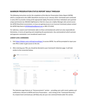
OWNERS MANUALGelcoat SS Series Models Installation DimensionsNon Integral FlangeIntegral FlangeModelSS 4828SS 5131SS 5230SS 5430SS 5530SS 6030A48”50 1/2"51 1/2"54"55"59 1/2"B28 1/2"31"29 3/4"29 1/2"29 3/4"29 3/4"C37 1/2"37 1/2"42"38"45 1/4"37 1/2"D11"9 1/2"12 1/29 1/2"10 1/2"9 1/4"E14 1/4"14 1/4"14 1/2"14 1/4"13 1/2"14 1/2"F16 3/4"15 1/2"17"16 1/4"16 1/2"15 1/4"Gn/a38 1/2"n/a39"46 1/4"n/aFlange DetailNo Integral FlangeIntegral FlangeNo Integral FlangeIntegral FlangeIntegral FlangeNo Integral FlangeTubs installed in an alcove installation require a raised flange to prevent water from seeping past the tub and into the wall.Tubs without a raised flange should be installed with a tile flange kit model TFK-60. The flange kit is a long plastic stripthat fits onto the rim of the tub to provide the leak protection needed.The tile flange should be installed on the tub before it is placed in the alcove. Install the tile flange along all sides of the tubwhere the wall will be. Measure to fit and miter cut the flange corners. The flange should be attached to the tub with aconstruction adhesive. Once the tub is in place to be installed and f
The installer must inspect and water test the product prior to installation to ensure the unit is free of defect and /or damage. In the event of a problem, the unit must not be installed. If the packaging or product has been damaged, please call immediately at 1-877-304-2800. This product has been listed by INTERTEK / ETL and IAPMO / C UPC. The product has been tested and complies with the .