Transcription
INSTALLATION INSTRUCTIONS30" (76 CM) FREESTANDING ELECTRIC RANGESTable of ContentsRANGE SAFETY .2INSTALLATION REQUIREMENTS.3Tools and Parts .3Location Requirements.3Electrical Requirements - U.S.A. Only.5INSTALLATION INSTRUCTIONS.6Unpack Range .6Install Anti-Tip Bracket.6Electrical Connection - U.S.A. Only.8Verify Anti-Tip Bracket Is Installed and Engaged.12Level Range .13Warming Drawer or Premium Storage Drawer.13Storage Drawer .14Oven Door .14Complete Installation .14Moving the Range.15IMPORTANT:Save for local electrical inspector's use.W10403811C
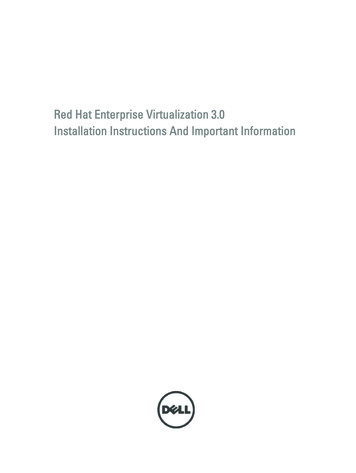
RANGE SAFETYYour safety and the safety of others are very important.We have provided many important safety messages in this manual and on your appliance. Always read and obey all safetymessages.This is the safety alert symbol.This symbol alerts you to potential hazards that can kill or hurt you and others.All safety messages will follow the safety alert symbol and either the word “DANGER” or “WARNING.”These words mean:DANGERWARNINGYou can be killed or seriously injured if you don't immediatelyfollow instructions.You can be killed or seriously injured if you don't followinstructions.All safety messages will tell you what the potential hazard is, tell you how to reduce the chance of injury, and tell you what canhappen if the instructions are not followed.WARNINGTip Over HazardA child or adult can tip the range and be killed.Install anti-tip bracket to floor or wall per installation instructions.Slide range back so rear range foot is engaged in the slot of the anti-tip bracket.Re-engage anti-tip bracket if range is moved.Do not operate range without anti-tip bracket installed and engaged.Failure to follow these instructions can result in death or serious burns to children and adults.To verify the anti-tip bracket is installed and engaged:Anti-TipBracket Slide range forward. Look for the anti-tip bracket securely attached to floor or wall. Slide range back so rear range foot is under anti-tip bracket.Range Foot2 See installation instructions for details.
INSTALLATION REQUIREMENTSTools and PartsLocation RequirementsGather the required tools and parts before starting installation.Read and follow the instructions provided with any tools listedhere.Tools needed Tape measure Masking tape Flat-blade screwdriver ¼" drive ratchet Phillips screwdriver ¼" nut driver Level ³ ₈" and ⁵ ₁₆" nut driver Hammer Hand or electric drill¹ ₈" (3.2 mm) drill bit (forwood floors) Tin snips or large wirecutters (for cutting groundstrap if necessary) Wrench or pliers Marker or pencilParts suppliedCheck that all parts are included. 3 - 10-32 hex nuts (attached to terminal block) 3 - Terminal lugsAIMPORTANT: Observe all governing codes and ordinances. It is the installer’s responsibility to comply with installationclearances specified on the model/serial rating plate. Themodel/serial rating plate is located on the frame behind a topcorner of the door or either side of the drawer. To eliminate the risk of burns or fire by reaching over heatedsurface units, cabinet storage space located above thesurface units should be avoided. If cabinet storage is to beprovided, the risk can be reduced by installing a range hoodthat projects horizontally a minimum of 5" (12.7 cm) beyondthe bottom of the cabinets. Cabinet opening dimensions that are shown must be used.Given dimensions are minimum clearances. The anti-tip bracket must be installed. To install the anti-tipbracket shipped with the range, see “Install Anti-Tip Bracket”section. Grounded electrical supply is required. See the appropriate“Electrical Requirements” section.IMPORTANT: To avoid damage to your cabinets, check with yourbuilder or cabinet supplier to make sure that the materials usedwill not discolor, delaminate or sustain other damage. This ovenhas been designed in accordance with the requirements of ULand CSA International and complies with the maximum allowablewood cabinet temperatures of 194 (90 C).BMobile Home - Additional Installation RequirementsA. Anti-tip bracketB. #12 x 1⁵ ₈" screws (2) Anti-tip bracket must be securely mounted to floor or wall.Thickness of flooring may require longer screws to anchorbracket to floor.The installation of this range must conform to the ManufacturedHome Construction and Safety Standard, Title 24 CFR, Part 3280(formerly the Federal Standard for Mobile Home Constructionand Safety, Title 24, HUD Part 280). When such standard is notapplicable, use the Standard for Manufactured HomeInstallations, ANSI A225.1/NFPA 501A or local codes.Mobile home installations require: When this range is installed in a mobile home, it must besecured per the instructions in this document. Four-wire power supply cord or cable must be used in amobile home installation. The appliance wiring will need to berevised. See “Electrical Connection - U.S.A. Only” section.Parts neededIf using a power supply cord kit: A UL listed power supply cord kit marked for use with ranges.The cord should be rated at 250 volts minimum, 40 amps or50 amps that is marked for use with nominal 1³ ₈" (3.5 cm)diameter connection opening and must end in ring terminalsor open-end spade terminals with upturned ends. A UL listed strain relief.Check local codes. Check existing electrical supply. See theappropriate “Electrical Requirements” section.It is recommended that all electrical connections be made by alicensed, qualified electrical installer.3
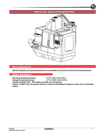
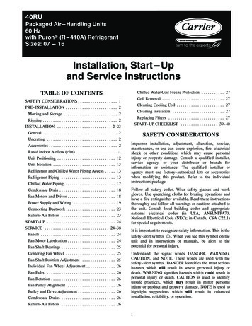
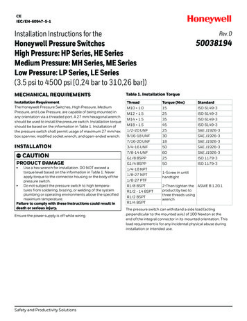
Product DimensionsCabinet DimensionsCabinet opening dimensions shown are for 25" (64.0 cm)countertop depth, 24" (61.0 cm) base cabinet depth and36" (91.4 cm) countertop height.IMPORTANT: If installing a range hood or microwave hoodcombination above the range, follow the range hood ormicrowave hood combination installation instructions fordimensional clearances above the cooktop surface.A freestanding range may be installed next to combustible wallswith zero clearance.ABACBCFDEDA. 27³ ₄" (70.5 cm) max. depth with handleB. 46⁷ ₈" (119.1 cm) overall height (max.) with leveling legsscrewed all the way in*C. 36" (91.4 cm) cooktop height (max.) with leveling legs screwedall the way in*D. 29⁷ ₈" (75.9 cm) widthE. 25⁵ ₁₆" (64.3 cm) depth - back of range to front of cooktop**F. Model/serial rating plate (located on the frame behind a topcorner of the door or either side of the drawer)IMPORTANT: Range must be level after installation. Follow theinstructions in the “Level Range” section. Using the cooktop as areference for leveling the range is not recommended.*Range can be raised approximately 1" (2.5 cm) by adjustingthe leveling legs.**Front of door and drawer may extend further forwarddepending on styling.4EFA. 13" (33.0 cm) max. upper cabinet depthB. 30" (76.2 cm) min. opening widthC. For minimum clearance to top of cooktop, see NOTE*D. 30¹ ₈" (76.5 cm) min. opening widthE. Outlet - 8" (20.3 cm) to 22" (55.9 cm) from either cabinet,5¹ ₂" (14.0 cm) max. from floorF. Cabinet door or hinges should not extend into the cutout*NOTE: 24" (61.0 cm) minimum when bottom of wood or metalcabinet is covered by not less than ¹ ₄" (0.64 cm) flame retardantmillboard covered with not less than No. 28 MSG sheet steel,0.015" (0.4 mm) stainless steel, 0.024" (0.6 mm) aluminum or0.020" (0.5 mm) copper.30" (76.2 cm) minimum clearance between the top of thecooking platform and the bottom of an uncovered wood or metalcabinet.
Electrical Requirements - U.S.A. OnlyIf codes permit and a separate ground wire is used, it isrecommended that a qualified electrical installer determine thatthe ground path and wire gauge are in accordance with localcodes.Do not use an extension cord.Be sure that the electrical connection and wire size are adequateand in conformance with the National Electrical Code, ANSI/NFPA 70-latest edition and all local codes and ordinances.A copy of the above code standards can be obtained from: A UL listed conduit connector must be provided at each endof the power supply cable (at the range and at the junctionbox). Wire sizes and connections must conform with the rating ofthe range. The wiring diagram is located on the Tech Sheet. The Tech Sheet is located on the back of the range inside aclear plastic bag.National Fire Protection Association1 Batterymarch ParkQuincy, MA 02169-7471WARNING: Improper connection of the equipment-groundingconductor can result in a risk of electric shock. Check with aqualified electrician or service technician if you are in doubt as towhether the appliance is properly grounded. Do not modify thepower supply cord plug. If it will not fit the outlet, have a properoutlet installed by a qualified electrician.If connecting to a 4-wire system:Electrical ConnectionTo properly install your range, you must determine the type ofelectrical connection you will be using and follow the instructionsprovided for it here. Range must be connected to the proper electrical voltageand frequency as specified on the model/serial rating plate.The model/serial rating plate is located on the frame behind atop corner of the door or either side of the drawer. Refer tothe figures in “Product Dimensions” in the “LocationRequirements” section. This range is manufactured with the neutral terminalconnected to the cabinet. Use a 3-wire, UL listed, 40- or50-amp power supply cord (pigtail) (see the following RangeRating chart). If local codes do not permit ground through theneutral, use a 4-wire power supply cord rated at 250 volts,40 or 50 amps and investigated for use with ranges.Range Rating*Specified Rating ofPower Supply Cord Kitand Circuit Protection120/240 Volts120/208 VoltsAmps8.8 - 16.5 KW16.6 - 22.5 KW7.8 - 12.5 KW12.6 - 18.5 KW40 or 50**50*The NEC calculated load is less than the total connected loadlisted on the model/serial rating plate.**If connecting to a 50-amp circuit, use a 50-amp rated cord withkit. For 50-amp rated cord kits, use kits that specify use with anominal 1³ ₈" (34.9 mm) diameter connection opening. A circuit breaker is recommended. The range can be connected directly to the circuit breakerbox (or fused disconnect) through flexible or nonmetallicsheathed, copper or aluminum cable. See the “ElectricalConnection - U.S.A. Only” section. Allow 2 to 3 ft (61.0 cm to 91.4 cm) of slack in the line so thatthe range can be moved if servicing is ever necessary.This range is manufactured with the ground connected to theneutral by a link. The ground must be revised so the greenground wire of the 4-wire power supply cord is connected to thecabinet. See “Electrical Connection - U.S.A. Only” section.Grounding through the neutral conductor is prohibited for newbranch-circuit installations (1996 NEC); mobile homes; andrecreational vehicles, or an area where local codes prohibitgrounding through the neutral conductor.When a 4-wire receptacle of NEMA Type 14-50R is used, amatching UL listed, 4-wire, 250-volt, 40- or 50-amp, range powersupply cord (pigtail) must be used. This cord contains 4 copperconductors with ring terminals or open-end spade terminals withupturned ends, terminating in a NEMA Type 14-50P plug on thesupply end.The fourth (grounding) conductor must be identified by a green orgreen/yellow cover and the neutral conductor by a white cover.Cord should be Type SRD or SRDT with a UL listed strain reliefand be at least 4 ft (1.22 m) long.4-wire receptacle (14-50R)The minimum conductor sized for the copper 4-wire powercord are:40-amp circuit2 No.-8 conductors1 No.-10 white neutral1 No.-8 green groundingIf connecting to a 3-wire system:Local codes may permit the use of a UL listed, 3-wire, 250-volt,40- or 50-amp range power supply cord (pigtail). This cordcontains 3 copper conductors with ring terminals or open-endspade terminals with upturned ends, terminating in a NEMA Type10-50P plug on the supply end. Connectors on the appliance endmust be provided at the point the power supply cord enters theappliance. This uses a 3-wire receptacle of NEMA Type 10-50R.3-wire receptacle (10-50R)5
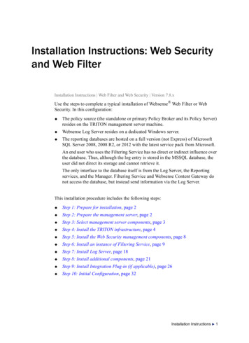
INSTALLATION INSTRUCTIONSUnpack RangeWARNINGInstall Anti-Tip BracketWARNINGExcessive Weight HazardUse two or more people to move and install range.Failure to do so can result in back or other injury.1. Remove shipping materials, tape and film from range.2. Remove oven racks and parts package from inside oven.3. Do not remove the shipping base at this time.Tip Over HazardA child or adult can tip the range and be killed.Install anti-tip bracket to floor or wall per installationinstructions.Slide range back so rear range foot is engaged in theslot of the anti-tip bracket.ARe-engage anti-tip bracket if range is moved.Do not operate range without anti-tip bracket installedand engaged.A. Shipping base4. On Ranges Equipped with a Storage Drawer:Remove the storage drawer. See the “Storage Drawer”section. Use a ¼" drive ratchet to lower the rear leveling legsone-half turn. Use a wrench or pliers to lower front levelinglegs one-half turn.ADFailure to follow these instructions can result in deathor serious burns to children and adults.
A child or adult can tip the range and be killed. Install anti-tip bracket to floor or wall per installation instructions. Slide range back so rear range foot is engaged in the slot of the anti-tip bracket. Re-engage anti-tip bracket if range is moved. Do not operate range without anti-tip bracket installed and engaged.