Transcription
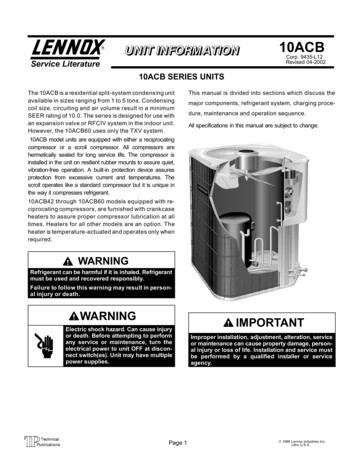
10ACBCorp. 9435 L12Revised 04 2002Service Literature10ACB SERIES UNITSThe 10ACB is a residential split system condensing unitavailable in sizes ranging from 1 to 5 tons. Condensingcoil size, circuiting and air volume result in a minimumSEER rating of 10.0. The series is designed for use withan expansion valve or RFCIV system in the indoor unit.However, the 10ACB60 uses only the TXV system.This manual is divided into sections which discuss themajor components, refrigerant system, charging proce dure, maintenance and operation sequence.All specifications in this manual are subject to change.10ACB model units are equipped with either a reciprocatingcompressor or a scroll compressor. All compressors arehermetically sealed for long service life. The compressor isinstalled in the unit on resilient rubber mounts to assure quiet,vibration free operation. A built in protection device assuresprotection from excessive current and temperatures. Thescroll operates like a standard compressor but it is unique inthe way it compresses refrigerant.10ACB42 through 10ACB60 models equipped with re ciprocating compressors, are furnished with crankcaseheaters to assure proper compressor lubrication at alltimes. Heaters for all other models are an option. Theheater is temperature actuated and operates only whenrequired.WARNINGRefrigerant can be harmful if it is inhaled. Refrigerantmust be used and recovered responsibly.Failure to follow this warning may result in person al injury or death.WARNINGElectric shock hazard. Can cause injuryor death. Before attempting to performany service or maintenance, turn theelectrical power to unit OFF at discon nect switch(es). Unit may have multiplepower supplies.Page 1IMPORTANTImproper installation, adjustment, alteration, serviceor maintenance can cause property damage, person al injury or loss of life. Installation and service mustbe performed by a qualified installer or serviceagency. 1999 Lennox Industries Inc.Litho U.S.A.
ELECTRICAL DATARECIPROCATING COMPRESSORS10ACB12 1 thru 10Model No.10ACB18 1 thru 1010ACB24 1 thru 1010ACB30 1 thru 10Line voltage data 60 hz 1phase4.9Power factor7.9.97Locked rotor ampsCondenserCoilFan Motor10ACB42 1 thru 1010ACB48 1 thru 910ACB60 1 thru 9208/230vRated load ampsCompressor10ACB36 1 thru 986069.49692.0110.0123.0Full load amps1.11.9Locked rotor amps1.94.1Rec. maximum fuse or circuit breakersize (amps)*Minimum circuit 5.5*Refer to National or Canadian Electrical Code manual to determine wire, fuse and disconnect size requirements.NOTE Extremes of operating range are plus 10% and minus 5% of line voltage.ELECTRICAL DATASCROLL COMPRESSORSModel No.10ACB42 11Line voltage data 60 hz 1 phaseCompressorCondenser CoilFan Motor10ACB48 1010ACB60 10208/230vRated load amps17.921.825Power factor.84.80.90Locked rotor amps103131170Full load amps1.11.9Locked rotor amps1.94.1Rec. maximum fuse or circuit breaker size (amps)*Minimum circuit ampacity40506023.031.235.5*Refer to National or Canadian Electrical Code manual to determine wire, fuse and disconnect size requirements.NOTE Extremes of operating range are plus 10% and minus 5% of line voltage.Page 2
SPECIFICATIONSModel No.10ACB12Outer coil10ACB1810ACB247.56 (0.70)10ACB3011.41 (1.06)10ACB3615.11 (1.40)Net face area sqsq. ftft. (m2)CondenserCoilInner coil Tube diameter in. (mm) & no. of rows5/16 (7.9) 1Fins per inch (m)Diameter in. (mm) & no. of blades18 (709)22 (866)18 (457) 318 (457) 4Motor hp (W)CondenserFan1/6 (124)Cfm (L/s)2400 (1135)2520 (1190)Rpm11051100Watts1702002 lbs. 12 oz.(1.25 kg)*Refrigerant charge furnished (HCFC 22)3 lbs. 10 oz.(1.64 kg)4 lbs. 0 oz.(1.81 kg){3/8 (9.5)Liquid line in. (mm) o.d. connection (sweat)Suction line in. (mm) o.d. connection (sweat)Shipping weight lbs. (kg) 1 package4 lbs. 0 oz.(1.81 kg)5 lbs. 0 oz.(2.26 kg)3/8 (9.5)5/8 (15.9)3/4 (19.1)146 (66)148 (67)150 (71)165 (75)OPTIONAL ACCESSORIES Must Be Ordered ExtraLow Ambient Kit for use with expansion valve systems onlyLB 57113BC (24H77)Crankcase Heater68887Timed Off ControlLB 61378A (47J35)Hail Guards17L71Unit Stand Off Kit17L7394J45Mounting BaseMB2 S (69J06)Compressor Monitor (Optional for Canada Only)t6 1469 (45F08)*Refrigerant charge sufficient for 20 ft. (6.0 m) length of refrigerant lines.{3/8 x 5/16 in. (9.5 x 7.9 mm) adaptor furnished for liquid line connection.Page 3
SPECIFICATIONS Cont.Model No.Net face area sqsq. ftft. (m2)CondenserCoil10ACB4210ACB48Outer coilInner coil5.40 (0.50)Tube diameter in. (mm) & no. of rows14.40 (1.34)5/16 (7.9) 1.37Fins per inch (m)5/16 (7.9) 222 (866)Diameter in. (mm) & no. of blades18 (457) 4Motor hp (W)CondenserCdFan10ACB6015.11 (1.40)1/6 (124)Cfm (L/s)1/3 (249)2500 (1180)2950 (1390)Rpm2930 (1385)1100Watts200*Refrigerant charge furnished (HCFC 22)3105 lbs. 7 oz. (2.47 kg)6 lbs. 6 oz. (2.89 kg)Liquid line in. (mm) o.d. connection (sweat)Suction line in. (mm) o.d. connection (sweat)Shipping weight lbs. (kg) 1 package8 lbs. 8 oz. (3.86 kg)3/8 (9.5)7/8 (22.2)1 1/8 (28.6)191 (87)196 (89)212 (96)OPTIONAL ACCESSORIES Must Be Ordered ExtraLow Ambient Kit for use with expansion valve systems onlyLB 57113BC (24H77)Crankcase Heater90P12Timed Off ControlLB 61378A (47J35)Hail Guards17L73Unit Stand Off Kit94J45Mounting BaseMB2 S (69J06)Compressor Monitor (Optional for Canada Only)T6 1469 (45F08)*Refrigerant charge sufficient for 20 ft. (6.0 m) length of refrigerant lines.I UNIT INFORMATION10ACB UNIT COMPONENTSOUTDOORFAN/MOTORDANGERCONTROLBOXMake sure all power is disconnected beforebeginning electrical service procedures.10ACB condensing units are available in 1, 1 1/2, 2, 2 1/2, 3,3 1/2, 4 and 5 ton capacities.All major components (indoor blower and coil) must bematched according to Lennox recommendations for the com pressor to be covered under warranty. Refer to the Engineer ing Handbook for approved system matchups. A misappliedsystem will cause erratic operation and can result in early com pressor failure.DISCHARGELINESUCTION LINESERVICE VALVEII UNIT COMPONENTSUnit components are illustrated in figure 1.COMPRESSORLIQUID LINESERVICE VALVESUCTION LINEFIGURE 1Page 4
10ACB UNIT CONTROL BOXRECIPROCATING COMPRESSORDUAL CAPACITOR(C12)STARTCAPACITOR (C7)(3.5, 4 & 5 ton)10ACB units are not equipped with a 24V transformer. All24 VAC controls are powered by the indoor unit. Refer towiring diagram.DANGERShock HazardSome 10ACB units use single polecontactors. One leg of compres sor, capacitor and condenser fanare connected to line voltage at alltimes. Potential exists for electri cal shock resulting in injury ordeath. Remove all power at dis connect before servicing.Can cause personal injury or death.COMPRESSORCONTACTOR(K1)POTENTIALRELAY (K31)(3.5, 4 & 5 ton)GROUNDINGLUG2 Dual Capacitor C12FIGURE 210ACB UNIT CONTROL BOX 042, 048 and 060 with ScrollDUAL CAPACITOR(C12)The compressor and fan in 10ACB series units use per manent split capacitor motors. The capacitor is locatedinside the unit control box (see figures 2 and 3). A single dual" capacitor (C12) is used for both the fan motor andthe compressor (see unit wiring diagram). The fan sideand the compressor side of the capacitor have differentMFD ratings. For ratings see side of capacitor.3 Start Capacitor C7COMPRESSORCONTACTOR(K1)All 10ACB 3 1/2, 4 and 5 ton series units equipped with areciprocating compressor, use a start capacitor (C7) wiredin parallel with the compressor side of the dual capacitor.The capacitor is located inside the unit control box (seefigure 2). C7 is switched off by potential relay (K31) whenthe compressor nears full speed. The start capacitor israted at 330 VAC and has an MFD rating of 176 216.GROUNDINGLUG4 Potential (Start) Relay K31FIGURE 3A Control Box (Figures 2 & 3)Electrical openings are provided under the control box cov er. Field thermostat wiring is made to color coded pigtailconnections.1 Compressor Contactor K1The compressor is energized by a contactor located in thecontrol box. See figure 2. Single pole and two pole con tactors are used in 10ACB units. See wiring diagrams forspecific units. K1 is energized by the indoor thermostatterminal Y1 (24V) when thermostat demand is present.Page 5All 10ACB 3 1/2, 4 and 5 ton series units equipped with a re ciprocating compressor use a potential relay which controlsthe operation of the starting circuit. The potential relay islocated inside the unit control box (see figure 2). Therelay is normally closed when contactor K1 is de ener gized. When K1 energizes, the compressor immediatelybegins start up. K31 remains closed during compressorstart up and the start capacitor C7 remains in the circuit.When the compressor reaches 75% of its speed, K31 is ener gized. When K31 energizes, the contacts open and the startcapacitor C7 is taken out of the circuit.
B CompressorCROSS SECTION OF SCROLLSAll 10ACB units built prior to May of 1998 utilize a con ventional reciprocating compressor. 10ACB 042, 048and 060 units built after May of 1998 will be equippedwith a scroll compressor. For compressor specifica tions see ELECTRICAL DATA" section in this manual orthe compressor nameplate.DISCHARGESTATIONARY SCROLLDISCHARGEPRESSURESUCTIONSCROLL COMPRESSORDISCHARGEORBITING SCROLLTIPS SEALED BYDISCHARGE PRESSUREFIGURE 6SUCTIONFIGURE 41 Scroll CompressorThe scroll compressor design is simple, efficient and re quires few moving parts. A cutaway diagram of the scrollcompressor is shown in figure 4.The scrolls are located inthe top of the compressor can and the motor is located justbelow. The oil level is immediately below the motor.The scroll is a simple compression concept centeredaround the unique spiral shape of the scroll and its inherentproperties. Figure 5 shows the basic scroll form. Two iden tical scrolls are mated together forming concentric spiralshapes (figure 6 ). One scroll remains stationary, while theother is allowed to orbit" (figure 7). Note that the orbitingscroll does not rotate or turn but merely orbits" the station ary scroll.SCROLL FORMThe counterclockwise orbiting scroll draws gas into the out er crescent shaped gas pocket created by the two scrolls(figure 7 1). The centrifugal action of the orbiting scrollseals off the flanks of the scrolls (figure 7 2). As the orbitingmotion continues, the gas is forced toward the center of thescroll and the gas pocket becomes compressed (figure 7 3). When the compressed gas reaches the center, it is dis charged vertically into a chamber and discharge port in thetop of the compressor (figure 6). The discharge pressureforcing down on the top scroll helps seal off the upper andlower edges (tips) of the scrolls (figure 6 ). During a singleorbit, several pockets of gas are compressed simultaneous ly providing smooth continuous compression.The scroll compressor is tolerant to the effects of liquid re turn. If liquid enters the scrolls, the orbiting scroll is allowedto separate from the stationary scroll. The liquid is workedtoward the center of the scroll and is discharged. If thecompressor is replaced, conventional Lennox cleanuppractices must be used.Due to its efficiency, the scroll compressor is capable ofdrawing a much deeper vacuum than reciprocating com pressors. Deep vacuum operation can cause internal fu site arcing resulting in damaged internal parts and will re sult in compressor failure. Never use a scroll compressorfor evacuating or pumping down" the system. This type ofdamage can be detected and will result in denial of warran ty claims.NOTE During operation, the head of a scroll compressormay be hot since it is in constant contact with dischargegas.FIGURE 5Page 6
HOW A SCROLL WORKSSUCTIONMOVEMENT OF ORBITSUCTIONINTERMEDIATEPRESSUREGASCRESCENTSHAPED GASPOCKETORBITINGSCROLLSUCTIONPOCKET21FLANKSSEALED BYCENTRIFUGALFORCESTATIONARY ETFIGURE 72 Crankcase HeaterA crankcase heater is used on all 10ACB42 through10ACB60 models equipped with a reciprocating com pressor. For all other models the crankcase heater is anoption and must be ordered seperate. See SPECIFI CATIONS" section in this manual for part number. Thewell mounted insertion type heater is self regulating.All heaters used on reciprocating compressors arerated at 27 watts. The heater is temperature actuatedand operates only when required.CONDENSER FAN MOTORAND COMPRESSOR ACCESSFAN GUARDRemove (7) screwsFANMOTORWIRINGC Condenser Fan MotorAll units use single phase PSC fan motors which require a runcapacitor. In all units, the condenser fan is controlled by thecompressor contactor.ELECTRICAL DATA tables in this manual show specifi cations for condenser fans used in 10ACBs.Access to the condenser fan motor on all units is gainedby removing the seven screws securing the fan assem bly. See figure 8. The condenser fan motor is removedfrom the fan guard by removing the four nuts found onthe top panel. See figure 9 if condenser fan motor re placement is necessary.RACEWAYRemove (4) nutsREMOVE (7) SCREWSSECURING FAN GUARD.REMOVE FAN GUARD/FANASSEMBLY.FIGURE 8ALIGN FAN HUB FLUSH WITH END OF SHAFTFIGURE 9Page 7
III REFRIGERANT SYSTEMA PlumbingDANGERField refrigerant piping consists of liquid and suction linesfrom the condensing unit (sweat connections) to the indoorevaporator coil (flare or sweat connections). Use LennoxL10 (flare) or L15 (sweat, non flare) series line sets asshown in table 1 or use field fabricated refrigerant lines.Separate discharge and suction service ports are pro vided outside the unit for connection of gauge manifoldduring charging procedure.TABLE 1CondensingUnitModel 4810ACB60Length of Liquid Line Suction LineLine SetLinesOutside Dia. Outside Dia.Model No.(L10 or L15) ft.min.mmin.mmL10/15 21 20206L10/15 21 25258L10/15 21 353511L10/15 21 505015L10/15 41 20206L10/15 41 30309L10/15 41 404012L10/15 41 505015L10/15 65 30309L10/15 65 404012L10/15 65 505015*Field fabricate5/16797.95/8Do not attempt to backseat this valve. Attempts tobackseat this valve will cause snap ring to explodefrom valve body under pressure of refrigerant.Personal injury and unit damage will result.To Close Liquid or Suction Line Service Valve:1 Remove stem cap with an adjustable wrench.2 Using service wrench and 5/16" hex head extension, turnstem clockwise to seat the valve. Tighten firmly.3 Replace stem cap. Tighten finger tight, then tighten anadditional 1/6 turn.LIQUID LINE SERVICE VALVE (VALVE OPEN)15 915.9INSERT HEXWRENCH HERE3/8959.53/4193/89.57/822.23/89.51 1/828.5STEM CAPSER VICEPORTOUTLET (TOCOMPRESSOR)*Field fabricate. See Corp. 9351 L9 Refrigerant Piping NabualB Service ValvesSERVICEPORTCAPThe liquid and suction line service valves (figures 10 and 11)and gauge ports are accessible from outside the unit.The valve is equipped with a service port. The service portsare used for leak testing, evacuating, charging and checkingcharge. A schrader valve is factory installed. A service port capis supplied to protect the schrader valve from contaminationand serve as the primary leak seal.NOTE Always keep valve stem caps clean.To Access Schrader Port:1 Remove service port cap with an adjustable wrench.INLET (TOINDOOR COIL)SCHRADERVALVELIQUID LINE SERVICE VALVE (VALVE CLOSED)RETAINING RINGSTEM CAPSERVICEPORTINSERT HEXWRENCH HEREOUTLET (TOCOMPRESSOR)2 Connect gauge to the service port.3 When testing is completed, replace service port cap.Tighten finger tight, then an additional 1/6 turn.To Open Liquid or Suction Line Service Valve:1 Remove stem cap with an adjustable wrench.2 Using service wrench and 5/16" hex head extensionback the stem out counterclockwise until the valve stemjust touches the retaining ring.3 Replace stem cap tighten firmly. Tighten finger tight, thentighten an additional 1/6 turn.SERVICEPORT CAPSCHRADER VALVE OPENTO LINE SET WHEN VALVEIS CLOSED (FRONTSEATED)INLET(TO INDOOR COIL)(VALVE FRONTSEATED)FIGURE 10Page 8
SUCTION LINE (BALL TYPE) SERVICE VALVE(VALVE OPEN)SUCTION LINE SERVICE VALVE (VALVE OPEN)INSERT HEXWRENCH HEREUSE ADJUSTABLE WRENCHROTATE STEM CLOCKWISE 90 TO CLOSEROTATE STEM COUNTER CLOCKWISE 90 TO OPENSTEM CAPINLET (TOINDOOR COIL)STEM CAPINLET(FROM INDOOR COIL)STEMSCHRADERVALVEBALL(SHOWN OPEN)OUTLET (TOCOMPRESSOR)OUTLET(TOCOMPRESSOR)SERVICE PORTCAPSERVICE PORTSUCTION LINE SERVICE VALVE (VALVE CLOSED)INLET (TOINDOOR COIL)RETAINING RINGSERVICEPORTCAPSERVICE PORTSCHRADER COREFIGURE 12STEM CAPIV CHARGINGThe unit is factory charged with the amount of R 22 refrig INSERT HEXWRENCH HEREerant indicated on the unit rating plate. This charge isSERVICEPORTbased on a matching indoor coil and outdoor coil with a 20(VALVE FRONTSEATED)foot (6.1 m) line set. For varying lengths of line set, refer totable 2 for refrigerant charge adjustment. A blank space is pro vided on the unit rating plate to list actual field charge.SERVICE PORTCAPSCHRADER VALVE OPENTO LINE SET WHEN VALVE ISCLOSED (FRONT SEATED)TABLE 2OUTLET (TOCOMPRESSOR)LIQUID LINESET DIAMETER1/4 in. (6 mm)5/16 in. (8mm)3/8 in. (10 mm)FIGURE 11Ounce per 5 foot (ml per mm) adjustfrom 20 foot (6.1 m) line set*1 ounce per 5 feet (30 ml per 1524 mm)2 ounce per 5 feet (60 ml per 1524 mm)3 ounce per 5 feet (90 ml per 1524 mm)*If line set is greater than 20 ft. (6.1 m) add this amount. If line setis less than 20 feet (6.1 m) subtract this amountSuction Line (Ball Type) Service Valve(5 Ton Only)Units are designed for line sets up to 50 ft (15.2 m). Con A ball type full service valve is used on 10ACB 5 tonunits. These suction line service valves function thesame way, differences are in construction. Valves arenot rebuildable. If a valve has failed it must be replaced. A ballvalve is illustrated in figure 12.The ball valve is equipped with a service port. A schrader valveis factory installed. A service port cap is supplied to protect theschrader valve from contamination and assure a leak freeseal.Page 9sult Lennox Refrigerant Piping Manual for line sets over50 ft (15.2 m).IMPORTANTIf line length is greater than 20 feet (6.1 m) add thisamount. If line length is less than 20 feet (6.1 m),subtract this amount. See table 2.
A Pumping Down SystemCAUTIONDeep vacuum operation (operating compressor at 0psig or lower) can cause internal fusite arcingresulting in a damaged or failed compressor. Thistype of damage will result in denial of warranty claim.The system may be pumped down when leak checking theline set and indoor coil or making repairs to the line set orindoor coil.1 Attach gauge manifold.2 Front seat (close) liquid line valve.3 Start outdoor unit.4 Monitor suction gauge. Stop unit when 0 psig is reached.5 Front seat (close) suction line valve.B Leak Testing (To Be DoneBefore Evacuating)1 Attach gauge manifold and connect a drum of dry nitro gen to center port of gauge manifold.2 Open high pressure valve on gauge manifold andpressurize line set and indoor coil to 150 psig (1034kPa).3 Check lines and connections for leaks.NOTE If electronic leak or Halide detector is used, add asmall amount of R 22 (3 to 5 psig [20kPa to 34kPa]) thenpressurize with nitrogen to 150 psig.4 Release nitrogen pressure from the system, correct anyleaks and recheck.CAUTIONWhen using dry nitrogen, a pressure reducing reg ulator must be used to prevent excessive pres sure in gauge manifold, connecting hoses, andwithin the system. Regulator setting must not ex ceed 150 psig (1034 kpa). Failure to use a regulatorcan cause equipment failure resulting in injury.C Evacuating the SystemA temperature vacuum gauge, mercury vacuum(U tube), or thermocouple gauge should be used.The usual Bourdon tube gauges are not accurateenough in the vacuum range.IMPORTANTThe compressor should never be used to evacu ate a refrigeration or air conditioning system.D ChargingIf the system is completely void of refrigerant, the recom mended a
Page 1 1999 Lennox Industries Inc. Litho U.S.A. Corp. 9435 L12 10ACB Service Literature Revised 04 2002 10ACB SERIES UNITS The 10ACB is a residential splitsystem condensing unit available in sizes ranging from 1 to 5 tons. Condensing coil size, circuiting and air volume result in a minimum SEER rating of 10.0. The series is designed for use .