Transcription
ESP-WROOM-S2FONOTRERCNE OMWM(NEDRN ES NDD) IG EDNSDatasheetVersion 2.6Espressif SystemsCopyright 2022www.espressif.com
About This GuideThis document introduces the specifications of ESP-WROOM-S2 hardware.Release NotesDateVersionRelease notes2016.06V1.0First release. Updated the operating temperature range;2016.08V1.1 Added NCC Wi-Fi standard; Updated Section 3.4 “Interface Description”.2016.11V1.22016.12V1.32017.02V1.4 Added Appendix—Learning Resources; Added “ESP-WROOM-S2 Peripheral Schematics” in Chapter 5. Changed the minimum working voltage from 3.0V to 2.5V; Changed the power consumption during Deep-sleep from 10 μA to 20 μA.Updated Section 3.3. Added Documentation Change Notification and the official link for downloadingProduct Certifications; Updated the supply voltage to 2.7V 3.6V;2017.09V1.5 Updated Figure 2-1 and added a note to it. Updated Chapter 4: Combined electrical-characteristics-related data into Table4-1; combined Wi-Fi-radio-related data into Table 4-2 and updated the outputpower parameters; updated Reflow Profile; Updated Chapter 5 Schematics and added a note. Updated RF certification;2017.10V1.6 Update the chip output impedance to 39 j6Ω in Table 4-2; Updated the note for the peripheral schematics. Updated the note for the peripheral schematics.2018.04V1.7 Updated the link of ESP8266 Apps and ESP8266 Hardware Resources in theappendix A.1. Updated reflow profile;2018.09V1.8 Updated module dimensions data; Added module dimensions; Added PCB land pattern. Added information about green certificates and MSL information in table 1-2;2019.03V1.9 Removed duplicate information in Table 4-1; Added notes in Figure 5-1.2019.08V2.0Updated Chapter 6 Peripheral Schematics.Not Recommended For New Designs (NRND)
DateVersionRelease hanged the schematics.2021.08V2.5Added the “Not Recommended For New Designs (NRND)” watermark andfooters.2022.03V2.6Added a link to RF certification in Table 1-1 Added a note for the reflow profile; Added feedback links.Removed a note regarding customized variants in Chapter 1. Updated Note in Chapter 6; Updated links in Appendix.Documentation Change NotificationEspressif provides email notifications to keep customers updated on changes totechnical documentation. Please subscribe at onDownload certificates for Espressif products from https://www.espressif.com/en/certificates.Not Recommended For New Designs (NRND)
Table of Contents1. Overview . 12. Pin Description .33. Functional Description .63.1. MCU .63.2. Memory .63.2.1.Internal SRAM and ROM .63.2.2.SPI Flash .63.3. Crystal Oscillator .73.4. Interface Description .74. Electrical Characteristics . 94.1. Electrical Characteristics .94.2. Wi-Fi Radio .94.3. Power Consumption .104.4. Reflow Profile .115. Schematics .126. Peripheral Schematics .137. Dimensions .148. Recommended PCB Land Pattern . 15A. Appendix - Learning Resources .16A.1. Must-Read Documents .16A.2. Must-Have Resources .17Not Recommended For New Designs (NRND)
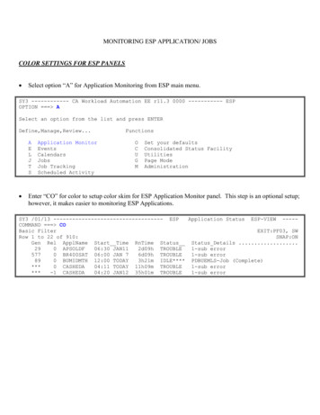
1. Overview#1.OverviewEspressif provides the SMD module—ESP-WROOM-S2 that integrates ESP8266EX. Themodule has been adjusted to achieve the best RF performance. We recommend usingESP-WROOM-S2 for tests or for further development. Note:For more information on ESP8266EX, please refer to ESP8266EX Datasheet.The flash used on this module is a 2-MB SPI flash connected to HSPI, with a package sizeof SOP 8-150 mil. The gain of the on-board PCB antenna is 2 dBi.The ESP-WROOM-S2 works as the SDIO/SPI slave with the SPI speed of up to 8 Mbps.##Figure 1-1. ESP-WROOM-S2 ModuleTable 1-1. ESP-WROOM-S2 ationsRF certificationSee certificates from ESP-WROOM-S2Green certificationRoHS, REACHWi-Fi protocols802.11 b/g/nFrequency range2.4 GHz 2.5 GHz (2400 MHz 2483.5 MHz)Wi-FiPeripheral interfaceUART/I2C/GPIO/PWM/SDIO/SPI/IR Remote Control/ADCGPIO/PWMEspressifNot Recommended For New Designs (NRND)#1/182022.03Submit Documentation Feedback
1. ionsOperating voltage2.7 V 3.6 VOperating currentAverage: 80 mAMinimum current delivered bypower supply500 mAOperating temperature range-40 C 85 CPackage size (mm)(16.00 0.10) x (23 0.10) x (2.8 0.10)External interface-Moisture sensitivity levelLevel 3Wi-Fi modeStation/SoftAP/SoftAP are upgradeUART Download / OTA (via network) / Download andwrite firmware via hostSoftware developmentEspressifSupports Cloud Server DevelopmentSDK for secondary developmentNetwork protocolsIPv4, TCP/UDP/HTTP/FTPUser configurationAT Instruction Set, Cloud Server, Android/iOS appNot Recommended For New Designs (NRND)#2/182022.03Submit Documentation Feedback
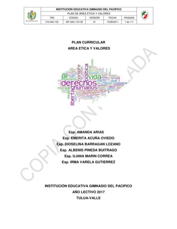
2. Pin Description#2.Pin DescriptionFigure 2-1 shows the pin distribution of ESP-WROOM-S2.16.00PCB ANTENNA6.0015.701GND23V3320ADC 0.90Unit: mmFigure 2-1. ESP-WROOM-S2 Pin Layout (Top View)EspressifNot Recommended For New Designs (NRND)#3/182022.03Submit Documentation Feedback
2. Pin Description#ESP-WROOM-S2 has 20 pins, please see the pin definitions in Table 2-1.Table 2-1. ESP-WROOM-S2 Pin DefinitionsNo.Pin NameFunctional Description1GNDGround3.3 V power supply (VDD)23V3 Note:It is recommended the maximum output current a power supply providesbe of 500 mA or above.3IO16GPIO16; used for Deep-sleep wake-up when connected to RST pin.HSPICS4IO15UART download: pull down.SDIO boot: floating (internal pull-up) or pull up.GPIO2; UART1 TXD5IO2UART download: pull down.SDIO boot: don’t-care.GPIO06IO0UART download: pull down.SDIO boot: don’t-care.7IO4GPIO48SD2/IO9SD D2 (Series resistor: 100 200 Ω, 10k pull-up resistor); GPIO99SD3/CSSD D3 (Series resistor: 100 200 Ω, 10k pull-up resistor); SLAVE SPI CS10CMD/MOSISD CMD (Series resistor: 100 200 Ω, 10k pull-up resistor);SLAVE SPI MOSI11GNDGround12SCLKSD CLK (Series resistor: 100 200 Ω); SLAVE SPI CLK13SD0/MISOSD D0 (Series resistor: 100 200 Ω, 10k pull-up resistor);SLAVE SPI MISO14SD1/INTSD D1 (Series resistor: 100 200 Ω, 10k pull-up resistor); SLAVE SPI INT15RXD16TXDUART0 RXD, receive end in UART download;GPIO3UART0 TXD, transmit end in UART download, floating (internal pull-up) orpull up;GPIO1EspressifNot Recommended For New Designs (NRND)#4/182022.03Submit Documentation Feedback
2. Pin Description#EspressifNo.Pin NameFunctional Description17IO5GPIO518RSTReset19ADC INTests the power-supply voltage of VDD3P3 and the input power voltage ofTOUT. These two functions cannot be used simultaneously.20ENChip enable pin (cannot be floating). Active high.Not Recommended For New Designs (NRND)#5/182022.03Submit Documentation Feedback
3. Functional Description#3.Functional Description3.1. MCUESP8266EX contained in the ESP-WROOM-S2 integrates Tensilica L106 32-bitmicrocontroller (MCU) and a 16-bit RSIC. The CPU clock speed is 80 MHz and can reach amaximum value of 160 MHz. The system can readily run a Real-Time Operating System(RTOS). Currently, the Wi-Fi stack only takes up 20% of CPU time. The remaining CPU time(80% of total MIPS) can be used for user applications. The MCU can work in conjunctionwith the other parts of the chip through the following interfaces. Programmable RAM/ROM interface (iBus) that connects to the memory controller andcan access the external flash. Data RAM interface (dBus) that connects to memory controller. AHB interface that accesses the register.3.2. Memory3.2.1. Internal SRAM and ROMESP8266EX Wi-Fi SoC integrates the memory controller including ROM and SRAM. MCUcan access the memory controller through iBus, dBus, and AHB interfaces. All theseinterfaces can access ROM or RAM units. A memory arbiter determines the runningsequence in the arrival order of requests.According to our current version of SDK, SRAM space available to users is assigned asfollows. RAM size 50 kB, that is, when ESP8266EX is working in Station mode and connectsto the router, available space in the Heap Data sector is around 50 kB. There is no programmable ROM in ESP8266EX, therefore, user program must be storedin the SPI flash integrated into the ESP-WROOM-S2.3.2.2. SPI FlashESP8266EX supports SPI flash. Theoretically speaking, ESP8266EX can support an upto-16-MB SPI flash.ESP-WROOM-S2 currently integrates a 2-MB SPI flash. ESP-WROOM-S2 supports theseSPI modes: Standard SPI, DIO (Dual I/O), DOUT (Dual Output), QIO (Quad I/O) and QOUT(Quad Output).EspressifNot Recommended For New Designs (NRND)#6/182022.03Submit Documentation Feedback
3. Functional Description# Notice:Please use the most updated download tool and configure SPI MODE in the download tool as DIO orDOUT.3.3. Crystal OscillatorESP-WROOM-S2 uses a 26 MHz crystal oscillator. The accuracy of the crystal oscillatorshould be 10 PPM.When using the download tool, please note to select the right crystal oscillator type. Incircuit design, capacitors C1 and C2 which connect to the earth are added to the input andoutput terminals of the crystal oscillator respectively. The values of the two capacitors canbe flexible, ranging from 6 pF to 22 pF, however, the specific capacitive values depend onfurther testing of, and adjustment to, the overall performance of the whole circuit. Normally,the capacitive values of C1 and C2 are within 10 pF for the 26 MHz crystal oscillator.3.4. Interface DescriptionTable 3-1. Interface DescriptionInterfaceEspressifPinFunctional DescriptionSPIGPIO12/13/14/15 or GPIO6/7/8/11S2 can control SPI Slave as a Master or communicatewith Host MCU as a Slave. In overlap mode, S2 canshare the SPI interface with Flash, shifted by different CSsignals.PWMAny available GPIO (EXCEPTGPIO16)Currently the demo provides four PWM channels (userscan extend to six channels). PWM interface can realizethe control of LED lights, buzzers, relays, electronicmachines, etc.IRAny available GPIO (EXCEPTGPIO16)The functionality of the infrared remote control interfacecan be realized via software programming. The interfaceuses NEC coding, modulation, and demodulation. Thefrequency of the modulated carrier signal is 38 kHz.ADCTOUTTests the power supply voltage of VDD3P3 (Pin3 andPin4) and the input power voltage of TOUT (Pin6).However, these two functions cannot be usedsimultaneously. This interface is typically used in sensors.I2CAny available GPIO (EXCEPTGPIO16)Connects to external sensors and display screens, etc.Not Recommended For New Designs (NRND)#7/182022.03Submit Documentation Feedback
3. Functional Description#InterfacePinFunctional DescriptionCommunicates with UART device.UART0:UARTDownloading: U0TXD U0RXD or GPIO2 U0RXDTXD(U0TXD),Communicating (UART0): U0TXD, U0RXDRXD(U0RXD)UART1: IO2(TXD)EspressifDebugging: UART1 TXD (GPIO2) can be used to printdebugging information.Not Recommended For New Designs (NRND)#8/182022.03Submit Documentation Feedback
4. Electrical Characteristics#4.Electrical Characteristics Note:Unless otherwise specified, measurements are based on VDD 3.3 V, TA 25 C.4.1. Electrical CharacteristicsTable 4-1. Electrical CharacteristicsParameterSymbolMinTypMaxUnitMaximum soldering temperature(Condition: IPC/JEDEC J-STD-020)---260 Supply voltageVDD2.73.33.6VInput logic level lowVIL-0.3-0.25 VDDVInput logic level highVIH0.75 VDD-VDD 0.3VOutput logic level lowVOL--0.1 VDDVOutput logic level highVOH0.8 VDD--V4.2. Wi-Fi RadioTable 4-2. Wi-Fi Radio CharacteristicsDescriptionMinTypMaxUnitInput frequency2400-2483.5MHzInput reflection---10dBPA output power at 72.2 Mbps131415dBmPA output power in 11b mode19.52020.5dBmDSSS,1 Mbps--98-dBmCCK, 11 Mbps--91-dBm6 Mbps (1/2 BPSK)--93-dBm54 Mbps (3/4 64-QAM)--75-dBmOutput PowerSensitivityEspressifNot Recommended For New Designs (NRND)#9/182022.03Submit Documentation Feedback
4. Electrical Characteristics#DescriptionMinTypMaxUnitHT20, MCS7 (65 Mbps, 72.2 Mbps)--72-dBmOFDM, 6 Mbps-37-dBOFDM, 54 Mbps-21-dBHT20, MCS0-37-dBHT20, MCS7-20-dBAdjacent channel rejection4.3. Power ConsumptionThe following power consumption data were obtained from the tests with a 3.3 V powersupply and a voltage stabilizer, in 25 C ambient temperature. All data are based on 50%duty cycle in continuous transmission mode.Table 4-3. Power ConsumptionEspressifModesMinTypMaxUnitTx 802.11 b, CCK 11 Mbps, POUT 17 dBm-170-mATx 802.11 g, OFDM 54 Mbps, POUT 15 dBm-140-mATx 802.11 n, MCS7, POUT 13 dBm-120-mARx 802.11 b, 1024 bytes packet length , -80 dBm-50-mARx 802.11 g, 1024 bytes packet length , -70 dBm-56-mARx 802.11 n, 1024 bytes packet length , -65 Deep-sleep③-20-μAPower Off-0.5-μANot Recommended For New Designs (NRND)#10/182022.03Submit Documentation Feedback
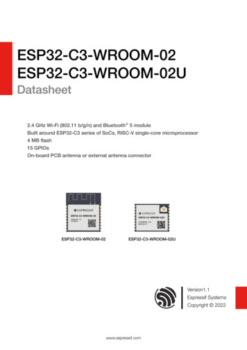
4. Electrical Characteristics# Notes:① Modem-sleep is used when such applications as PWM or I2S require the CPU to be working. In caseswhere Wi-Fi connectivity is maintained and data transmission is not required, the Wi-Fi Modem circuit canbe shut down to save power, according to 802.11 standards (such as U-APSD). For example, in DTIM3,when ESP8266EX sleeps for 300 ms and wakes up for 3 ms to receive Beacon packages from AP, theoverall average current consumption is about 15 mA.② Light-sleep is used for applications whose CPU may be suspended, such as Wi-Fi switch. In caseswhere Wi-Fi connectivity is maintained and data transmission is not required, the Wi-Fi Modem circuit andCPU can be shut down to save power, according to 802.11 standards (such as U-APSD). For example, inDTIM3, when ESP8266EX sleeps for 300 ms and wakes up for 3 ms to receive Beacon packages fromAP, the overall average current consumption is about 0.9 mA.③ Deep-sleep is for applications that do not require Wi-Fi connectivity but only transmit data over long timelags, e.g., a temperature sensor that measures temperature every 100s. For example, when ESP8266EXsleeps for 300 s then wakes up to connect to AP (taking about 0.3 1 s), the overall average currentconsumption is far less than 1 mA. The current consumption of 20 μA was obtained at the voltage of 2.5V.Temperature ( )4.4. Reflow ProfilePeak Temp.235 250 250Preheating zone150 200 60 120s217200Reflow zone217 60 90sCooling zone-1 -5 /sSoldering time 30sRamp-up zone1 3 /s1005025Time (sec.)00#50100150200250Ramp-up zone — Temp.: 150 Time: 60 90s Ramp-up rate: 1 3 /sPreheating zone — Temp.: 150 200 Time: 60 120s Ramp-up rate: 0.3 0.8 /sReflow zone — Temp.: 217 60 90s; Peak Temp.: 235 250 ( 245 recommended) Time: 30 70sCooling zone — Peak Temp. 180 Ramp-down rate: -1 -5 /sSolder — Sn&Ag&Cu Lead-free solder (SAC305)Figure 4-1. ESP-WROOM-S2 Reflow Profile Note:Solder the module in a single reflow. If the PCBA requires multiple reflows, place the module on the PCBduring the final reflow.EspressifNot Recommended For New Designs (NRND)#11/182022.03Submit Documentation Feedback
Not Recommended For New Designs (NRND)#12/182022.03Submit Documentation FeedbackABC12C4C3GNDADC INCHIP PUGPIO16MTMSMTDIMTCKMTDOThe values of C7, C6 and L1vary with the actual PCB PCB D3P3VDD RTCTOUTCHIP ENXPD DCDCU2GNDR1The values of C1 and C2 vary withthe selection of the crystal.33TBDC1GNDGNDU13ESP8266EXGPIO5SD DATA 1SD DATA 0SD CLKSD CMDSD DATA 3SD DATA 2VDDPSTGND26MHz( 10ppm)3231302928272625EXT RSTBRES12K NCVDDAVDDDXTAL IN NCXTAL OUT ND4GNDXIN1GND IO0CMD/MOSISD3/CSSD2/GPIO9GPIO4GPIO0GNDFigure 5-1. ESP-WROOM-S2 SchematicsPage Name ESP-WROOM-S2 15RXDPin.16TXDPin.17IO51RevConfidential and 8RSTPin.19ADC INADC INRSTPin.20ENCHIP PUGPIO16VDD33GNDPCB 8VCCEspressifGND#4D5ABCD5. Schematics#
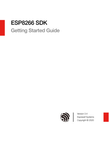
54326. Peripheral Schematics#6.Peripheral SchematicsVDD33VDD33C1 10uFC2 0.1uFGNDBOOT RXDC3GND321J2GNDSD1/INTGND10K10K10KTBDUART DOWNLOADSD0/MISOR13R14VDD3310K10KSD D2SD D3CMDCLKSD D0SD R12GNDGNDEN3V3ADC INIO16RSTIO15IO5IO2TXDIO0RXDIO4SD1/INTSD2/IO9 5678910J1GNDU2#HOSTFigure 6-1. ESP-WROOM-S2 Peripheral Schematics Note:Espressif SystemsTitle1. Soldering Pad 21 to the Ground of the base board is not necessary for a satisfactory thermalApplication of ESP-WROperformance. If users do want to solder it, they need to ensure that the correct quantity of soldering pasteSizeDocument Numberis applied.A4 Doc 5Date:2. To ensure the power 4supply to the ESP8266EX chip during the3 power-up, it is advised to add an RC delay2circuit at the EN pin. The recommended setting for the RC delay circuit is usually R 10 kΩ and C 0.1uF. However, specific parameters should be adjusted based on the power-up timing of the module andthe power-up and reset timing of the ESP8266 chip. For ESP8266EX’s Power-up and Reset TimingDiagram, please refer to Electrical Characteristics in ESP8266EX Datasheet.Wednesday, August3. To improve module’s anti-inference capability, it is advised to reserve an RC delay circuit at the RST pin.The recommended setting for the RC delay circuit is usually R 10 kΩ and C 0.1 uF.EspressifNot Recommended For New Designs (NRND)#13/# 182022.03Submit Documentation Feedback
7. Dimensions#7.Dimensions#Figure 7-1. Dimensions of ESP-WROOM-S2EspressifNot Recommended For New Designs (NRND)#14/# 182022.03Submit Documentation Feedback
7. Dimensions#8.Recommended PCB LandPattern#Figure 8-1. Recommended PCB Land Pattern of ESP-WROOM-S2EspressifNot Recommended For New Designs (NRND)#15/# 182022.03Submit Documentation Feedback
Appendix A#A.Appendix - LearningResourcesA.1. Must-Read Documents ESP8266 Quick Start GuideDescription: This document is a quick user guide to getting started with ESP8266. Itincludes an introduction to the ESP-LAUNCHER, how to download firmware on to theboard and run it, how to compile the AT application, structure and the debuggingmethod of RTOS SDK. Basic documentation and other related resources for theESP8266 are also provided. ESP8266 SDK Getting Started GuideDescription: This document takes ESP-LAUNCHER and ESP-WROOM-02 as examplesto introduce how to use ESP8266 SDK. The contents include preparations beforecompilation, SDK compilation and firmware download. ESP-WROOM-02 PCB Design and Module Placement GuideDescription: The ESP-WROOM-02 module is designed to be soldered to a host PCB.This document compares six different placements of the antenna on a host board andprovides notes on designing PCB. ESP8266 Hardware ResourcesDescription: This zip package includes manufacturing specifications of the ESP8266board and the modules, manufacturing BOM and schematics. ESP8266 AT Command ExamplesDescription: This document introduces some specific examples of using Espressif ATcommands, including single connection as a TCP Client, UDP transmission andtransparent transmission, and multiple connection as a TCP server. ESP8266 AT Instruction SetDescription: This document provides lists of AT commands based onESP8266 NONOS SDK, including user-defined AT commands, basic AT commands,Wi-Fi AT commands and TCP/IP-related AT commands. It also introduces thedownloading of AT firmware into flash. TCP/UDP UART Passthrough Test DemonstrationDescription: This guide is intended to help users run a TCP & UDP passthrough test onthe ESP8266 IoT platform. FAQEspressifNot Recommended For New Designs (NRND)#16/# 182022.03Submit Documentation Feedback
Appendix A#A.2. Must-Have Resources ESP8266 SDKsDescription: This website page provides links to the latest version of ESP8266 SDK andthe older ones. ESP8266 ToolsDescription: This website page provides links to the ESP8266 flash download tools andESP8266 performance evaluation tools. ESP8266 App ESP8266 Certification and Test Guide ESP8266 BBS ESP8266 ResourcesEspressifNot Recommended For New Designs (NRND)#17/# 182022.03Submit Documentation Feedback
Disclaimer and Copyright NoticeInformation in this document, including URL references, is subject to change withoutnotice.THIS DOCUMENT IS PROVIDED AS IS WITH NO WARRANTIES WHATSOEVER,INCLUDING ANY WARRANTY OF MERCHANTABILITY, NON-INFRINGEMENT, FITNESSFOR ANY PARTICULAR PURPOSE, OR ANY WARRANTY OTHERWISE ARISING OUTOF ANY PROPOSAL, SPECIFICATION OR SAMPLE.All liability, including liability for infringement of any proprietary rights, relating to use ofinformation in this document is disclaimed. No licenses express or implied, by estoppel orotherwise, to any intellectual property rights are granted herein.The Wi-Fi Alliance Member logo is a trademark of the Wi-Fi Alliance. The Bluetooth logo isa registered trademark of Bluetooth SIG.Espressif IoT TeamAll trade names, trademarks and registered trademarks mentioned in this document areproperty of their respective owners, and are hereby acknowledged.www.espressif.comCopyright 2022 Espressif Inc. All rights reserved.Not Recommended For New Designs (NRND)
Mouser ElectronicsAuthorized DistributorClick to View Pricing, Inventory, Delivery & Lifecycle Information:Espressif:ESP-WROOM-S2
Changed the minimum working voltage from 3.0V to 2.5V; Changed the power consumption during Deep-sleep from 10 μA to 20 A. 2017.02 V1.4 Updated Section 3.3. 2017.09 V1.5 Added Documentation Change Notification and the official link for downloading Product Certifications; Updated the supply voltage to 2.7V 3.6V;